


REV0 10.02.15
-H8-47-
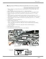
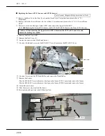
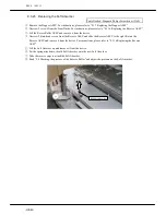
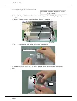
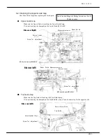
8.3.33 Replacing the DC Motor
Tools Needed: Magnetic Philips Screwdriver (No.2)
①
Read “8.3.9 Imprinting Head ASSY”
①~⑥
and remove the Imprinting Head ASSY.
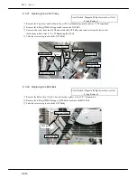
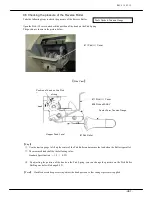
②
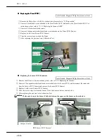
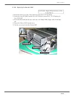
Unscrew 2 bind-head screws from the Ribbon Holder
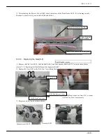
③
Unscrew 2 bind-head screws from the DC Motor and remove the DC Motor
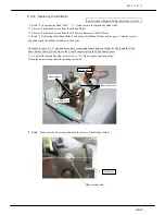
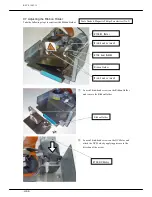
④
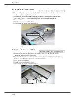
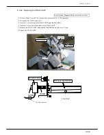
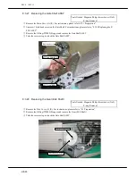
Read “9.7 Adjusting the Ribbon Holder” and adjust the Ribbon Holder, and the gears. Take the reverse
steps and attach the Ribbon Holder onto the device.
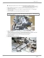
Check cable route “8.3.4” and make sure there is enough distance between the Motor Cable and the Ultra
Sonic Sensor Cable. Noise between the 2 could cause errors in the Ultra Sonic Sensor
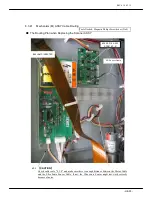
⑤
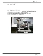
To adjust the Imprinting Gap, please refer to “ 9.5 Adjusting the Imprinting Gap”
⑥
Run the print test and check the printing condition.
Bind-head screw
#108 DC Motor
Ribbon Holder
Bind-head screw
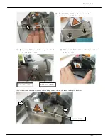
【
Note
】
Make sure the Gear is positioned in the center of the Ribbon Holder.
#106 Gear
Ribbon Holder Hole
Summary of Contents for HT-4139-28
Page 1: ...HT 4139 28 48 Scanner Maintenance Manual ...
Page 2: ......
Page 11: ... H2 5 2 5 Block Diagram ...
Page 22: ...REV0 10 02 15 H3 10 Lens Mirror Motor Mirror No 1 Mirror No 3 Mirror No 2 ...
Page 35: ...REV0 10 02 15 H7 2 ...
Page 63: ...REV0 2010 02 15 H7 30 ...
Page 89: ...REV0 10 02 15 H8 26 ...


