


REV0 10.02.15
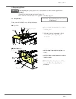
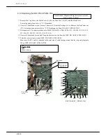
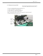
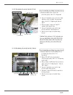
8.2.4 Replacing the Fluorescent Lamp (Back Side)
CAUTION
:
Wear gloves during this procedure;
z
To prevent injury from broken Fluorescent Lamp
z
To prevent the Fluorescent Lamp from being dirty
①
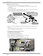
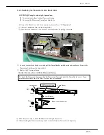
Remove the Main Cover (L). For instructions, please refer to “8.1 Preparation”
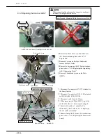
②
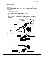
Unscrew 1 bind-head screw on the Lamp ASSY.
③
Disconnect the connector J73 and remove the Lamp ASSY by pulling it forward.
Bind-head screw
Connector J83
#4 Fluorescent lamp
#39 Lamp ASSY
(Back)
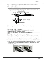
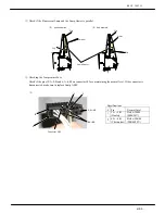
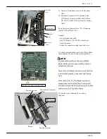
④
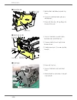
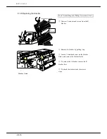
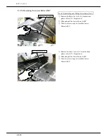
Loosen 2 washer faced heads screw and pull the Lamp Bracket in the direction shown below. Remove the
Fluorescent Lamp from the lamp socket.
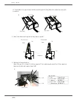
⑤
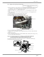
Replace the Fluorescent Lamp
Caution: Do not use force to lift the Fluorescent Lamp.
To attach the Fluorescent Lamp, push in the Fluorescent Lamp and place the Lamp Heater over it. If you
apply pressure on the tip of the lamp, the lamp may get damaged.
Washe faced head screw
Lamp Bracket
Remove
Mount
Insert
Pull
Lamp Heater
#4 Fluorescent lamp
Lamp socket
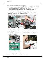
⑥
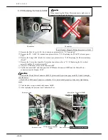
Take the reverse step to attach the Fluorescent Lamp to the device.
⑦
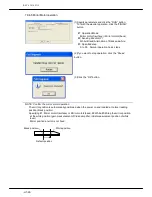
After attaching the Fluorescent Lamp, run the Auto Calibration Test (refer to Chapter 6)
-H8-7-
Summary of Contents for HT-4139-28
Page 1: ...HT 4139 28 48 Scanner Maintenance Manual ...
Page 2: ......
Page 11: ... H2 5 2 5 Block Diagram ...
Page 22: ...REV0 10 02 15 H3 10 Lens Mirror Motor Mirror No 1 Mirror No 3 Mirror No 2 ...
Page 35: ...REV0 10 02 15 H7 2 ...
Page 63: ...REV0 2010 02 15 H7 30 ...
Page 89: ...REV0 10 02 15 H8 26 ...


