


REV0 10.02.15
-H8-52-
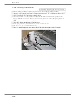
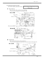
④
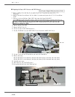
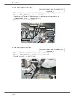
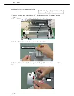
Take the reverse step for assembly
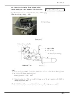
8.3.40
Replacing the F/L Sensor
Caution: Make sure to attach the Sensor properly.
It may be the cause of errors
Tools Needed: Magnetic Philips Screwdriver (No.2)
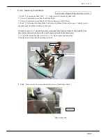
①
Remove the Pick Unit ASSY and the Pick (U)
Cover.
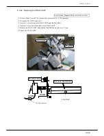
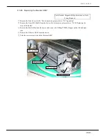
②
Unscrew 2 bind-head screws on the F/L Bracket
ASSY and remove the F/L Bracket
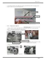
※
Do not pull hard to remove the F/L Bracket
ASSY. The F/L Sensor Cable is routed onto the
F/L Bracket ASSY.
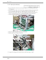
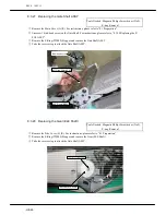
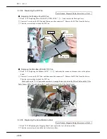
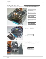
③
Disconnect the connector from the F/L Sensor
Cable.
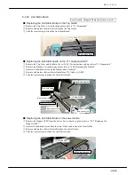
④
Unscrew 1 screw from the countersunk (FL) and
remove the F/L Sensor.
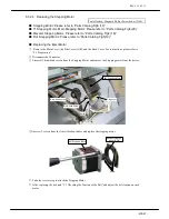
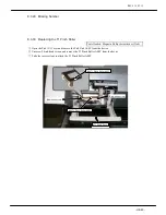
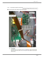
⑤
Take the reverse steps to attach the F/L Sensor
Plate(FL)
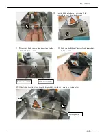
Pick(U)Cover
Bind-head screw
F/L Sensor
F/L Sensor Cable
F/L Sensor Connector
F/L Sensor Hook
Screw
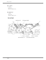
#58 F/L Sensor
(Photo Micro
Sensor ASSY)
#105 F/L Bracket ASSY
#58 F/L Sensor
F/L Sensor Cable
#105 F/L Bracket ASSY
#105 F/L Bracket ASSY
F/L Sensoe Hook
Summary of Contents for HT-4139-28
Page 1: ...HT 4139 28 48 Scanner Maintenance Manual ...
Page 2: ......
Page 11: ... H2 5 2 5 Block Diagram ...
Page 22: ...REV0 10 02 15 H3 10 Lens Mirror Motor Mirror No 1 Mirror No 3 Mirror No 2 ...
Page 35: ...REV0 10 02 15 H7 2 ...
Page 63: ...REV0 2010 02 15 H7 30 ...
Page 89: ...REV0 10 02 15 H8 26 ...


