


REV0 10.02.15
-H9-8-
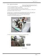
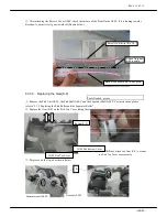
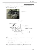
9.7 Adjusting the Ribbon Holder
Take the following steps to construct the Ribbon Holder.
①
Loosen 2 bind-head screws on the Ribbon Holder
and remove the Ribbon Holder
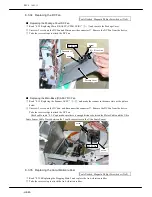
②
Loosen 2 bind-head screws on the DC Motor and
attach the DC Motor by applying pressure in the
direction of the arrow.
#108 DC Motor
Bind-head screw x2
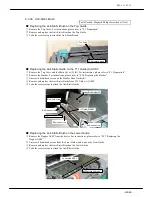
Ribbon Holder
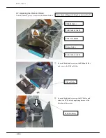
#108
DC Motor
Bind-head screw x2
#106
Gear
(NMB)
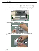
Ribbon Holder
Tools Needed: Magnetic Philips Screwdriver (No.2)
Summary of Contents for HT-4139-28
Page 1: ...HT 4139 28 48 Scanner Maintenance Manual ...
Page 2: ......
Page 11: ... H2 5 2 5 Block Diagram ...
Page 22: ...REV0 10 02 15 H3 10 Lens Mirror Motor Mirror No 1 Mirror No 3 Mirror No 2 ...
Page 35: ...REV0 10 02 15 H7 2 ...
Page 63: ...REV0 2010 02 15 H7 30 ...
Page 89: ...REV0 10 02 15 H8 26 ...


