


REV0 10.02.15
-H4-2-
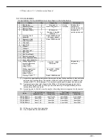
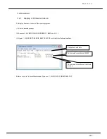
4.1 Diagnostic Item for each Operation
Refer to the section 4.2 to take a corrective action based on the information described in the table below.
I t e m ( A )
I t e m ( B )
C o n t e n t
R e f e r e n c e ( S e c . 4 . 2 )
Paper Feeding
•
Photo systems
PC
**
system error
*
(B)
Mechanism
•
DBL
Dual feed Detection error by the
PC22
(A)
•
Ultra Sonic Sensor
Systems
Detection error
(C)(V)
Paper Scanning
•
Paper error
Scanned image error
(D)(E)
Mechanism
•
Low quality image
Quality of whole or part image is
low
•
Light intensity error
Error after scanning
•
Lamp alarm
Lack of light intensity
(
Replace within 1 week
)
•
Lamp error
Light intensity error
(
Replace
ASAP
)
Parts
•
Photo systems
Maintenance M. 6.6.1
(G)(H)(J)
Replacement
•
Fluorescent lamp
Maintenance M. 8.2.3
(J)
•
Inverter
(
Lighting tool
)
Maintenance M. 8.3.11
(K)
(Front)
•
Scanner ASSY
Maintenance M. 8.3.5
(L)
•
Fluorescent lamp
Maintenance M. 8.2.4
(J)
•
Inverter
(
Lighting tool
)
Maintenance M. 8.3.12
(K)
(Back)
•
Scanner ASSY ASSY
Maintenance M. 8.3.10
(L)
•
P/K
Maintenance M. 8.3
MAIN
(
CPS619 P/K
)
Maintenance M. 8.3.2
(M)(N)
DRV
(
CPS614 P/K
)
Maintenance M. 8.3.3
(O)
SS
(
CPS618 P/K
)
Maintenance M. 8.3.4
(W)
•
Pick roller
(P)
•
Separator Roller
(Q)
•
Reverse Roller
Replaced by end user or service
personnel following the
Instruction manual
(R)
•
Imprinting ASSY
Maintenance M.8.3.9
(S)
•
Power Supply
(
PS ASSY
)
Maintenance M.8.3.1
(T)
•
Control Panel
Maintenance M.8.3.20
Imprinting
•
Improper print position
(F)
Print Head
•
Not clear
•
Print error
Maintenance
Maintenance M.3
At the maintenance
Summary of Contents for HT-4139-28
Page 1: ...HT 4139 28 48 Scanner Maintenance Manual ...
Page 2: ......
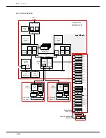
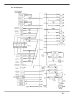
Page 11: ... H2 5 2 5 Block Diagram ...
Page 22: ...REV0 10 02 15 H3 10 Lens Mirror Motor Mirror No 1 Mirror No 3 Mirror No 2 ...
Page 35: ...REV0 10 02 15 H7 2 ...
Page 63: ...REV0 2010 02 15 H7 30 ...
Page 89: ...REV0 10 02 15 H8 26 ...


