17
_____________________________________________________________________________________________
4.1 Preparing for Real-time Data Acquisition
______________________________________________________________________________________________
4.1.4 Settings of Measurement Channels and Modules
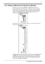
Double-click the icon of the MEMORY HiLOGGER registered for a
measurement system or click the plus (+) mark of the icon. The analog,
pulse, trigger, logic, alarm, and printer icons will then appear under the
logger icon. (Note that the logic, alarm and printer icons will not appear
unless the 8992 PRINTER UNIT and 8993 DIGITAL I/O UNIT are
connected to the MEMORY HiLOGGER.)
Double-click an icon (e.g., analog or pulse icon) or click the plus mark to
display the channel icons.
Click the channel, trigger, logic, alarm, or printer icon to display the related
"
Settings
" page. The setting items are similar to those for the MEMORY
HiLOGGER. For details, refer to the MEMORY HiLOGGER instruction
manual. The following settings, however, are not included or differ from
those for the MEMORY HiLOGGER.


