Appendix B. DIP Switch
B.1 DIP Switch Description
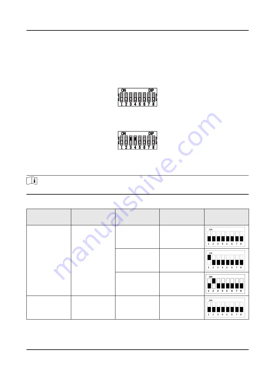
The DIP switch is on the main lane control board. No.1 to No 8 is from the low bit to the high bit.
When the switch is towards ON, it means the switch is enabled, otherwise, the switch is off. If you
set the DIP switch like the figure displayed below, its binary value is 00001100, and its decimal
value is 12.
B.2 DIP Switch Corresponded Functions
Note
After setting the DIP switch, you should reboot the device, or the function cannot take effect.
The 8-bit DIP switch corresponded functions on the access control board are as follows:
Bit
Device Mode
Function
Decimal Value
DIP Switch
Address Diagram
1 to 2
Work Mode
Normal Mode
0
Study Mode
1
Test Mode
2
3
Memory Mode
Enable Memory
Mode
0
DS-K3B601SX Series Swing Barrier User Manual
103
Summary of Contents for DS-K3B601S Series
Page 1: ...DS K3B601SX Series Swing Barrier User Manual ...
Page 36: ...Figure 4 8 Interface and Corresponded UART No DS K3B601SX Series Swing Barrier User Manual 22 ...
Page 38: ...DS K3B601SX Series Swing Barrier User Manual 24 ...
Page 40: ...Entering Wiring Exiting Wiring DS K3B601SX Series Swing Barrier User Manual 26 ...
Page 124: ...UD23132B D ...


