


5.7 Start-up
36
BUS-C
O N N E C T I O N
Depending on the available interface option of the device, the CAN bus of the device is either con-
nected directly, via a nine-pin Sub-D connector (-A28), or alternatively via a protocol converter (-A29)
for the connection to the automation systems of the test bench. The cables and plug used depend
on the installed interface (see
section 7.3, p. 68
). Before connecting the CAN bus, the terminating
resistor must be removed.
Take care to secure the plug against unwanted loosening. Use the fastening screws or the snap-in
mechanism for this purpose.
S
E CU RI T Y
C
O N T A C T S
Safety-relevant signals such as the E-stop can be controlled with potential-free contacts or transmit
the status of the device with potential-free contacts. The contacts can be found on the terminal
-X4.1, -X4.2 and -X4.3 in the HTS cabinet and can be connected by single or multi-core cables. If some
of the control contacts are not used, they must be bridged to enable operation.
A description of the pin assignment of the contacts can be found in
section 7.1, p. 66
.
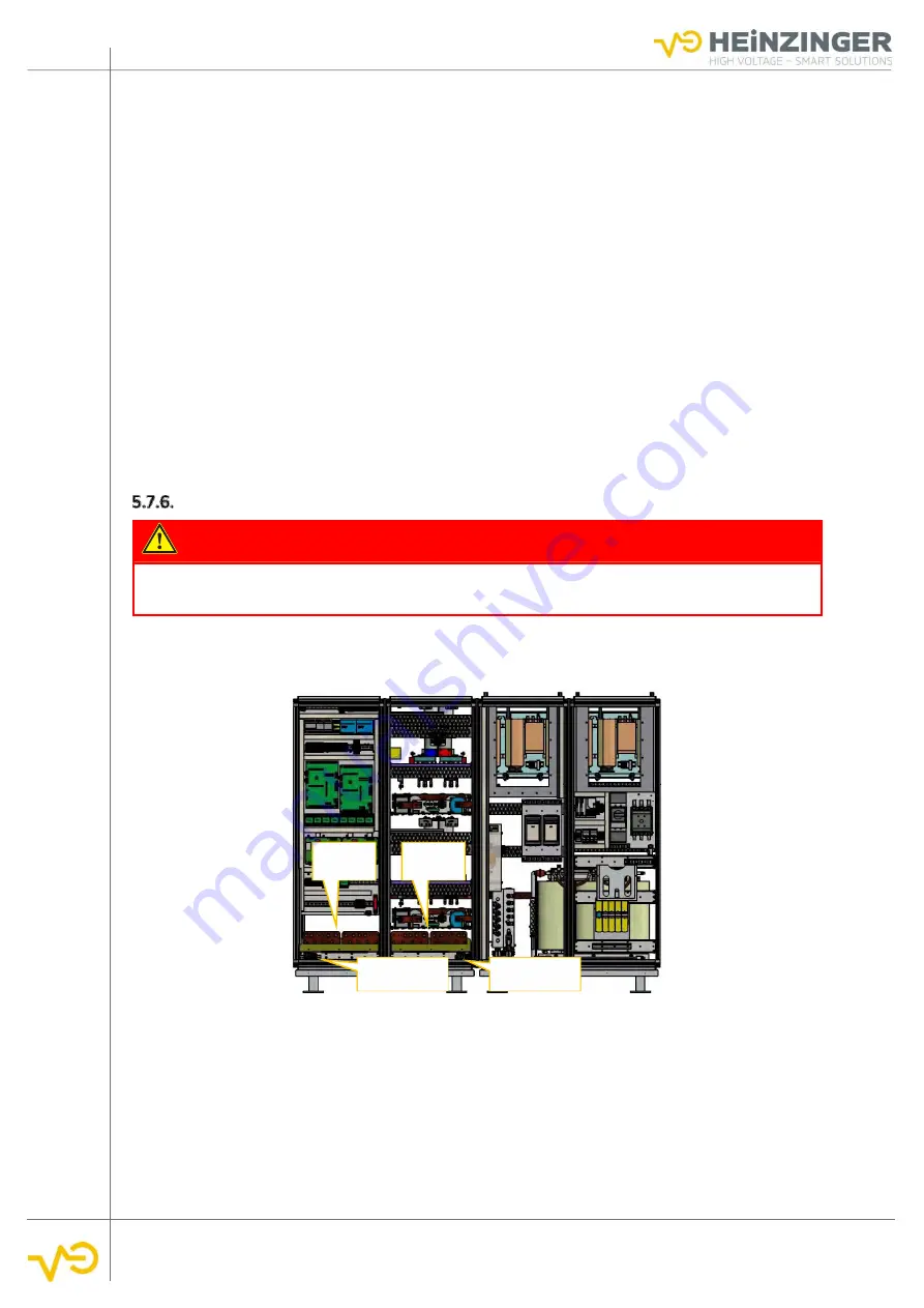
Load- and Sense-Connection
DANGER
Even after switching off, dangerous voltages can still be present on the output rails. If neces-
sary, a discharge of the residual charges must be provided!!
The DC output of the ERS system is potential-free and is monitored against earth fault by an isolation
monitor. The output channels are always equipped with contactors which safely disconnect the ERS
system from the test object in the event of a fault or when the unit is switched of.
Output
Channel 1
Sense
Channel 1
Sense
Channel 2
Output
Channel 2
Fig. 31 Output channels and sense terminal, 2 channel system