heinzinger ERS-BIC User Manual Download Page 101

Manual ERS-BIC 160 kW V2.1 


99 

B . F .


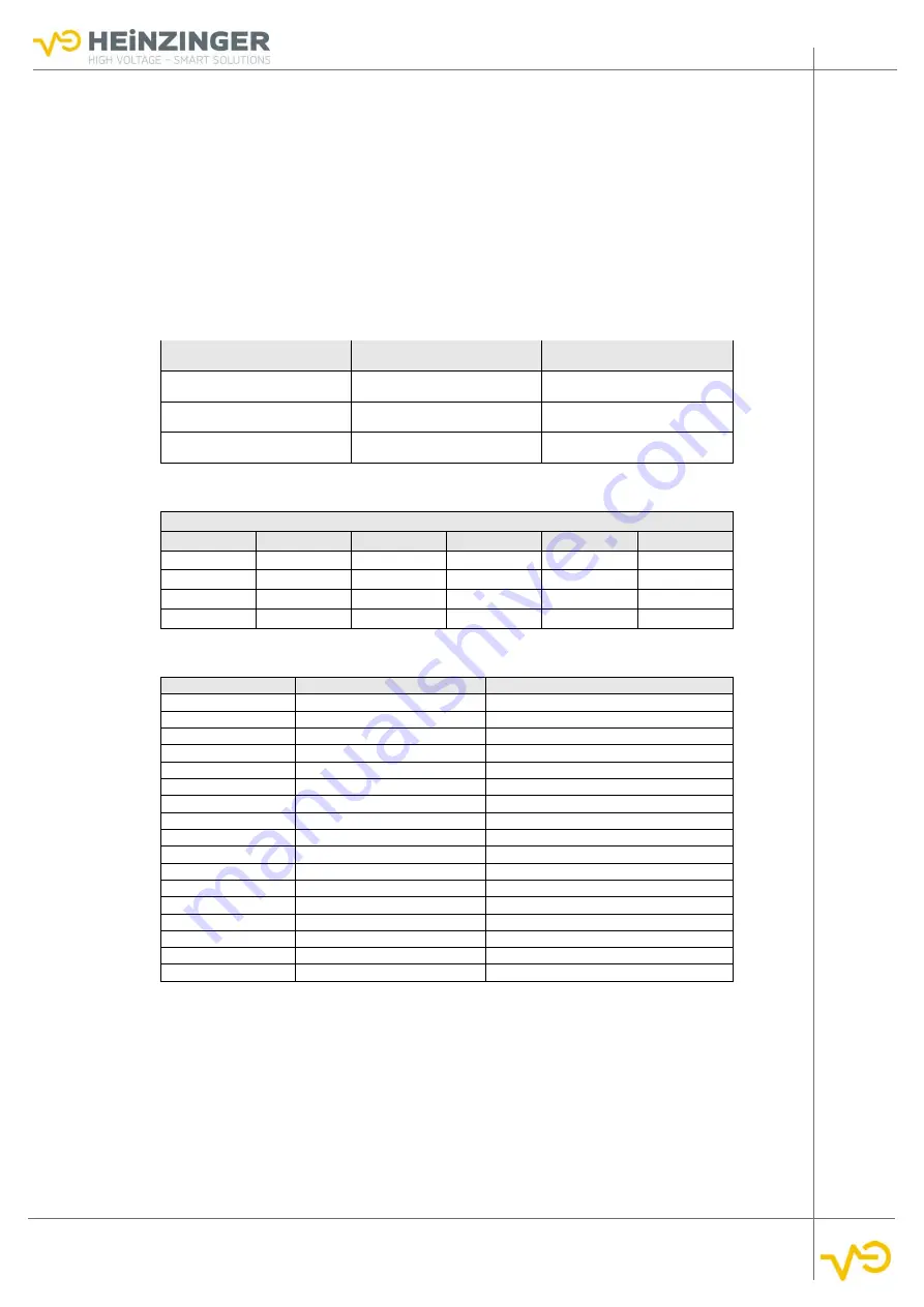
  Co nt r o l l e r   m o d e   “ B a t t e r y   T e s t ”    


Optimized for voltage-controlled bidirectional operation on inverters, DCDC converters, etc. 


Controller is optimized for disturbance variables, i.e. designed for load jumps 

E

X A M P L E  

B

A T T E R Y 

T

E S T

:


Test item:  


Battery with 400V 


Control mode:  

voltage control CV 


Operating mode:  

bidirectional 

Correct


Wrong


Wrong


V

set

 = 400 V 

V

set

 = 440 V 

V

set

 = 

380


V


I

set

 = 100 A 

I

set

 = 100 A 

I

set

 = 100 A 

P

set

 = 50 kW 

P

set

 = 

0 kW


P

set

 = 50 kW 

C.


E L ECTR OC H E MIC A L P O TE NTI A L S  

Potentials against hydrogen of selected materials 
Material 

Potential/V 

Material 

Potential/V 

Material 

Potential/V 

Aluminum 

-1.67 

Mangan 

-1.05 

Zinc 

-0.76 

Chrome 

-0.71 

Iron(II) 

-0.44 

Cobalt


-0.28


Nickel 

-0.25 

Tin 

-0.14 

Lead 

-0.13 

Iron(III) 

-0.037 

Hydrogen 

Copper 

0.34 

D .


RE FE RE N CE   L I S T   A C CE S S O RI E S  

Accessory-Nr. 

Heinzinger-Item Number 

Designation 

05.070.308.20 

Cage clamp 22-28 VA 

4a 

05.070.308.39 

Cage clamp 22-28 

4b 

05.070.308.38 

Counter trough 22-28 

5a 

05.070.308.40 

Cage clamp 16-22 

5b 

05.070.308.41 

Counter trough 16-22 

6a 

05.070.308.42 

Cage clamp 12-16 

6b 

05.070.308.43 

Counter trough 12-16 

7a 

05.070.308.44 

Cage clamp 34-40 

7b 

05.070.308.45 

Counter trough 34-40 

20 

06.020.672.02 

Cover profile 

21 

06.030.348.60 

Rail for serial connection 

22 

06.030.354.14 

PE-CU-rail 

23 

06.030.502.00 

Hose clamps 

30a 

06.030.118.50 

Bolt M10x40 

30b 

06.030.122.00 

Washer  

30c 

06.030.124.26 

Spring washer 

30d 

06.030.125.10 

Nut M10 

Summary of Contents for ERS-BIC

Page 1: ...Betriebsanleitung User Manual Bidirectional Power Supply System Heinzinger ERS BIC www heinzinger com...

Page 2: ...reich Stromaufnahme supply voltage frequency range current consumption Output Ausgangsspannung Ausgangsstrom Ausgangsleistung output voltage output current output power Options M Modifikation M Modifi...

Page 3: ...and Operating Guide 8 Intended Use 8 Residual Risks and Precautions 8 3 Technical Specification 9 Table 1 Dimension Weight 9 Table 2 Mains Connection 9 Table 3 Output 9 Table 4 Display Control 9 Tabl...

Page 4: ...ibility 24 Assembly Instruction 25 Mechanical Assembly 25 Installation of the Cooling System 27 Filling and Venting the Cooling Circuit 29 Electrical Assembly of the ERS 30 Connecting Power Circuits 3...

Page 5: ...60 Service Parameters 61 Battery Models optional 61 Model 1 61 Model 2 61 Model 3 61 Model 4 61 Cluster Operation optional 61 Description 61 Parallel Cluster Operation 62 Serial Cluster Operation 63...

Page 6: ...71 Error Messages 73 Troubleshooting Cluster Operation 78 9 Care Maintenance Calibration 79 Care and Cleaning 79 Venting the Cooling Circuit 79 Service and Maintenance 79 Not Using the Device 79 Calib...

Page 7: ...ease see the terms of the agreement Unauthorized conversions and modifications to the system as well as the use of non approved spare parts will void all liability and warranty on the part of the manu...

Page 8: ...which personal injury may occur N O T I C E Draws your attention to information that must be observed in particular to prevent impairment and damage to and by the device Significance of the Manual Pl...

Page 9: ...at least 5 minutes after switching off the ERS before opening the cabinet doors Requirements to Personnel The device is designed for commercial use The personnel are therefore subject to the statutor...

Page 10: ...ly component testing in test bench applications Extensions conversions or repairs may only be carried out by persons authorized by the manufacturer The electrical installations comply with the applica...

Page 11: ...0 A Mains connection phase 1 x eyelet bolt 10 mm Table 3 Output Output Voltage Vnom 600 V 1200 V Output current Inom 600 A 1200 A Discharge time no load 1 minute Efficiency 93 Output polarity floating...

Page 12: ...change in set value 1 ms resistive load Control time at step in load 10 to 90 1 ms resistive load Stability over an 8 hour period constant conditions 0 1 UNOM Residual ripple 0 2 UNOM for f 0 1 MHz Ta...

Page 13: ...tioning of coolant connection See section 5 3 3 p 23 Table 9 Battery Models Range internal resistance 0 1 1 resolution 0 1 m Battery model optional 3 standard battery models as RC network integrated T...

Page 14: ...4 1 Device Views 12 4 DESIGN AND FUNCTION Device Views Exterior view Output Channel 1 Output Channel 2 Mains switch Touch display Fig 1 Exterior view ERS BIC...

Page 15: ...Manual ERS BIC 160 kW V2 1 13 Inside view Mains connection 3p PE N Coolant connec tion Output Unit Channel 2 Output Unit Channel 1 Isolating transfor mer Controlboard HTS Fig 2 Interior view ERS BIC...

Page 16: ...ing source operation of the ERS it feeds the energy absorbed at the output of the ERS back into the grid via the transformer during sink operation HTS A Multi Parallel Converter MPC serves as a step u...

Page 17: ...ind an overview of the possible current combinations depending on the device type Table 12 Specifications single channel mode Device type 1200 1200 160 Voltage 2 channels 600 V Current 2 channels 600...

Page 18: ...depending on the device type Table 13 Specifications parallel mode Device type 1200 1200 160 Voltage 1 Channel 600 V Current 1 Channel 1200 A Power 1 Channel 160 kW Mains 3P 400 V 50 Hz control syste...

Page 19: ...ible current combinations depending on the device type Table 14 Specifications serial mode Device Type 1200 1200 160 Voltage 1 Channel 1200 V Current 1 Channel 600 A Power 1 Channel 160 kW Mains 3P 40...

Page 20: ...00 600 00 750 00 900 00 1050 00 1200 00 0 100 200 300 400 500 600 700 800 900 1000 1100 1200 CURRENT IN A VOLTAGE IN V single channel mode parallel serial Fig 10 Power hyperbola of two ERS BIC 1200 12...

Page 21: ...ormance Level D optional Safe separation Optional using a double set of redundant contactors at the output Signal lamps Optional Insulation monitoring of each channel optional Quick discharge of the i...

Page 22: ...ing of the response values is done via a setting menu using the device keys and a graphic LCD The selected settings are stored in a permanent memory After switching on the insulation monitor carries o...

Page 23: ...00 kg HTS cabinet 500 kg Unpacking the Unit WARNING Under no circumstances put the device into operation if it is visibly damaged The ERS is delivered in wooden boxes or with direct packaging with lig...

Page 24: ...cordance with the installation plan Fig 12 p 22 Ensure that the room is adequately venti lated so that the maximum permissible am bient temperature is not exceeded Clearances There must be sufficient...

Page 25: ...the cooling circuit should be selected so that they have a small voltage difference see appendix C p 99 with the aluminum heat sinks in the device so that there is no contact corrosion and or pitting...

Page 26: ...tion compliance with the specific safety regula tions and the handling of any radio interference are the responsibility of the owner The following rules for installation must be observed In order to p...

Page 27: ...y 600V 4A e g Heinzinger GEN 600 4 Insulation tester for example Grossen Metrawatt Secutest 8 pieces crocodile clips long 5 pieces measuring cable 0 5 m Service plug Heinzinger 2 x Sense cable connect...

Page 28: ...cabinet segments have been placed at the intended location they can be fixed and screwed together with the aid of the bayed connectors The bayed connectors are already preinstalled in the AFE cabinet...

Page 29: ...ts with a rated of 160kW the block is to the left side of the input trans former All internal connections must be restored before connecting to the building s cooling circuit Reconnect the internal co...

Page 30: ...nation It is strongly recommended to install a fine water filter in front of the ERS system so that no con taminants can get into the system The cooling water circuit is equipped with a G 1 screwed co...

Page 31: ...he solenoid valve the cooling water will flow through the ERS Afterwards check whether all connections at the water block are tight or whether leaks are present VENTING THE ERS COOLING SYSTEM Remove t...

Page 32: ...binet segments and the network or the automation system must be made INTERNALLY DC Intermediate circuits 24V supply and control lines CAN Bus Grounding Connecting Power Circuits Due to the separation...

Page 33: ...strain relieved on the rail below the fuses using the clamps from the accessory pack Reference No 4a 4b N O T I C E When connecting the cables to the DC bus make sure that the insulation plate of the...

Page 34: ...ts For this purpose sockets are installed in the upper side of the AFE cabinet which must be connected to the plugs coming from the other cabinets Table 18 Overview signal lines Cabinets Connection 1...

Page 35: ...re them against loosening Internal Grounding In order to ensure the sufficient grounding of all components installed in the cabinet grounding rails are installed on the rear side in the lower half of...

Page 36: ...t is possible to make the connection via a common PEN conduc tor For this purpose a bridge minimum cross section 6 mm must be placed between the N terminal and the PE terminals However this requires t...

Page 37: ...support rail on the cabinet floor from stress Make sure that the shield contacts a large area to ensure the best possible shielding WARNING Risk of electric shock After installation the covers must b...

Page 38: ...ential free contacts The contacts can be found on the terminal X4 1 X4 2 and X4 3 in the HTS cabinet and can be connected by single or multi core cables If some of the control contacts are not used th...

Page 39: ...OAD The load is connected to the DC output rails with correct polarity Output and Output using shielded cables with sufficient current carrying capacity and dielectric strength The connection is prepa...

Page 40: ...em has been electrically connected and connected to the mains the insulation test must now be carried out You need a commercially available insulation tester and must connect the PE connection of the...

Page 41: ...pply which can generate at least 2 5 kV and is equipped with a current limiter max 10 mA You will also need 8 crocodile clips 5 laboratory cables and a special service plug to connect the phases DANGE...

Page 42: ...ole of the high voltage power supply The short circuit must be created internally before the output relays The negative pole is connected to the device earth grounding rail 5 While observing the curre...

Page 43: ...cure against reconnection Verify that the system is dead Carry out grounding and short circuiting Provide protection from adjacent live parts DANGER Even after switching off the power supply residual...

Page 44: ...hannels DANGER High voltage Make sure that you do not touch the upper contacts of the fuse holders while the unit is switched on Connect at the outputs CH1 with CH2 and CH1 with CH2 using an appropria...

Page 45: ...as booted and make the following settings Deactivation of the undervoltage moni toring Set the minimum value of the DC link voltage to 20 V Now switch on the auxiliary power supply and set the voltage...

Page 46: ...V in the IBN interface Now parameterize the channels according to step 8 of the set point table and check the function of the system once again but now with active AFE Table 20 Set values external sup...

Page 47: ...structions for Operation WARNING Commissioning and operation only by trained specialist personnel Switching the Unit On and Off When switching the device on and off the following sequences should be o...

Page 48: ...ration Batt Sim Batt Test Always set all set values for V I and P I and P have to be nega tive when the system has to take in energy even when Dis charge or Sink has been chosen as mode of operation T...

Page 49: ...Control of wiring mode single parallel serial cluster for channel stop Signal lights optional Five color signal light on the roof of the system Section 4 5 1 p 19 CAN Bus Remote control Automation Sec...

Page 50: ...e 2 Channel 1 displayed Choose Channel 1 for display 3 Channel 2 displayed Choose Channel2 for display 4 Actual Values Current voltage power 5 Set values Current voltage power Input of set values Curr...

Page 51: ...de CP 16 Pause battery test or bidirectional operation battery simulation active Choose pause battery test or bidirectional operation battery simulation 17 Charge battery test or source mode battery s...

Page 52: ...ses to device damage Use the Enter Password button to enter the passwords to enable access to the locked submenus The Reset Password button locks access to all setup menus By default the password leve...

Page 53: ...tware versions used Table 24 System Info Designation Function Device Info Display of device data such as article number output power number of outputs and serial number SW Versions Display of the curr...

Page 54: ...Relay Switching Cycles Counter for switching cycles of the output contactors On the basis of the switching cycles the wear of the relay contacts can be determined When a predefined threshold is reach...

Page 55: ...vices there are two additional columns Table 26 Menu System Info Measurements Designation Function V INT Internal voltage V Sense Measured sense voltage V PRI DC link voltage primary circuit V SEK DC...

Page 56: ...ble 27 Menu System Info FPGA Diagnose Designation Function RS485 STATUS RX Status RS485 Interface RS422 STATUS A Status RS422 A RS422 STATUS B Status RS422 B HTS_ERR Error messages HTS Error Display o...

Page 57: ...ult the hexadecimal code can be passed on to the Heinzinger Service and is used for system diagnosis Table 28 Menu System Info DSP Diagnosis Designation Function CPUx Error Error number DSPx hexadecim...

Page 58: ...A list of possible error and warning codes can be found in section 8 5 pp 71 Table 29 Menu System Info Error History Designation Function Device Error code Hexadecimal and time stamp System time globa...

Page 59: ...ing mode is only possible in the de energized state Operating mode Switching between cluster and single device mode CAN BUS Interface Settings for the CAN BUS interface Cooling System Activate deactiv...

Page 60: ...is displayed Int Voltage monitoring Switch off threshold and delay time for internal volt age monitoring Output voltage monitoring Switch off threshold and delay time for monitoring the output curren...

Page 61: ...vation of the fast discharge function is necessary if there is a risk of overloading the discharge resistor due to external voltage sources ISO Monitoring Activate deactivate insulation monitoring CAN...

Page 62: ...he control loop Set Value Ramp Definition of the set value ramp via voltage time always same slope or input of a time for the ramp always same time ramp slope is calculated depending on the set value...

Page 63: ...eters for the simulated equivalent circuit The following setting ranges apply to the parameters the values for R2 and C are not used for battery model 4 R1 0 1 m 1 R2 0 1 m 1 C 0 1 F 100 F Four possib...

Page 64: ...individual channels of the ERS systems in parallel thus doubling the output power and quadrupling the current Below there is an overview on the possible device output for parallel cluster mode Table 3...

Page 65: ...ection of two devices that are in serial wiring mode is not allowed The following table shows the possible output depending on the device type Table 34 Specifications serial cluster operation Device t...

Page 66: ...l active If the ERS systems also have the option channel stop an additional communication line for the emergency stop relays must be established The control lines from the slave device to the automati...

Page 67: ...device now shows the normal main menu again Step 2 While the systems are switched on disconnect CAN A und RS422 No restart is necessary Step 3 End cluster operation The menu Unit Operation is unlocke...

Page 68: ...effective independent of all other switch positions and device settings also independent of the settings from the digital interface Normal device operation is only possible if the interlock function i...

Page 69: ...Contactor optional On X4 3 there are potential free contacts from Performance Level C on which output the status of the output contactors This allows a safe detection of the status at the output of th...

Page 70: ...pages The Firmware Download TP tool is also available there with which the updated firmware can be downloaded to the gateway Note Save a copy of the configuration before downloading the new firmware...

Page 71: ...this the pins 4 5 7 and 8 have to be connected with the housing ground Profibus uses a 9 pin Sub D Plug that is assigned according to Fig 63 A maximum current of 80 mA can be drawn from pins 5 and 6 f...

Page 72: ...it is disconnected from the grid by means of the mains contactor After eliminating the cause of the error the device must be switched on again Temperature Monitoring Temperature switches are installed...

Page 73: ...warnings is represented in a 16 bit data word The warnings can be divided into the following areas Warning code 0xn1mm n area of warning mm Code Warning areas Warnings of channel 1 0x1100 0x11F Contr...

Page 74: ...7 INIT_SERV_PARA_WARN forbidden service parameter at initialization 0x18 INIT_OPER_DATA_WARN forbidden operation mode parameter at initialization 0x19 LOCKED_OPTION option not released 0x1A CONTROL_PA...

Page 75: ...a of error Error of channel 1 0x1000 0x10FF Control Unit 1 Error of channel 2 0x2000 0x20FF Control Unit 2 Error of channel 1 0x6000 0x60FF Control Unit 2 Error of channel 2 0x7000 0x70FF Control Unit...

Page 76: ...ached secondary voltage 0x1E V_MON_SEC_UV_ERR Undervoltage limit reached secondary voltage 0x1F TEMP_CB_ERR Over temperature Control Unit 0x20 AFE_CHOP_ERR AFE Chopper timeout 0x21 OVP_SENS_ERR Overvo...

Page 77: ...mit reached 0x3A C_MON_HTS4_NEG_ERR Neg inductor current limit reached 0x3B OUT_REL_ERR_2 Error on output contactor 2 0x3C DISCHARGE_R_OT Overtemperature discharge resistor 0x3D ACC_OVFL Accumulator O...

Page 78: ...SW Error I2C Access Error No Access to I2C registry 0x54 CAN_BAUDRATE_ERR Internal SW Error Error at CAN baud rate settings 0x55 CAN_TRS_ERR Internal SW Error CAN Message cannot be transmitted last m...

Page 79: ...0x9A CLUSTER_OTH_UNIT Cluster configuration of other device 0x9B CURRENT_SENSE C_Out not equal to sum of C_HTSx 0x9C CURRENT_SYM_HTS1 Symmetry error current HTS1 0x9D CURRENT_SYM_HTS2 Symmetry error c...

Page 80: ...properly when switching over the device operation In this frozen state the system tries to read from an incorrect EEPROM address Solution To solve the problem switch between Master Slave Off After swi...

Page 81: ...to maintain the long term availability of the system and to safeguard your investment reg ular maintenance and equipment checks are recommended The intervals between the required maintenance works dep...

Page 82: ...no guarantee can be given for the safety and function of the device If necessary please contact our service department Service Address Maintenance and repair work is carried out directly by the manuf...

Page 83: ...alue Ranges 97 Control Schematics 96 Controller Settings 98 Control Parameters 60 Coolant 23 Coolant Connection 12 Coolant Monitoring 70 coolant temperature 23 Coolant Temperature 71 Cooling System 23...

Page 84: ...Ramp 58 Range of Use 8 Rapid Discharge 58 Residual Risks 8 S Safety Concept 19 Safety Instructions 7 Safety rules 7 Safety Symbols 8 Scope of Delivery 5 21 Sense Connection 69 Sense Monitoring 58 Ser...

Page 85: ...Remote 8 Variable 1 1 0x132 CH_2_MAX_SET_VAL DSP Remote 8 Variable 1 2 0x141 CH_1_BAT_MODEL_STATUS DSP Remote 8 1 0x142 CH_2_BAT_ MODEL_STATUS DSP Remote 8 2 0x151 CH_1_STATUS_II DSP Remote 8 Variabl...

Page 86: ...H_1_SET_PRE_CTRL Remote DSP 8 1 Remote 0x2A2 CH_1_SET_PRE_CTRL Remote DSP 8 2 Remote 0x2B1 CH_1_SET_SYM_CTRL Remote DSP 8 1 Remote 0x2B2 CH_1_SET_SYM_CTRL Remote DSP 8 2 Remote 0x2C1 CH_1_SET_PROT Rem...

Page 87: ...UERY Remote DSP 2 1 Remote 0x492 CH_2_GET_SEC_CTRL_QUERY Remote DSP 2 2 Remote 0x4A1 CH_1_GET_PRE_CTRL_QUERY Remote DSP 2 1 Remote 0x4A2 CH_2_GET_PRE_CTRL_QUERY Remote DSP 2 2 Remote 0x4B1 CH_1_GET_SY...

Page 88: ...isolation monitor Ch4 10 0 1 CLR_ERR_WARN_BUFFER Clears all error and warning memories 2 16 17 CHANNEL_WIRING 0 Normal normal wiring single channel 1 Parallel parallel wiring of the channels 2 Serial...

Page 89: ...e 1 Slave Channel 2 is Slave for cluster mode 4 5 32 47 0 65355 DEV_ERR_CODE Current Error code in the device 6 7 48 63 0 65355 DEV_WARN_CODE Current Warning code in the device A D Device Status II ID...

Page 90: ...er controlled 1 8 11 0 8 PAR_ID Choose parameter set 12 0 1 RESET_Q Reset Coulomb Counter 14 15 0 2 OPER_MODE Battery test mode 0 PAUSE 1 DISCHARGE 2 CHARGE Battery simulation 0 BIDI 1 SINK 2 SOURCE 2...

Page 91: ...TRL_MODE_ACT 1 CV Act voltage control active 2 CC Act current control active 4 CP Act power control active 14 15 0 2 OPER_MODE Mode of operation battery test mode 0 PAUSE 1 DISCHARGE 2 CHARGE Battery...

Page 92: ...are limited to the limits The valid set values are output periodically only in case of changes or only after request at the remote interface ID Name Message ID Data Length Sender Receiver Cycle Time C...

Page 93: ...e current 4 5 32 47 32768 3276 7 P_SET_MAX 325 kW 10 W 325 kW 100 W maximum set value power A L CHARGE DISCHARGE Registry ID Name Message ID Data Length Sender Receiver Cycle Time CHARGE_DISCH_QUERY 0...

Page 94: ...Name Message ID Data Length Sender Receiver DEV_QUERY_READ_ERROR 0x360 1 Byte Remote ERS Byte Bits Name Description 0 0 7 SELECTION 0 answer 1 timestamp in ms since last SW restart 1 answer 2 timesta...

Page 95: ...R_CODE channel error code 1 8 15 2 16 21 2 3 22 31 0 1023 0 999 TIMESTAMP 0 Timestamp in ms 4 7 32 63 0 FFFFFFFFh 0 4294967295 TIMESTAMP 1 Timestamp in s since 1970 01 01 A Q Device Warnings On this m...

Page 96: ...ferences the time since the start of the SW New time stamp references the time since 1970 01 01 in ms ID Name Message ID Length Sender Receiver CH_READ_WARN_QUERY 0x371 Channel 1 0x372 Channel 2 1 Byt...

Page 97: ...n DSP1 Index 0x001 SW Version DSP2 Index 0x002 SW Version FPGA Index 0x010 serial number Index 0x020 date of last calibration yyyymmdd Index 0x040 designation of the device ID Name Message ID Data Len...

Page 98: ...96 B DIGITAL CONTROL LOOP B A Control diagram...

Page 99: ...Control Setting Range Typical Value P ratio 0 0001 6500 0 1 6 5 I ratio 0 0001 6500 0 01 1 0 Ramp 0 1000 V ms y 0 1000 ms 0 1 1000 B C B Current Control Current Control Setting Range Typical Value P r...

Page 100: ...er Setting Effect of the Load The length of the supply lines influence the control Additional inductance 1m ca 1uH The capacity of the load affects the control behavior The location of the sense measu...

Page 101: ...tial V Aluminum 1 67 Mangan 1 05 Zinc 0 76 Chrome 0 71 Iron II 0 44 Cobalt 0 28 Nickel 0 25 Tin 0 14 Lead 0 13 Iron III 0 037 Hydrogen 0 Copper 0 34 D REFERENCE LIST ACCESSORIES Accessory Nr Heinzinge...

Page 102: ...100 E DECLARATION OF CONFORMITY...

Page 103: ...iche Genehmigung der Heinzinger electronic GmbH darf diese Be triebsanleitung oder Teile daraus weder vervielf ltigt reproduziert verteilt noch in eine an dere Sprache bersetzt werden DISCLAIMER The i...

Page 104: ...Heinzinger electronic GmbH High Voltage Smart Solutions Anton Jakob Strasse 4 83026 Rosenheim GERMANY Phone 49 8031 2458 0 Fax 49 8031 2458 58 info heinzinger de www heinzinger com V2 1 07 06 2021...

Reviews: