background image

GK600E User Manual


                                          Chapter 4 Operation and Run Instructions  


- 43 -   

  to get into  parameter edit status (get into passw ord  authentication status if  parameter 

under  passw ord  protection).  Directly  get  into  frequency  modification  status  w hen  receive 

UP/DOWN command from terminal, or 

  and 

  pressing on control panel. Sw itch to 

fault display status once a fault occurs or an alarm is given.   

4.1.3.2    Run Parameter Display  Status 

In case there is no fault, the drive w ill get into run parameters display status upon receipt of run 

command.  Default display is run frequency, and other parameters can be displayed through 

setting of L1-00 and L1-01 and press 

  to shift.  For example, in run status, w hen  users 

need to check bus voltage, motor speed, and input terminals status,  please set L1-00= 0084 

and  L1-01=  0004,    and  press 

  to  shift  to  the  display  of  bus voltage,  then  press 


again to display motor speed, and then press 

  to display input terminals state value.   


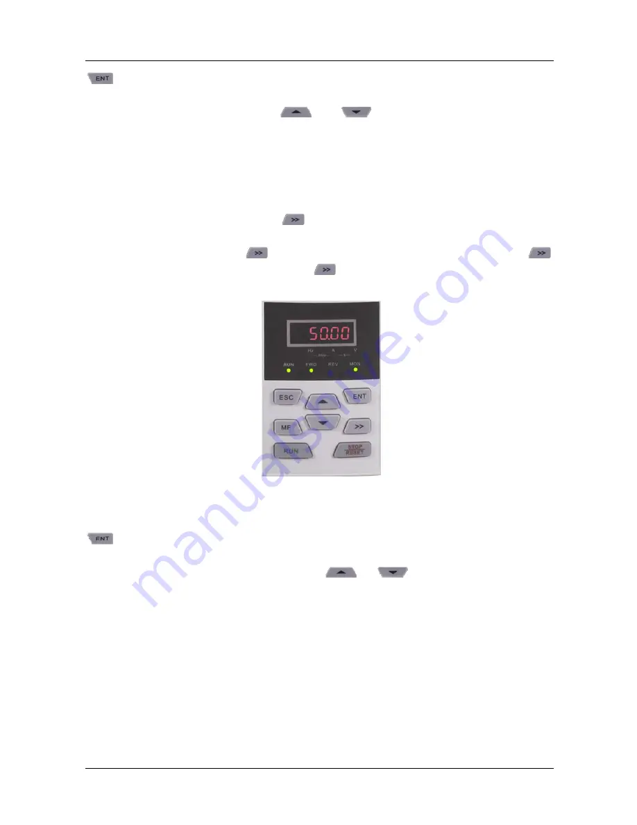
Fig. 4-3 Run parameter display status (Displaying run frequency 

– 50.00Hz) 

Stop status w ill be enabled immediately upon receipt of stop command in such a status. Press 

  to get into  parameter edit status (get into passw ord  authentication status if  parameter 

under  passw ord  protection).  Directly  get  into  frequency  modification  status  w hen  receiving 

UP/DOWN command from terminal, or pressing 

  or 

. Sw itch to fault alarm display 

status once a fault occurs or an alarm is given.    

4.1.3.3    Fault Alarm Display  Status 

In case a fault occurs or an alarm is given, the drive w ill get into fault or alarm display status. 


Summary of Contents for GK600E-4T11B

Page 1: ......

Page 2: ...tallation Operation must conform to the requirements of this manual and local industrial safety regulations and or electricalcodes Contents of this manual may be subject to appropriate modification as a result of product upgrade specification change and update of the manual In the event of damage or loss of user manual users may ask local distributors offices or our Technical Service Department fo...

Page 3: ...ures of GK600E 8 2 5 Parts Draw ing 11 2 6 Appearance Mounting Dimensions and Weight 12 2 7 External Dimensions of Control Panel 13 2 8 External Dimensions of Control Panel Bracket 13 Chapter 3 Installation and Wiring 15 3 1 Installation Environment 15 3 3 Remove Mount Control Panel and Cover 16 3 4 Configuration of Peripheral Devices 21 3 5 Terminal Configuration 24 3 6 Main Circuit Terminals and...

Page 4: ...peration of Control Panel 40 Chapter 5 Elevator Dedicated Parameters 55 5 1 Standard Wiring 55 5 2 Elevator Sequence 56 5 3 Startup Manual 57 Chapter 6 List of Parameters 75 Chapter 7 Troubleshooting 108 7 1 Fault Causes and Troubleshooting 108 Chapter 8 Maintenance 117 8 1 Routine Inspection 117 8 2 Regular Maintenance 118 8 3 Replacement of Vulnerable Parts 119 8 4 Storage 120 ...

Page 5: ......

Page 6: ...esponsibility for any injury and loss as a result of any violation 1 1 Safety Considerations 1 1 1 Prior to Installation WARNING Do not touch control terminals circuit boards and any other electronic parts and components w ith bare hands Do not use the drive whose component s is are missing or damaged Failure to comply may result in more faults and or personalinjury even death ATTENTION Check if t...

Page 7: ...nto the equipment during installation Failure to comply may resultin faultsor equipment damage When mounted in a cabinet this equipment should be provided with appropriate heat dissipation Failure to comply may resultin faultsor equipment damage 1 1 3 Wiring WARNING Only qualified personnel familiar with adjustable frequency AC drives and passenger lift should plan or implement thewiring Failure t...

Page 8: ...be ensured vertical cross arrangement shall be implemented otherw ise interference noise to controlsignal may occur If motor cables are longer than 100m it is recommended output AC reactor be used Failure to comply may result in faults 1 1 4 Run WARNING Drives which have been stored for more than 2 years should be used with voltage regulator to gradually boost the voltage when applying power to th...

Page 9: ...raking resistorwith bare hands Failure to comply may result in equipment damage and or personalinjury It is not allow ed to start stop the drive frequently via direct switching power on or off Failure to comply may result in equipment damage Make sure the drive is in a non output status before sw itch on sw itch off of the drive output and or contactor Failure to comply may result in equipment dam...

Page 10: ...ation of Contactor As to the configuration of peripheral devices recommended by this manual it is necessary to mount a contactor between the power supply and input side of the drive Such a contactor should not be used as a control device to start and stop the drive as frequent charging discharging shallreduce the service life of internalelectrolytic capacitors When it is necessary to mount a conta...

Page 11: ...ation inspection so as to avoid damage to the drive as a result of motor insulation damage A 500V voltage mode mega ohmmeter is recommended to use for the measurement of the motor insulation during w hich it is essential to disconnect the motor from the drive Normally the insulation resistance of the motor should be bigger than 5MΩ 1 2 6 Derating Due to the thin air in high altitude areas the radi...

Page 12: ...s name applicable type of power supply pow er class and the version of software and hardware etc via the combination of numbers symbols and letters GK600 E 4 T 7 5 B Fig 2 1 Product model explanation 2 2 Nameplate Information Fig 2 2 Nameplate information Dedicated drive E Elevator 4 Power 400 V AC T Power triphase B Brake chopper inbuilt Product Platform ...

Page 13: ...0E 4T15B 15 30 35 15 GK600E 4T18 5B 18 5 39 44 18 5 GK600E 4T22B 22 45 50 22 GK600E 4T30B 30 60 65 30 2 4 Technical Features of GK600E Table 2 2 Technical Features of GK600E Pow er input Rated input voltage 3 phase AC380V AC400V AC415V AC440V AC460V Frequency 50Hz 60Hz tolerance 5 Voltage range Continuous voltage fluctuation 10 short fluctuation 15 10 i e 400V 323V 528V emergency input UPS 220VAC ...

Page 14: ...60000s Sw itching frequency 0 7kHz 16kHz Frequency setting Digital setting controlpanel Digital setting terminal UP DOWN Communication Analog setting AI1 AI2 EAI Terminal pulse setting Motor start up methods Started from starting frequency DC brake start up Flying start Motor stop methods Ramp to stop Coast to stop Ramp stop DC brake Basic functions Dynamic braking capacity Brake chopper w orking ...

Page 15: ...ent output programmable can output signals such as frequency setting or output frequency etc Protection functions Refer to Chapter 7 Troubleshooting Environment Place of operation Indoors no direct sunlight free from dust corrosive gases flammable gases oil mist water vapor water drop or salt etc Altitude 0 2000m De rate 1 for every 100mwhen the altitude is above 1000 meters Ambient temperature 10...

Page 16: ... GK600E 4T18 5B GK600E 4T30B Fig 2 3 Parts drawing 铭牌 下壳体 安装孔 底板 风扇罩 防尘盖板 操作面板 盖板 中壳体 盖板 操作面板 安装孔 机箱 铭牌 风扇 托板 Fan cov er Dust cover Control panel Cov er Control panel Cov er Base plate Mounting holes Mounting holes Lower casing Nameplate Middle casing Control panel bracket Fans Enclosure Nameplate ...

Page 17: ...Chapter 2 Product Information GK600E User Manual 12 2 6 Appearance Mounting Dimensions and Weight a GK600E 4T3 7B GK600E 4T15B b GK600E 4T18 5B GK600E 4T30B Fig 2 4 External dimensions ...

Page 18: ...75 220 170 460 435 8 15 5 GK600E 4T22B GK600E 4T30B 2 7 External Dimensions of Control Panel Control panel model of GK600E series Elevator Dedicated Drives is KBU BX1 whose appearance and external dimensions are show n in Fig 2 5 Fig 2 5 External dimensions of KBU BX1 2 8 External Dimensions of Control Panel Bracket A bracket should be provided to support the panel and a hole in the cabinet needs ...

Page 19: ...K600E User Manual 14 dimensions in the cabinet a External dimensions of KBU DZ1 b Hole dimensionsin the cabinet Fig 2 6 External dimensionsof KBU DZ1 and cabinet hole dimensions Panel TH Hole WTH 1 2mm 73 2mm 1 5mm 74 4mm 2mm 75 5mm ...

Page 20: ...ses explosive gases or other harmfulgases 7 Prevent drilling residues w ire ends and screwsfalling into drive 8 Ventilation part of the drive should be installed outside from harsh environment e g textile facilities w ith fiber particles and chemicalfacilities filled w ith corrosive gases 3 2 Minimum Mounting Clearances To ensurefavorable heat dissipation mount the drive upright on a flat vertical...

Page 21: ...B GK600E 4T30B 50 200 3 3 Remove Mount Control Panel and Cover 3 3 1 Remove and Mount Control Panel Remove controlpanel Press the buckle of control panel as indicated by number 1 in Fig 3 3 then pull the panel out to release as indicated by 2 Mount controlpanel Slightly slant the panel in the direction as indicated by number 1 in Fig 3 4 and align it to clamping port at lower part of panel bracket...

Page 22: ...s of middle housing with left hand put the right thumb into the buckle and press tightly on cover with the other four fingers pull the low er part of the cover out to release as indicated by number 2 Method 2 loosen the captive cover screws as indicated by number 1 in Fig 3 5 b provided only for 11 15kW model use a sizeable slotted screwdriver to push the buckle slightly at the low er part of the ...

Page 23: ...ection 3 3 1 ATTENTION Be sure to remove the control panel before opening the cover and mount the cover before mounting the controlpanel 3 3 3 Open Mount the Covers of GK600E 4T18 5B and above Remove the control panel Use the remove method as stated in Section 3 3 1 Open the lower cover Loosen the two captive cover screws at lower part of the lower cover by using cross screwdriver as indicated by ...

Page 24: ...rewdriver to tighten the four captive screws as indicated by number 1 and 2 Mount the lower cover Insert the lower cover into upper cover in the direction as indicated by number 3 in Fig 3 8 right close the lower cover and tighten the two captive screws as indicated by number 4 Fig 3 8 Mount the upper and lower covers Mount the control panel Use the mounting method as stated in Section 3 3 1 1 1 2...

Page 25: ...Chapter 3 Installation and Wiring GK600E User Manual 20 ATTENTION Be sure to remove the control panel before opening the cover and mount the cover before mounting the controlpanel ...

Page 26: ...ipheral Devices 3 4 1 Standard Configuration of Peripheral Devices Fig 3 9 Standard configuration of peripheral devices Output AC Reactor Braking Resistor Pow er Supply Circuit Breaker or RCD Contactor Input AC Reactor DC Choke Output Filter AC Motor Drive PE Motor PE Input Filter ...

Page 27: ...ince this w illresult in a reduction on the product life Input AC reactor or DC choke Improve pow er factor Reduce the impact of imbalanced three phase input AC power supply on the system Suppress higher harmonics and reduce the conducted and radiated interference to peripheraldevices Restrict the impact of impulse current on rectifier bridges Input filter Reduce conducted interference from power ...

Page 28: ... Ω GK600E 4T3 7B 16 12 450 75 GK600E 4T5 5B 20 18 500 75 GK600E 4T7 5B 32 25 500 75 GK600E 4T11B 40 32 800 30 GK600E 4T18 5B 63 50 1300 16 GK600E 4T22B 63 50 1500 16 GK600E 4T30B 100 65 2000 16 On the premise of f ulf illing brake requirement brake resistancevaluemight be bigger than theminimum value as stated in the table Failure to comply may result in damage to the resistor and the drive Brake ...

Page 29: ...d national and local industrial safety regulations and or electrical codes The conductor diameter should be in accordance with recommendations of this manual Otherw ise hazard of equipment damage fire and or personnelinjury exists Since leakage current of the drive may exceed 3 5mA for safety s sake the drive and the motor must be grounded so as to avoid hazard of electric shock Be sure to perform...

Page 30: ...gement should be adopted reducing EMI interference to the signal w ires as much as possible In case the motor cable exceeds 100m an appropriate output reactor should be mounted 3 6 1 Main Circuit Terminals of GK600E 4T3 7B GK600E 4T30B Terminal marks Designation and function of terminals R L1 S L2 T L3 Three phase ACinput terminals DC reactor connection terminals Connected w ith a jumper as factor...

Page 31: ...8 0 5 GK600E 4T30B 25 M6 48 0 5 16 M6 48 0 5 3 7 Control Terminal Wiring WARNING Only qualified personnel familiar w ith AC motor drives and passenger lift are allowed to implement w iring Failure to comply may result in equipment damage and or personnel injury even death Wiring should be in strict accordance with this manual otherwise hazard of electric shockor equipment damage exists Make sure i...

Page 32: ...m connecting to terminals other than control terminals RA RB and RC ATTENTION Signal w ires should be away from main pow er lines to the best of possibility If this cannot be ensured vertical cross arrangement should be adopted reducing EMI interference to the signal w ires as much as possible The encoder must be provided with shielded cables whose shielded layer must be properly grounded ...

Page 33: ... 操作面板485接口 扩展卡接口 用户信号端子 端 子 通 讯 终 端 电 阻 选 择 模 拟 量 输 入 1 电 压 电 流 选 择 模 拟 量 输 出 1 电 压 电 流 选 择 Control panel 485 interface Option board interface engaged by EPC TM1 as default Main signal interf ace S1 Terminal resistor selection for terminal communication S2 Analog input 1 voltage current option S3 Analog output 1 voltage current option User signal terminal ...

Page 34: ...lti speed sel 3 RA RB RC 24V Y1 Y2 DO COM 10V AI1 GND Relay Output 250V AC 3A 30V DC 3A Open Collector Output 1 Open Collector Output 2 High speed Pulse Output Option Board Interface CN2 GK600E Jumper Analog In Reference Voltage POT OFF ON V I V I 485 AI1 AO1 AI2 GND 485 MODBUS Communication 485 485 AO1 GND GND Paired Cable Shielded Cable Analog In DC 0 10V 0 20mA Analog In DC 10V 10V Analog Out D...

Page 35: ... 12 5V Analog output AO1 Analog output 1 0 20mA impedance 200Ω 500Ω 0 10V impedance 10k Sw itch S3 on controlboard for jumping from 0 20mA to 0 10V factory default 0 10V GND Analog ground Isolated from COM interiorly Digital input 24V 24V 24V 10 Isolated from GND interiorly Maximum load 200mA PLC Digital input Common terminal Used for sw itching between high and low levels short circuited w ith 24...

Page 36: ...y Control panel 485 interface CN4 Control panel 485 interface Maximum communication distance is 15m w hen connected to Controlpanel Use standard netw orkcable 3 9 Control Terminal Usage 3 9 1 Lay out of Control Terminals Fig 3 13 Lay out of control terminals 3 9 2 Control Terminal Screw and Wiring Requirement Table 3 6 Terminal screw and wiring specification Cable type Cable requirement mm2 Screw ...

Page 37: ...le shielded and their shielded layers should be properly grounded close to the side of drive The cables should not exceed 20m When active drive is selected take necessary filtering measures against power crosstalk for w hich drycontact controlis recommended Control cables shall be kept no less than 20cm away from main circuit and strong current lines e g power lines motor lines relay lines and con...

Page 38: ...und OC 3 3V GND OC 20 30V Fig 3 15 External power supplydry contact ATTENTION When external power supply is used the jumper between 24V and PLC must be removed Otherw ise it may result in equipment damage The voltage range of external power supply should be DC20 30V Otherw ise normal operation could not be assured and or result in equipment damage ...

Page 39: ...llector NPN connection X1 X6 DI COM 24V PLC 3 3V GND 24V Drive Shielded Cable Near end Ground OC 3 3V GND OC 20 30V 1 6 External Controller Fig 3 17 External power supplyopen collectorNPN connection ATTENTION When external power supply is used the jumper between 24V and PLC must be removed The voltage range of external power supply should be DC20 30V otherwise normal operation could not be assured...

Page 40: ... necessary to remove the jumper betw een 24V and PLC and connect the jumper to PLC and COM X1 X6 DI COM 24V PLC 3 3V GND 24V Drive Shielded Cable Near end Ground OC 3 3V GND OC 20 30V 1 6 External Controller Fig 3 19 External power supplyopen collectorPNP connection ATTENTION When external power supply is used the jumper between 24V and PLC must be removed The voltage range of external power suppl...

Page 41: ...600E series drive is provided w ith a group of programmable relay dry contact outputs RA RB RC are relay contacts RA and RB are normally closed while RA and RC are normally open See parameter C1 02 for details ATTENTION In case inductive load e g electromagnetic relay or contactor is to be driven a surge voltage absorbing circuit such as RC absorbing circuit note that its leakage current shall be ...

Page 42: ...in this system via power lines and result in misoperation and or faults In such a case the follow ing measures could be taken Mount input noise filter at input terminal of the drive Mount pow er supply filter at pow er input terminal of affected equipment Use isolation transformer to isolate the noise transmission path between other equipment and the drive As the w iring of peripheral equipment an...

Page 43: ...ive are respectively equipped with radio noise filter and linear noise filter For example ferrite common mode choke can restrain radiation noise of pow er lines 3 11 2 Grounding Recommended ground electrode is show n in the figure below Drive Other Devices PE PE Fig 3 23 Grounding Use to the fullest extent the maximum standard size of grounding cables to reduce the impedance of grounding system Gr...

Page 44: ...nics of line to line leakagecurrent that passes through between cables at output side of drive w ill accelerate the aging of cables and may bring about malfunction of other equipment The higher the switching frequency of drive is the bigger the line to line leakage current will be The longer the motor cables and the bigger the parasitic capacitance are the bigger the line to line leakage currentw ...

Page 45: ...y name Meaning Enter key 1 Parameter edition enter 2 Confirmation of parameter settings 3 Confirmation of MF key function Escape key 1 Return function 2 Invalid parameter edit value Increase key 1 Increase of selected bit of parameter value 2 Increase of selected bit of parameter value 3 Increase of set frequency Decrease key 1 Decrease of selected bit of parameter 2 Decrease of selected bit of pa...

Page 46: ... seconds 4 1 2 Control Panel Indicators Control panel is furnished w ith 7 indicators whose descriptions are as below Table 4 3 Description of indicators Indicator Designation Meaning Hz Frequency indicator ON currently displayed parameter value is run frequency or the current parameter unit is frequency Flash currently displayed parameter value is set frequency A Current indicator ON currently di...

Page 47: ...ssword authentication Direct frequency modification and Prompt message The operation relating to these statuses and the sw itching among these statuses is described as follows 4 1 3 1 Display of STOP Parameters The drive normally gets into STOP parameters display once run has been stopped By default set frequency is displayed in such a status and other parameters can be displayed through setting o...

Page 48: ...un status when users need to check bus voltage motor speed and input terminals status please set L1 00 0084 and L1 01 0004 and press to shift to the display of bus voltage then press again to display motor speed and then press to display input terminals state value Fig 4 3 Run parameter displaystatus Displaying run frequency 50 00Hz Stop statusw ill be enabled immediately upon receipt of stop comm...

Page 49: ...d get into password authentication status Directly get into frequency modification status when receiving UP DOWN command from terminal or pressing or 4 1 3 4 Parameter Edit Status Enter parameter edit status immediately upon pressing in STOP status run parameters display status and direct frequency modification status This status could also be entered upon receipt of consecutive tw ice pressing in...

Page 50: ...ld have to go through password authentication when they want to modify function code parameter value Only A0 00 is visible in such a state Under password protection the password authentication status will be first entered upon the receipt of pressing in STOP parameter display status run parameter display status or direct frequency modification status refer to the setting method of parameters It wi...

Page 51: ...ons For instance the bASIC prompt message would be displayed upon the completion of parameter initialization Fig 4 8 Prompt message status Prompt message charactersand their meanings are shown as specified in Table 4 4 Table 4 4 Prompt characters Prompt symbol Meaning Prompt symbol Meaning bASIC When A0 01 is set to 0 CPyb1 Backup parameter value dISP1 When A0 01 is set to 1 LoAd Parameter upload ...

Page 52: ...eter identification in process LoC 4 Control panel locked 4 all locked except shift LoU Drive undervoltage PrtCt Control panel protection CLr F Clear fault record UnLoC Control panel lock cleared dEFt1 Restore to factory default parameters motor parameter excluded rECy1 Read the backup parameter value to parameter dEFt2 Restore to factory default parameters motor parameter included Table 4 5 show ...

Page 53: ...ups A0 A1 b0 b2 C0 C4 d0 d2 E0 E1 F1 F6 H0 L0 L1 U0 U1 Each parameter group contains a number of parameters Parameters are identified by the combination parameter group character parameter subgroup number parameter number For instance F3 07 indicates the seventh parameter at subgroup 3 group F 4 1 4 2 Parameter Display Structure Parameters and the parameter values are subject to a tw o tier struct...

Page 54: ...imal HEX values When a parameter value is expressed by a hexadecimal all its bits are independent of each other during edition and the range of value would be 0 F Parameter value is composed of the unit tens place hundreds and kilobit Shift Key is used to select the bit to be changed w hile and are used to increase or decrease numericalvalue Example of parameter password setting Setting of passwor...

Page 55: ...operate controlpanel w ithin 5 minutes restart the drive Flow chart of user password setting Fig 4 11 Flow chart of user password setting ATTENTION User s password is successfully set when step 8 finished but w ill not take effect until the completion of step 9 Passwordauthentication In non parameter edit status press to enter first tier display A0 00 then press to enter second tier display 0 0 0 ...

Page 56: ...or five times to change 0 to 5 11 Press to save the value 50 00 of b0 09 Then the controlpanel w ill automatically sw itch to display the next function code b0 10 12 Press to exit parameter edit status Flow chart is shown below Fig 4 12 Flow chart of upper limit frequencymodification Example 2 user parameter initialization 1 In non parameter edit status press to display current parameter A0 00 2 P...

Page 57: ...be set separately Determine the binary numbers of each bit and then convert the binary numbers into a hexadecimal number See Table 4 6 the corresponding relation betw een binary numbers and a hexadecimal number Table 4 6 Corresponding relation between binary and hexadecimal Binary numbers Hexadecimal LED bit display value BIT3 BIT2 BIT1 BIT0 0 0 0 0 0 0 0 0 1 1 0 0 1 0 2 0 0 1 1 3 0 1 0 0 4 0 1 0 ...

Page 58: ...ar speed the binary set value of thousands place shall be 0011 that corresponds to 3 in a hexadecimal number To sum up L1 02 should be set to 3013 Fig 4 14 Setting of hexadecimal parameter L1 02 Under parameter setting status the parameter value cannot be modified if the value has no flashing digit Possible causes include 1 The parameter cannot be modified such as actual detection parameters runni...

Page 59: ...ontrol panel press simultaneously Unlocking won t change the value of parameter L0 01 In otherwords the control panel will be locked again if the condition of locking control panel is fulfilled To unlock the control panel completely L0 01 value must be modified to 0 after unlocking Refer to flow chart 4 16 of unlocking controlpanel Fig 4 15 Flow chart of locking controlpanel Fig 4 16 Flow chart of...

Page 60: ... Ground 1 2 B1 B2 UPS 1 phase 220VAC Three phase Power Supply 380V 460V 50 60Hz 24V PLC X1 X2 X3 X4 X5 X6 COM Enable Run Fwd Run Rev Multi speed sel 1 Multi speed sel 2 Multi speed sel 3 RA RB RC 24V Y1 Y2 DO COM 10V AI1 GND Relay Output 250V AC 3A 30V DC 3A Open Collector Output 1 Open Collector Output 2 High speed Pulse Output Option Board Interface CN2 GK600E Jumper Analog In Reference Voltage ...

Page 61: ...nitial injection of DC current The minimum amount of current necessary to release the mechanical brake and initiate the lift sequence is defined by F6 03 Brake open current When the parameter value is set to 0 current check is disabled and the lift sequence will start even if the motor is disconnected from the drive If using DC injection brake start for start comfortability DC injection brake time...

Page 62: ... Access A0 00 after entering the original four digit password at this point A0 00 displays 0000 and set the new password following the above noted procedure Passwordclearance Access A0 00 after entering the original four digit password at this point A0 00 displays 0000 enter 0000 tw ice and press ENT key to make confirmation In this w ay password is successfully cleared and the w ord P CLr is disp...

Page 63: ...Perform FORWARD and REVERSE by DI terminals The control mode is tw o wire mode and three wire mode programmable See Group C0 for details of designation and w iring regulation of DI terminals 2 Communication control Master device is able to control run command through built in RS485 serial communication interface of drive Refer to parameters Group H0 and appendix for further information about progr...

Page 64: ...oup b0 b1 02 Run direction Range 0 1 Factory default 0 This parameter applies to run command controlled by control panel and disabled under terminal and communication control 0 Forw ard 1 Reverse b1 05 Start method Range 0 3 Factory default 1 This parameter takes effect during the process of transition fromstop status to run status 0 From start frequency When drive starts to run from stop status i...

Page 65: ...arameters 100 corresponds to rated current of drive If brake time is set to 0 0s DC brake at start is disabled Using DC injection brake start for start comfortability DC injection brake time b1 09 should be no less than F6 05 F6 06 b1 13 Stop method Range 0 2 Factory default 2 0 Ramp to stop Upon the receipt of stop command drive gradually decreases output frequency according to the set Decel time...

Page 66: ...commended values need to be installed outside of the drives b1 19 Dynamic brake threshold voltage Range 650V 750V Factory default 680V When b1 18 is set to 1 default and drive bus voltage attains the value of b1 19 dynamic brake shall perform The energy shall be rapidly consumed through brake resistor This value is used to regulate the brake effect Group b2 Accel Decel Parameters b2 01 S curve lin...

Page 67: ...9 Factory default 17 C0 07 Function of terminal X7 on IO option Default Emergency Range 0 99 Factory default 18 When grid power supply is lost elevator controller is switched to UPS pow er supply and output emergency signal to the drive Immediately after receiving this emergency signal the drive w ill go into emergency mode GK600E supports UPS pow er supply220V single phase input or 380V three pha...

Page 68: ...arameter values please refer to the complete parameter list in Chapter 6 Group d0 Motor Parameters d0 00 Motor type Range 0 1 Factory default 1 0 Ordinary motor 1 Variable frequency motor The major difference between ordinary motor and variable frequency motor depends on the handling of motor overload protection Under low speed run ordinary motor has poor heat dissipation so motor overload protect...

Page 69: ... Range 0 0000 1 0000 Factory default model dependent d0 13 Motor flux w eakening coeff 2 Range 0 0000 1 0000 Factory default model dependent d0 14 Motor flux w eakening coeff 3 Range 0 0000 1 0000 Factory default model dependent The drive needs above noted parameters to control its matching motor If the parameters of motor is know n just w rite the actualvalue into d0 07 d0 14 correspondingly Afte...

Page 70: ... dow n time i e Accel Decel time If overcurrent or overvoltage fault occurs during auto tune please prolong Accel Deceltime accordingly ATTENTION To consider the comfort of lift GTAKE adopts multi step V f control technology rather than vector control and therefore motor atuto tune is not required usually How ever if users still would like to have motor auto tune please only perform static tune an...

Page 71: ...frequency value set by parameters d1 01 d1 08 2 1 2nd pow er 3 1 4th pow er 4 1 6th pow er 5 1 8th pow er 6 2 0th pow er Parameter values 2 6 apply to torque dropped loads such as fans and water pumps See Fig 6 42 7 V f separated pattern 1 Output frequency and output voltage can be set separately Frequency is set by the method as stated in Group b0 Output voltage is set by d1 18 See d1 18 for deta...

Page 72: ...setting may rise output current even burn the motor d1 09 Torque boost Range 0 0 30 0 Factory default 0 0 Under V f pattern output voltage at low frequency can be compensated by this parameter improving the torque output 0 0 corresponds to automatic torque boost and drive output voltage is automatically compensated via detection of load current Automatic torque boost is valid only for linear V f p...

Page 73: ... specifies the setting range and factory default of PWM sw itching frequency of the drives at different powerratings Table 5 1 Pow er rating of the drives Setting Range Factory Default 15kW 0 7k 16k 8k 18 5kW 30kW 0 7k 10k 4k Tips for PWM sw itching frequencysetting 1 When the motor line is too long reduce sw itching frequency 2 When torque at low speed is unstable reduce sw itching frequency 3 If...

Page 74: ... if frequency fluctuation or Decel time prolonging is not allow ed E1 01 Overvoltage stall protection voltage Range 120 150 Factory default 135 This value is a percentage compared to standard DC bus voltage E1 03 Overload alarm Range 000 111 Factory default 100 Ones place detection option 0 Alw aysdetect Overload alarm w orks allthe time during drive running 1 Detect at constant speed only Overloa...

Page 75: ... fans run all the time during the running Determine if the fans continue to run or stop according to module temperature after stop 1 Alw ays run afterpowerup The fans run all the time after applying pow er to the drive E1 13 Drive overheat alarm threshold Range 0 0 100 0 Factory default 80 0 This parameter sets the threshold of drive overheat alarm Group F1 Multi step Frequency Multi speed referen...

Page 76: ... 1 Frequency reference OFF OFF OFF Multi speed frequency 0 F1 02 OFF OFF ON Multi speed frequency 1 F1 03 OFF ON OFF Multi speed frequency 2 F1 04 OFF ON ON Multi speed frequency 3 F1 05 ON OFF OFF Multi speed frequency 4 F1 06 ON OFF ON Multi speed frequency 5 F1 07 ON ON OFF Multi speed frequency 6 F1 08 ON ON ON Multi speed frequency 7 F1 09 GK600E have follow ing default setting X1 for Enable ...

Page 77: ...e outpt frequency exceeds brake open frequency set by F6 02 and drive output current exceeds brake open current set by F6 03 wait magnet time set by F6 05 brake is released F6 03 Brake open current Range 0 0 200 0 Factory default 0 0 Sets the minimum amount of current necessary to release the mechanical brake and initiate the lift sequence When the parameter value is set to 0 current check is disa...

Page 78: ...e delay for safe closing of the run contactor F6 14 Contactor open delay Range 0 00s 10 00s Factory default 0 5s Sets time delay betw een the open command and the effective opening of the run contactor F6 15 Leveling start s curve time Range 0 00s 60 00s Factory default 0 00s F6 16 Leveling end s curve time Range 0 00s 60 00s Factory default 0 00s F6 17 Lift up leveling linear dec time Range 0 00s...

Page 79: ...dicated Parameters GK600E User Manual 74 F6 22 Leveling frequency Range 0 00Hz 400 00Hz Factory default 5 00Hz Note this parameter value must be set to the same as the leveling frequency as defined by multi speed sel 1 to 3 ...

Page 80: ...rameters of motor 1 P92 Group E enhanced function and protection parameters E0 enhanced function P93 E1 protection parameters P95 Group F application F1 multi step frequency P97 F6 Lift dedicated parameters P98 Group H communication parameters H0 MODBUS communication parameters P98 Group L keys and display of controlpanel L0 keys of controlpanel P99 L1 controlpanel display setting P100 Group U mon...

Page 81: ... operation 1 Clear fault record 2 Restore all parameters to factory default excluding motor parameters 3 Restore all parameters to factory default including motor parameters 4 Restore all parameters to backup parameters 0 A0 04 Parameter backup 0 No operation 1 Backup all parameters 0 A0 05 Parameter copy 0 No operation 1 Parameter copied to controlpanel 2 Parameter copied excluding motor paramete...

Page 82: ...arameter 5 A0 00 A1 05 User defined display parameter 6 A0 00 A1 06 User defined display parameter 7 A0 00 A1 07 User defined display parameter 8 A0 00 A1 08 User defined display parameter 9 A0 00 A1 09 User defined display parameter 10 A0 00 A1 10 User defined display parameter 11 A0 00 A1 11 User defined display parameter 12 A0 00 A1 12 User defined display parameter 13 A0 00 A1 13 User defined ...

Page 83: ... auxiliary FREQ set and master auxiliary computation result 0 b0 01 Master FREQ set 0 Digital setting b0 02 adjustment on controlpanel 1 Digital setting b0 02 terminal UP DOWN adjustment 2 Analog input AI1 3 Analog input AI2 4 Analog input EAI on IO option 5 X6 DI pulse input 6 Process PID output 7 PLC 8 Multi step speed 9 Communication 0 b0 02 Master FREQ digital settingLow er limit freq upper li...

Page 84: ...EQ 0 00Hz upper limit FREQ 0 00Hz b0 11 Operation w hen set FREQ low er than low er limit FREQ 0 Run at low er limit FREQ 1 Run at 0 Hz 2 Stop 0 b0 12 Time delay of stop w hen set FREQ low er than low er limit FREQ 0 0s 6553 5s 0 0s b0 13 Low er limit of skip FREQ band 1 0 00Hz upper limit FREQ 0 00Hz b0 14 Upper limit of skip FREQ band 1 0 00Hz upper limit FREQ 0 00Hz b0 15 Low er limit of skip F...

Page 85: ...s ones place Hundreds place FREQ set bundled under communication control same as ones place 090 b1 02 Run direction 0 Forw ard 1 Reverse 0 b1 03 Reverse disabled 0 Reverse enabled 1 Reverse disabled 0 b1 04 Dead time betw een forward and reverse 0 0s 3600 0s 0 0s b1 05 Start method 0 From start FREQ 1 DC braking start 2 Flying start 1 3 Flying start 2 1 b1 06 Start FREQ 0 00Hz upper limit FREQ 0 0...

Page 86: ...0 1s 2 1s 0 b2 01 S curve linear acc time 0s 600 00s 6000 0s 60000s 3 50s b2 02 S curve linear dec time 0s 600 00s 6000 0s 60000s 2 00s b2 03 Smooth start acc time 0s 600 00s 6000 0s 60000s 30 00s b2 04 Decel time 2 0s 600 00s 6000 0s 60000s 6 00s b2 05 Accel time 3 0s 600 00s 6000 0s 60000s 6 00s b2 06 Decel time 3 0s 600 00s 6000 0s 60000s 6 00s b2 07 Accel time 4 0s 600 00s 6000 0s 60000s 4 00s...

Page 87: ...on of run command terminals w hen pow er up 0 Trigger edge detected ON detected 1 ON detected 0 C0 01 Function of terminal X1 0 No function 1 JOG forward 2 JOG reverse 3 Run forw ard FWD 4 Run reverse REV 5 Three w ire control 6 Run suspended 7 External stop 8 Emergency stop 9 Stop command DC brake 10 DC brake stop 11 Coast to stop 12 Terminal UP 13 Terminal DOWN 14 Clear UP DOWN including key adj...

Page 88: ...tched to digital setting b0 04 33 PID adjustment direction 34 PID paused 35 PID integration paused 36 PID parameter sw itch 37 Count input 38 Count clear 39 Length count 40 Length clear 41 62 Reserved 63 Simple PLC paused 64 Simple PLC disabled 65 Simple PLC stop memory clear 66 Start w obble frequency 67 Clear w obble frequencystatus 68 Run prohibited 69 DC brake in run 70 Analog input curve swit...

Page 89: ...ve logic 1 Negative logic Tens place AI2 same as ones place Hundreds place EAI on IO option board same as ones place Thousands place reserved 0000 C0 17 Terminal UP DOWN FREQ adjustment action Ones place at stop 0 Cleared 1 Maintained Tens place on pow er loss 0 Cleared 1 Maintained Hundreds place integral function 0 No integral function 1 Integral function enabled Thousands place run direction 0 ...

Page 90: ...g at 0Hz there is no output at stop 5 Drive running at 0Hz there is output at stop 6 Run direction 7 FREQ attained 8 Upper limit FREQ attained 9 Low er limit FREQ attained 10 Frequency detection FDT1 11 Frequency detection FDT2 12 Reserved 13 Torque limited 14 Fault output 15 Alarm output 16 Drive motor overloaded alarm 17 Drive overheat alarm 18 Zero current detection 19 X1 20 X2 21 Motor 1 2 ind...

Page 91: ...gative logic Tens place Y2 same as ones place Hundreds place controlboard relay output same as ones place Thousands place option board relay output same as ones place 0000 C1 09 Detected object of FREQ detection FDT Ones place FDT1 detected object 0 Speed set value FREQ after Accel Decel 1 Detected speed value Tens place FDT2 detected object 0 Speed set value FREQ after Accel Decel 1 Detected spee...

Page 92: ...maximum input Range input of curve 2 inflection point A 110 0 100 0 C2 06 Set value corresponding to curve 2 maximum input Range 100 0 100 0 100 0 C2 07 Input of curve 2 inflection point A Input of curve 2 inflection point B curve 2 maximum input 0 0 C2 08 Set value Cor to input of curve 2 inflection point A Range 100 0 100 0 0 0 C2 09 Input of curve 2 inflection point B Range Curve 2 minimum inpu...

Page 93: ...g time 0 000s 10 000s 0 01s C2 22 AI2 terminal filtering time 0 000s 10 000s 0 01s C2 23 EAI terminal filtering time on IO option board 0 000s 10 000s 0 01s C2 24 DI maximum input Range C2 26 50 0kHz 50 0kHz C2 25 Set value corresponding to DI maximum input Range 100 0 100 0 100 0 C2 26 DI minimum input Range 0 0kHz C2 24 0 0kHz C2 27 Set value corresponding to DI minimum input Range 100 0 100 0 0...

Page 94: ...time 0 0s 10 0s 0 0s C3 09 DO maximum output pulse FREQ 0 1kHz 50 0kHz 50 0kHz C3 10 DO output center point 0 No center point 1 Center point is C3 09 2 and the corresponding parametervalue is positive w hen FREQ is higher than center point 2 Center point is C3 09 2 and the corresponding parameter value is positive w hen FREQ is low er than center point 0 C3 11 DO output filtering time 0 00s 10 00s...

Page 95: ... 11 Sampling value of EAI calibration point 2 Range 0 00V 10 00V 9 00V C4 12 Input value of EAI calibration point 2 Range 0 00V 10 00V 9 00V Group d Motor and Control Parameters Group d0 Motor parameters d0 00 Motor type 0 Ordinary motor 1 Variable frequency motor 1 d0 01 Motor pow er rating 0 4kW 6553 5kW Model dependent d0 02 Motor rated voltage 0V 480V for drives 400V level 380V d0 03 Motor rat...

Page 96: ...Reserved d0 20 Reserved Reserved Reserved d0 21 Reserved Reserved Reserved d0 22 Motor auto tune 0 No auto tune 1 Static auto tune 2 Rotary auto tune 0 d0 23 Motor overload protection 0 No protection 1 Judged by motor current 2 Judged by temperature transducer 1 d0 24 Detection time of motor overload protection 0 1min 15 0min 5 0min d0 25 Motor temperature transducer signal input 0 AI1 1 AI2 2 EAI...

Page 97: ...Disabled 1 Set by d1 13 2 Set by AI1 3 Set by AI2 4 Set by EAI 5 Set by X6 DI 1 d1 13 Digital setting of current limit value 20 0 400 0 150 0 d1 14 Current limit coeff on flux w eakening 0 001 1 000 0 500 d1 15 Energy saving percentage 0 40 0 0 0 d1 16 V f oscillation suppression gain 1 0 3000 0 d1 17 V f oscillation suppression gain 2 0 3000 0 d1 18 Voltage setting on V f separated pattern 0 d1 1...

Page 98: ...0 000s 5 000s 0 200s d2 12 Motoring torque restriction source 0 d2 14 digital setting 1 AI1 2 AI2 3 EAI on IO option board 4 X6 DI pulse input 5 Communication 0 d2 13 Braking torque restriction source 0 d2 15 digital setting 1 AI1 2 AI2 3 EAI on IO option board 4 X6 DI pulse input 5 Communication 0 d2 14 Digital setting of motoring torque 0 0 200 0 180 0 d2 15 Digital setting of braking torque 0 0...

Page 99: ... mode 2 Seven segment mode Hundreds place over modulation adaption 0 Disabled 1 Enabled Thousands place PWM sw itching FREQ relation w ith output frequency 0 Self adaption 1 No adaption 1001 E0 02 Action w hen run time attained Ones place action w hen consecutive run time attained 0 Run continued 1 Stop and fault reported Tens place action w hen accumulative run time attained 0 Run continued 1 Sto...

Page 100: ...tall 0 Disabled 1 Enabled 0 E1 03 Overload alarm Ones place detection option 0 Alw ays detect 1 Detect at constant speed only Tens place compared w ith 0 Motor rated current 1 Drive rated current Hundreds place drive action 0 Alarm but run continued 1 Alarm and coast to stop 100 E1 04 Overload alarm threshold 20 0 200 0 120 0 E1 05 Overload alarm activation time 0 1s 60 0s 7 0s E1 06 Protection ac...

Page 101: ... No protection for input supply fault protection enabled for output phase loss 2 Protection enabled for input supply fault no protection for output phase loss 3 Protection enabled both for input supply fault and output phase loss 1001 E1 08 Fault memory after pow er loss 0 Not memorized after pow er loss 1 Memorized after pow er loss 0 E1 09 Fault auto reset times 0 20 0 E1 10 Auto reset interval ...

Page 102: ...EQ 0 00Hz F1 03 Multi step FREQ 1 Low er limit FREQ upper limit FREQ 0 00 Hz F1 04 Multi step FREQ 2 Low er limit FREQ upper limit FREQ 0 00 Hz F1 05 Multi step FREQ 3 Low er limit FREQ upper limit FREQ 0 00 Hz F1 06 Multi step FREQ 4 Low er limit FREQ upper limit FREQ 0 00 Hz F1 07 Multi step FREQ 5 Low er limit FREQ upper limit FREQ 0 00 Hz F1 08 Multi step FREQ 6 Low er limit FREQ upper limit F...

Page 103: ...0s 10 00s 0 30s F6 06 Brake open delay 0 00s 10 00s 0 20 F6 07 Smooth start frequency 0 00Hz b0 09 2 00Hz F6 08 Smooth start delay 0 00s 10 00s 0 00s F6 09 Brake close frequency 0 00Hz 10 00Hz 0 20Hz F6 11 Brake w aiting time 0 00s 10 00s 0 40s F6 12 Brake close delay 0 00s 10 00s 0 10s F6 13 Contactor close delay 0 00s 10 00s 0 50s F6 14 Contactor open delay 0 00s 10 00s 0 50s F6 15 Leveling star...

Page 104: ...nnection 232 485 1 MODEM 232 Thousands place communication data handling at pow er loss 0 Saved at pow er loss 1 Not saved at pow er loss 0001 H0 02 Local address of SCI port communication 0 247 0 is broadcast address 1 H0 03 Time out detection of SCI port communication 0 0s 1000 0s 0 0s H0 04 Time delay of SCI port communication 0ms 1000ms 0ms H0 05 Master Slave option 0 PC controls this drive 1 ...

Page 105: ...any command source 0 L0 03 FREQ adjustment through keys Ones place option at stop 0 Clear at stop 1 Holding at stop Tens place option at pow er loss 0 Clear at pow er loss 1 Holding at pow er loss Hundreds place integrating option 0 Integrating disabled 1 Integrating enabled Thousands place run direction 0 Direction changing prohibited 1 Direction changing permitted 0100 L0 04 Step size of FREQ ad...

Page 106: ...ed as default L1 01 Display parameter setting 2 on run status Binary systemsetting 0 No display 1 Display Ones place BIT0 Run linear speed m s BIT1 Set linear speed m s BIT2 Input terminal status BIT3 Output terminal status Tens place BIT0 PID setting BIT1 PID feedback BIT2 Set length m BIT3 Actuallength m Hundreds place reserved Thousands place reserved 0000 L1 02 Display parameter setting on sto...

Page 107: ...0 Status Monitoring U0 00 Run FREQ 0 00Hz 600 00Hz 0 00Hz U0 01 Set FREQ 0 00Hz 600 00Hz 0 00Hz U0 02 Bus voltage 0V 65535V 0V U0 03 Output voltage 0V 65535V 0V U0 04 Output current 0 0A 6553 5A 0 0A U0 05 Output torque 300 0 300 0 0 0 U0 06 Output pow er 0 0 300 0 0 0 U0 07 Master FREQ set source 0 Digital setting adjustment through on controlpanel 1 Digital setting terminal UP DOWN adjustment 2 ...

Page 108: ...oltage 10 00V 10 00V 0 00V U0 14 EAI input voltage 0 00V 10 00V 0 00V U0 15 AO1 output 0 0 100 0 0 0 U0 16 EAO output 0 0 100 0 0 0 U0 17 X6 DI HF pulse FREQ 0 0kHz 50 0kHz 0 0kHz U0 18 Digital input terminal status 00 7F 00 U0 19 Digital output terminal status 0 7 0 U0 20 PID set 0 0 100 0 0 0 U0 21 PID feedback 0 0 100 0 0 0 U0 22 PID input offset 100 0 100 0 0 0 U0 23 PLC step 0 15 0 U0 24 V f ...

Page 109: ...2 V phase current detection circuit fault 3 W phase current detection circuit fault 0 U0 40 Higher bit numbers of actuallength 0 65 0 U0 41 Low er bit numbers of actual length 0 65535 0 U0 42 Higher bit numbers of control panel stored value 1 1 0 U0 43 Low er bit numbers of control panel stored value 0 00 655 35 Hz 0 00Hz U0 44 Higher bit numbersof terminalUP DOWN stored value 1 1 0 U0 45 Low er b...

Page 110: ...Module protection FAL 8 Autotuning failed tUN 9 Drive overloaded oL1 10 Motor overloaded oL2 11 Current detection abnormal CtC 12 Ground short circuit protection at output side GdP 13 Input pow er supply fault ISF 14 Phase loss at output side oPL 15 Inverter module overloaded oL3 16 Module overheated oH1 17 Motor overheated PTC oH2 18 Module temperature detection disconnection oH3 19 Reserved 20 A...

Page 111: ...42 44 Reserved 45 PID feedbackloss PIo 46 Profibus communication abnormal PFS U1 01 Run frequencyat fault 1 0 00Hz 600 00Hz 0 00Hz U1 02 Output current at fault 1 0 0A 6553 5A 0 0A U1 03 Bus voltage at fault 1 0V 10000V 0V U1 04 Temperature 1 of heat sink at fault 1 40 0 100 0 0 0 U1 05 Temperature 2 of heat sink at fault 1 40 0 100 0 0 0 U1 06 Input terminal status at fault 1 0 FFFF 0000 U1 07 Ou...

Page 112: ...n time at fault 2 0h 65535h 0h U1 18 Code of fault 3 Same as U1 00 0 U1 19 Run frequencyat fault 3 0 00Hz 600 00Hz 0 00Hz U1 20 Output current at fault 3 0 0A 6553 5A 0 0A U1 21 Bus voltage at fault 3 0V 1000V 0V U1 22 Temperature 1 of heat sink at fault 3 40 0 100 0 0 0 U1 23 Temperature 2 of heat sink at fault 3 40 0 100 0 0 0 U1 24 Input terminal status at fault 3 0 FFFF 0000 U1 25 Output termi...

Page 113: ...Reduce torque boost value Start frequencyis too high Drop start frequency Accel time is too short Prolong the Accel time Motor parameters are improperly set Set the parameters correctly according to motor nameplate Output short circuit phase to phase short circuit or output ground short circuit Check motor connection and output ground impedance Overload is too heavy Reduce the load Inappropriate V...

Page 114: ...tion and output ground impedance 5 ov2 Const speed overvoltage Load variation is too big Check the load Abnormal input voltage Check pow er grid voltage Output short circuit phase to phase short circuit or output ground short circuit Check motor connection and output ground impedance Improper parameter setting of regulator under SVC control Properly set regulator parameters 6 ov3 Decel overvoltage...

Page 115: ...ing during rotation of the motor Autotuning in stationary status of the motor Big error betw een real motor parameters and the setting Set the parameters correctly according to motor nameplate 9 oL1 Drive overloaded Torque boost is too big under V f control Reduce torque boost value Start FREQ is too high Drop start frequency Accel Decel time is too short Prolong the Accel Decel time Motor paramet...

Page 116: ...e load condition Long time running of ordinary motor at low speed w ith heavy load Select variable frequency motor 11 CtC Current detection abnormal Abnormal connection betw een controlboard and drive board Check and re connection Abnormal current detection circuit of controlboard Seek services Abnormal current detection circuit of drive board Seek services Current sensor failed Seek services SMPS...

Page 117: ... module overload protection Overcurrent Handle it w ith the methods for overcurrent Input pow er supply abnormal Check input pow er grid voltage Motor output abnormal Check the motor or motor connection Inverter module abnormal Seek services 16 oH1 Module IGBT thermal protection Ambient temperature is too high Drop ambient temperature Fan failed Replace the fan Air duct blocked Clear air duct Temp...

Page 118: ... drive line connection Pull out and re insert after complete pow er off Drive board abnormal Seek services Control board abnormal Seek services 23 TEr Function conflict betw een analog terminals Analog input terminals are set to the same function Do not set analog inputs to the same function 24 PEr External equipment error External fault terminal is enabled Check the status of externalfault termin...

Page 119: ... baud rate Set properly Communication port disconnected Reconnected Upper computer device does not w ork Make upper computer device w ork Drive communication parameter error Set properly 32 PdC Control panel communication abnormal Control panel disconnected Reconnected Severe EMI Check peripheral equipment or seek services 33 CPy Parameter copy failure Parameter uploading or dow nloading abnormal ...

Page 120: ...on DC bus voltage is too low Check input voltage if it is too low or the drive is the process of powerloss 45 Plo PID feedback lost Abnormal PID feedback channel abnormal Check the feedback channel Inappropriate setting of PID parameters Set properly 46 PFS Abnormal Profibus communication Communication w iring problem Rew iring Severe ambient EMI Check peripheral equipment or seek services 48 ELo ...

Page 121: ...Chapter 7 Troubleshooting GK600E User Manual 116 in the table If the fault fails to be solved do not apply pow er to the drive again Contact the supplier for service in time ...

Page 122: ...le below Inspection items Inspection aspects Inspection methods Criteria Operating environment Temperature Thermometer 10 50 Humidity Hygrometer 5 95 condensation not allow ed Dust oil stains moisture and w ater drop Visual inspection No filthy mud oil stains and w ater drop Vibration Observation Smooth running No abnormal vibration Gas Smell visual inspection No peculiar smell and abnormal smoke ...

Page 123: ...emperature does not exceed 40 8 2 Regular Maintenance Users should performregular inspection of the drive every 3 6 months so as to eliminate the potential faults ATTENTION Please make sure power supply of the drive has been cut off and DC bus voltage has been discharged to 0V prior to maintenance Never leave screws gaskets conductors tools and other metal articles inside the drive Failure to comp...

Page 124: ...he storage period of the drive is over tw o years Carry out power on test during which the voltage should be boosted to rated value gradually using a voltage regulator be sure to run at no load for more than 5 hours 8 3 Replacement of Vulnerable Parts Vulnerable parts of drive include cooling fan electrolytic capacitor relay or contactor etc The service lives of these parts are subject to environm...

Page 125: ...times Corrosion and dust impairs the contacting effect of contact excessively frequent contact action Open close failure False alarm of CCL fault 8 4 Storage Storage environment should meet the requirements as set forth in the table below Items Requirements Recommended storage method and environment Storage temperature 40 70 In case of long termstorage areas w ith ambient less than 30 are recommen...

Page 126: ...deterioration of electrolytic capacitor the inverter must be powered up once in case storage period exceeds 2 years After applying the power input voltage must be boosted to rated value gradually using a voltage regulator and be sure to have the inverter operated at no load for more than 5 hours ...

Page 127: ......

Reviews: