Geophysical Survey Systems, Inc.
SIR® 4000
Manual
MN72-433 Rev F
101
Low Freq O-Scope is displaying the 300MHz trace, and the Blend O-Scope show the combined traces
for 300MHz and 800MHz.
•
To change display type between Line Scan and Wiggle Mode, Go to the Output Menu and scroll
down to DF Display Type. Press down on the Control Knob or press the enter key to switch to
Wiggle or Line Scan
•
DF Display Type: Line Scan. T
his Display Type shows Line Scan data, and is configured based
on Split Type and Blend Position settings. With Line Scan selected, you can choose between four
DF Display Styles: Split, Blend, High Freq., and Low Freq.
o
Split:
Shows high frequency data at the top of the line scan, and low frequency
o
data at the bottom. The suture point for the two frequencies is based on the selected Blend
Position (see below).
o
Blend:
Combines shallow high frequency data and deeper low frequency data
o
without a noticeable suture line.
o
High Freq.:
Displays only high frequency data
o
Low Freq.:
Displays only low frequency data.
o
DF Display Type:
Wiggle
•
DF Display Type: Wiggle.
This Display Type shows three O-Scopes that represent high
frequency, low frequency, and a Blend of high and low frequencies. Note there is a difference in
time/depth range for high and low frequency data, and the maximum depth of the Blend O-Scope
is identical to the low frequency O-Scope.
6
Split Type:
Choose to show high and low frequencies based on Time or Samples.
7
Blend Position:
Choose between shallow, medium, and deep. This option controls the depth or time
at which the high and low frequency data are blended. Use this option for viewing a greater or lesser
range of each frequency. Note: this setting can help to optimize data viewing, especially when high
frequency data are either attenuated with increasing depth/time, or you are seeing good high
frequency data at greater depths.
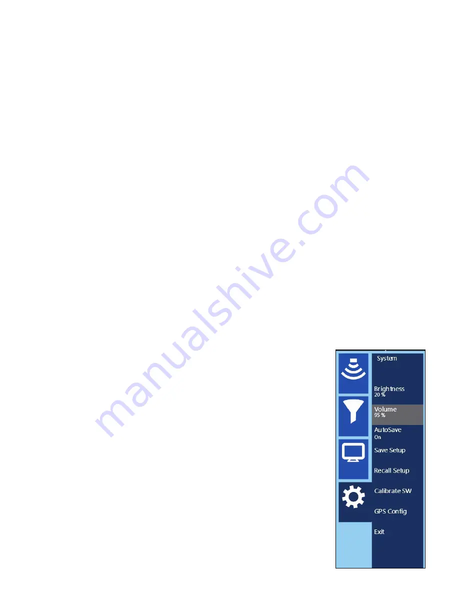
System Menu: 350HS and 300/800DF
1
AutoSave:
With AutoSave turned on you’ll automatically save every profile.
Select this option to save all of the files you collect, rather than be selective.
•
If performing real-time locating AutoSave may be beneficial as it will
decrease the number of selections required to clear your screen.
•
If collecting individual profiles to build into a 3D grid using software, we
recommend turning AutoSave Off. As you finish collecting one line this
pauses data collection while you get in position to start the next line.
2
Save Setup:
Once you’ve made all of the modifications to the settings listed
above, it’s a good idea to save your setup. This way you can recall it later if
you have to restart the system or if you know you’ll use these settings on a
regular basis.
3
Survey Wheel Calibration:
If you’re switching between different carts or
moving from one type of terrain to another you should recalibrate the survey
wheel in order to accurately track distance. To manually calibrate the antenna
you will need to lay out a measured line on your survey surface.
a)
Select Survey Wheel Mode: Quadrature or Pulse.
Summary of Contents for SIR 4000
Page 1: ......
Page 4: ......
Page 116: ...Geophysical Survey Systems Inc SIR 4000 Manual MN72 433 Rev F 110 ...
Page 140: ...Geophysical Survey Systems Inc SIR 4000 Manual MN72 433 Rev F 134 ...
Page 150: ...Geophysical Survey Systems Inc SIR 4000 Manual MN72 433 Rev F 144 ...
Page 156: ...Geophysical Survey Systems Inc SIR 4000 Manual MN72 433 Rev F 150 ...


