43
Fixed-wing models: receiver assignment
Installation notes
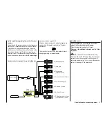
The servos MUST be connected to the receiver
outputs in the following order:
Outputs not required are simply left vacant.
Please note the following points in particular:
If you are using only one aileron servo, receiver out-
•
put 5 (right aileron) is left unused; it can also be used
for another purpose if you select “1 AIL” in the “
Basic
settings
” menu.
If you are using only one fl ap servo, receiver output 7
•
(right fl ap) MUST be left unused, assuming that you
have selected “
2 FL
” in the “
Basic settings
” menu.
Please also read the information on the following
pages.
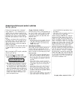
Receiver socket assignment for models with up to two ailerons and two fl aps, plus “normal” tail type, V-tail,
and two elevator servos (3 + 8)
Ser
v
o
4
8 V
C 57
7
B
es
N
r
4101
Receiver battery
Switch harness
Telemetry sensor
Y-lead,
Order No.
3936.11
Receiver
3 = Elevator / left V-tail
2 = Aileron / left aileron
8 = 2nd elevator / aux. function
7 = Right fl ap / reserve
5 = Right aileron / reserve
4 = Rudder / right V-tail
1 = Throttle / brake
6 = Flap / left fl ap / reserve
Summary of Contents for mx-16 HOTT
Page 7: ...7 For your notes...
Page 37: ...37 For your notes...
Page 41: ...41 For your notes...
Page 45: ...45 For your notes...
Page 51: ...51 For your notes...
Page 55: ...55 For your notes...
Page 81: ...81 For your notes...
Page 103: ...103 For your notes...
Page 133: ...133 For your notes...
Page 141: ...141 For your notes...
Page 161: ...161 For your notes...
Page 173: ...173 For your notes...

