background image

24

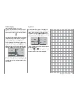
Description of transmitter - screen and keypad

Signal strength indicator 

Battery operating time

 since 

last battery charge, in hr:min

Screen and keypad

Flight timer

 in min:sec 

(count-up / count-down)

Stopwatch

 in min:sec 

(count-up / count-down)

Flight phase name

Switching between 
fl ight phases using switch

Receiver power supply voltage

Right-hand touch-key 

ef


cd


leaf through / alter values

SET

 Select / Confi rm

Model name

Model memory 1 … 20

Battery voltage and charge state in %

(If voltage falls below a particular level, a warning display 
appears - see pictures on right-hand page; at the same time 
a warning signal is emitted.)

Visual display of the trim lever positions; alternatively - if rota-
ry controls CTRL 7 … 9 are operated - display of the current 
settings of these two controls

Model type display

(fi xed-wing / helicopter)

Left-hand touch-key

ef


cd

 leaf through

ef

 pressed briefl y together: 

switches to Servo display 
menu

ESC

 = interrupt / back

ESC

 touched for about three 

seconds; Switches to the 
Telemetry menu, and 
back to the base display

See page 28 for possible warnings

Simultaneous brief press of 

ef

 or 

cd

 = 

CLEAR

Summary of Contents for mx-16 HOTT

Page 1: ...Programming Manual 33116 mx 16 HoTT 2 gb H O P P I N G T E L E M E T R Y T R A N S M I S S I O N mx 16...

Page 2: ...ging the stick mode 18 Description of transmitter 20 Transmitter controls 20 Rear of transmitter 21 Headphone socket 21 Mini USB socket 21 Data socket 21 DSC Direct Servo Control 22 Data storage card...

Page 3: ...r electric motor could burst into life accidentally if the receiving system is switched on when you are transmitting the transmitter To be on the safe side disconnect the fueltank or the flight batter...

Page 4: ...Secure the model adequately and ensure that no persons are standing in front of the model Carry out at least one complete function check on the ground followed by a complete simulated flight in order...

Page 5: ...motor If an RC system is to work correctly it is therefore important to suppress the electric motors and in electric powered models it is essential that every motor should be effec tively suppressed S...

Page 6: ...ompa nies so we are unable to state whether such parts can be used without incurring a safety risk Liability exclusion Compensation It is not possible for Graupner to ensure that the user observes the...

Page 7: ...7 For your notes...

Page 8: ...ctrolyte is corrosive do not allow it to contact skin or eyes In an emergency rinse the area immediately with plenty of clean water before seeking medical help The cells air vents must never be blocke...

Page 9: ...seful life Use your battery until its performance falls off or until the low voltage warning is triggered Caution When stored for a long period the cell voltage should not be allowed to fall below 1 2...

Page 10: ...wing the user to exploit all the options he needs in accordance with his experience in handling radio controlled models In theory the Graupner HoTT process allows more than 200 models to be operated s...

Page 11: ...iver Five different languages German and English subsequent software updates will offer French Italian and Spanish Ultra fast response times through direct ultra reliable data transmission from the ma...

Page 12: ...2roll 3sv 140 3sv 2nick pitch axis 4 SV 90 Swashplate limiter Servo travel adjustment 150 for all servo out puts variable separately for each side Single Side Servo Throw Variable sub trim range 125 f...

Page 13: ...ange approx 15 70 C Dimensions approx 46 x 21 x 14 mm Weight approx 12 g Set contents Order No 33116 mx 16 HoTT micro computer transmitter with integral 4NH 2000 RX RTU flat pack Ni MH transmitter bat...

Page 14: ...d are making really good contact Polarity of the mx 16 HoTT charge socket Commercially available battery charge leads produced by other manufacturers are often made up with the op posite polarity For...

Page 15: ...r battery is significantly higher than the last time it was switched on e g as a result of a charge process 01 0 00h stop flt 0 00 0 00 0 0V 6 1V 99 HoTT Mx CR 2032 lithium battery On the left hand si...

Page 16: ...charge current stated by the battery manufacturer The maximum charge current for the transmitter battery is 1 5 A Limit the charge current to this value on the charger If you wish to charge the trans...

Page 17: ...d After this use a PH1 size cross point screwdriver to undo the six screws recessed into the back panel of the transmitter as shown in the illustration Arrangement of the case back screws Hold the two...

Page 18: ...right below centre Turn this screw clockwise until the stick on that side moves freely from one end stop to the other alterna tively unscrew it until the stick is fully self centring again Do not tou...

Page 19: ...ght harder spring tension Turn to the left softer spring tension horizontal horizontal vertical vertical Note The right hand stick unit is of mirror image construction i e the screw you require is loc...

Page 20: ...y that the transmitter is perfectly balanced even when suspended from a neckstrap Order No 1121 Neckstrap 20 mm wide Order No 70 Neckstrap 30 mm wide 3 possition switch SW 6 7 Rotary proportional cont...

Page 21: ...guage for speech output is German For more information on this please refer to Voice messages in the HIDDEN MODE section starting on page 26 and the Teleme try section starting on page 130 The volume...

Page 22: ...ner sys tem ALWAYS 2 leave the transmitter s On Off switch in the OFF position when using a flight simulator and when using the mx 16 HoTT transmitter as a Pu pil unit in a Trainer system for only in...

Page 23: ...been named then you will find the associated log files in a sub folder named NoName when you remove the memory card from the transmitter and insert it in the card slot of a PC or laptop The data can...

Page 24: ...nd charge state in If voltage falls below a particular level a warning display appears see pictures on right hand page at the same time a warning signal is emitted Visual display of the trim lever pos...

Page 25: ...function menu and the menu lines within the set up menus in the same manner as the left hand touch key s arrow but tons 2 Selects and adjusts parameters in set up fields af ter you have activated them...

Page 26: ...sh The languages French Italian and Spanish will be made available later on the Download page of the transmitter at www graupner de in the form of an update VOICE MESSAGES As mentioned in the Headphon...

Page 27: ...s now loaded into the transmit ter s memory HIDDEN MODE CONTRAST LANGUAGE 0 ENGLISH VOICE ENGLISH 22 100 I The loading process is finished when the progress bar at the bottom edge of the screen disapp...

Page 28: ...section switched off Warnings The bottom line of the screen displays function fields which vary according to the menu selected SEL STO SYM ASY The function fields are activated by touching the SET but...

Page 29: ...01 3 33h stop flt 0 00 0 00 50 5 2V HoTT M About two seconds after you cease operating one of the two rotary controls the screen reverts to a display of the current position of the four trim levers fo...

Page 30: ...ound to a Graupner HoTT receiver but there is currently no connection with this receiver In our example we of course switched off the RF signal In contrast if you switch the transmitter on without swi...

Page 31: ...s by default this also helps to eliminate the danger of inadvertent ly using them incorrectly For the same reason virtually all the mixers are inactive by default For more details of this please refer...

Page 32: ...duct at www graupner de Note Once you have registered your transmitter at http graupner de de service produktregistrierung you will automatically be informed of new updates by e mail as they become av...

Page 33: ...iated model memory is ac tive then the LED lights up green after a short interval to indicate that your transmitter receiving system is ready for use once more Please note the following Resetting the...

Page 34: ...or your servos but only if the servo retaining screws are fitted and tight ened properly The drawing below shows how to in stall a servo correctly The brass spacers should be pushed into the rubber gr...

Page 35: ...ht install a Y lead Order No 3936 11 between lead and receiver as shown in the diagram below if you wish to use one or both of the receiver sockets to connect a servo speed controller etc The dual con...

Page 36: ...ems to Graupner HoTT receivers nor to those servos speed controllers gyros etc which are expressly approved for use at these higher voltages Please note however that virtually all servos speed control...

Page 37: ...37 For your notes...

Page 38: ...s affect the course of the signal after this point and it is possible and likely that there will be differences between the number of the transmitter control as stated above and the number of the subs...

Page 39: ...press the right hand touch key CLEAR button briefly Transmitter control switches Many functions are best controlled automatically by a particular freely programmable position of the Ch 1 transmitter...

Page 40: ...her feature in addition to cut off trim as described under Fixed wing models on the left this time in conjunction with the Throttle limit function see page 79 while the throttle limit slider is in the...

Page 41: ...41 For your notes...

Page 42: ...gram contains the appropriate mixer functions for the two servos Up to four flight phases can be programmed in each of the twenty model memories The digital trim positions are stored separately for ea...

Page 43: ...only one flap servo receiver output 7 right flap MUST be left unused assuming that you have selected 2 FL in the Basic settings menu Please also read the information on the following pages Receiver s...

Page 44: ...problem Model type Servo rotating in wrong direction Remedy V tail Rudder and elevator reversed Reverse servos 3 4 in the servo set menu Rudder correct elevator reversed Swap over servos 3 4 at the r...

Page 45: ...45 For your notes...

Page 46: ...ned to inputs 5 8 in virtually any order This is carried out in the Transmitter control settings menu In addition to three linear mixers which can be assigned to any functions and can also be switched...

Page 47: ...eans that you can easily skip irrelevant menus when programming a model helicopter Installation notes The servos MUST be connected to the receiver outputs in the order shown on this page Outputs not r...

Page 48: ...the Fixed wing model model type and the receiver supplied in the set is bound to it This is indicated by the receiver code displayed at top right of the screen in the example above this is R08 If on t...

Page 49: ...choice by switching the transmitter off If you wish to remove a model memory which you inadvertently occupied you can simply erase it from a different model mem ory However if you erase a model memor...

Page 50: ...to use a newly initialised model memory then this MUST first be bound to a further receiver before any servos connected to the receiver can be con trolled from the transmitter For more information on...

Page 51: ...51 For your notes...

Page 52: ...import from SD Use the arrow buttons cd of the left or right hand touch key to select the clear model sub menu then touch the SET button Select the model to be erased using the arrow buttons cd of th...

Page 53: ...will be required to define the model type Helicopter or Fixed wing immediately However if you erase a non active model memory then the message free appears in the Model select menu copy model model U...

Page 54: ...copy mod mod export to SD import from SD Use the arrow buttons cd of the left or right hand touch key to select the model to be imported from the SD memory card EXTRA ALPINA COBRA BELL47G import from...

Page 55: ...55 For your notes...

Page 56: ...Throttle at left stick MODE 1 Throttle at right stick elev down elev up left rudder right rudder full throttle idle left aileron right aileron full throttle left rudder right rudder idle elev down el...

Page 57: ...abled no The brake system is retracted in the for ward position of the throttle brake stick In the Wing mixer menu the Brake NN mixers are activated The throttle warning message Throttle too high see...

Page 58: ...dder functions are operated by two control surfaces set in a V shape each controlled by a separate servo The two way coupling function for the rudder and elevator control systems is automatically carr...

Page 59: ...ue by briefly pressing the cd or ef buttons of the right hand touch key CLEAR Switching between count up and count down Count up timer stopwatch function If you assign a switch and start the stopwatch...

Page 60: ...active For example this would be phase 2 if one of the switches assigned to phase 3 or 4 is also closed or phase 3 if the switches assigned to phases 3 and 4 are closed As a result you may wish to tak...

Page 61: ...afe in this respect Otherwise you risk a failed connection to the down link channel and consequent malfunctions Binding multiple receivers to one model If necessary it is possible to bind more than on...

Page 62: ...er s output power is significantly reduced and the blue LED on the aerial base starts to flash At the same time the time display on the transmitter screen starts counting down and a double beep sounds...

Page 63: ...wing model phase 4 landing 6 receiv out rx bind R08 range test 99sec RF transmit OFF Now you can use the right hand arrow buttons to switch between OFF and ON Touch the central SET button of the right...

Page 64: ...ck mode Basically there are four possible ways of arranging the principal control functions of a model helicopter on the two dual axis sticks the primary functions are roll pitch axis tail rotor and t...

Page 65: ...e as above but rotated through 90 i e one roll servo on one side and two pitch axis servos front and rear 4sv 90 Four point swashplate linkage using two roll and two pitch axis servos Simultaneously p...

Page 66: ...rotation left hand rotation The program requires this information in order to set up the mixers to work in the correct sense this applies to the mixers which compensate for rotor torque and motor pow...

Page 67: ...timers are shown in the basic display one stop watch and one flight timer STARLET 02 0 00h stop flt 0 00 0 00 0 0V 6 1V HoTT M 99 A physical switch or a control switch e g the control switch G3 locate...

Page 68: ...buttons of the right hand touch key CLEAR after you have halted the timer Note A count down timer is indicated in the basic display by a flashing colon between the minutes field and the seconds field...

Page 69: ...to the original default receiver socket sequence Typical application In the helicopter program of the mx 16 HoTT the outputs for one collective pitch servo and the throttle servo have been interchang...

Page 70: ...a further three seconds You can now release the SET button on the receiver The receiver is in Bind mode as long as the LED flashes red green Briefly touch the central SET button of the right hand tou...

Page 71: ...nterference rejection Walk further away from the model until you no longer 8 have full control over it At this point wait until the test period has elapsed 9 with the model still switched on and ready...

Page 72: ...m as and when necessary The direction of rotation is indicated by the symbols and Be sure to set the direction of servo rotation before you make adjustments to the remaining options Simultaneously pre...

Page 73: ...ransmitter control stick rotary proportional knob or switch to the side to be adjusted so that the marking frame only encloses the value you wish to change Touch the central SET button of the right ha...

Page 74: ...by mistake unless it is inactive i e unless no function is assi gned to it That is why you can select these supplementary trans mitter controls with complete freedom in the Transmitter control setting...

Page 75: ...transmitter control rotary proportional controls CTRL 6 8 or switches 4 5 and 6 7 to a position at which the marking frame encloses both sides of the travel setting I5 I6 I7 trv 3 I8 ctrl 7 free free...

Page 76: ...tary transmitter controls for any task you like and that you are not required deliberately to program away the transmitter controls which are not required for a particular model Any superfluous transm...

Page 77: ...R 10 provide a centre position in addition to the two end points Simultaneously pressing the cd or ef buttons of the right hand touch key CLEAR with the switch assign ment activated see illustration a...

Page 78: ...ld only unnecessarily confuse this complex mixer system For this reason the Throttle input MUST always be left free when you are programming a model helicopter Gyr trv I5 thr gyr I8 lim 100 3 100 100...

Page 79: ...n electric motor directly At the other extreme the throttle servo or speed controller can of course only reach its full throttle position if you release full servo travel using the throttle limit cont...

Page 80: ...r off direction the illustration above changes if you alter the transmitter control direction for the collective pitch minimum position of the Ch 1 stick from back reflected in the picture above to fo...

Page 81: ...81 For your notes...

Page 82: ...rol surface declines steadily towards the extremes dependent upon the position of the linkage point on the output disc or lever You can compensate for this effect by setting an Expo value greater than...

Page 83: ...set the values for each of the two switch positions sepa rately in the highlighted field using the arrow buttons of the right hand touch key Simultaneously touching the cd or ef buttons of the right...

Page 84: ...value greater than 0 with the result that the angular travel of the output device increases disproportionately as stick travel increases Like Dual Rates the Expo setting applies directly to the corres...

Page 85: ...wish to switch between two settings use the f button of the left or right hand touch key to move to the right hand column marked at the bottom edge of the screen with the switch symbol then briefly t...

Page 86: ...touch key and selecting one of the following names in the highlighted field using the arrow buttons of the right hand touch key take off thermal If you have not assigned a switch to phases 2 3 and 4 i...

Page 87: ...y with a transition time of around one second With this option which works in a similar way to trans mitter control sub trim or offset settings with other radio control systems it is possible to set v...

Page 88: ...arious control systems e g to link the ailerons and rudder or to inter connect a pair of servos where two control surfaces are actuated by separate servos In all these cases the signal which flows dir...

Page 89: ...uch more pronounced in model gliders with high aspect ratio wings than in power models with their much shorter moment arms and usually has to be countered by giving a simultaneous rudder deflection in...

Page 90: ...ot usu ally necessary if the correct channels are used diff flaps Camber changing flap differential The aileron flap mixer see below is designed to superimpose an aileron function on the flaps Flap di...

Page 91: ...to 150 Simultaneously pressing the cd or ef buttons of the right hand touch key CLEAR resets an altered value to 0 Usual values are generally in single to low double figures It is essential to check a...

Page 92: ...the extreme up deflection of the ailerons in the butterfly setting because the differential travel reduces or entirely suppresses the down aileron de flection However the up travel of the ailerons is...

Page 93: ...the flap positions then you should leave the value for this mixer at 0 See the notes on page 89 in this regard diff red Differential reduction The problem of reduced aileron response in the but terfly...

Page 94: ...ottle and Ch 1 tail rotor are not required for the Auto rotation flight phase described in the section starting on page 104 instead they are automatically switched to a user varia ble pre defined valu...

Page 95: ...urve is termed the Output and this point can be varied within the range 125 and 125 at a maximum of five reference points The control signal modified in this way affects the collective pitch servos on...

Page 96: ...d at the centre of the stick travel and the throttle setting should be adjusted relative to the collective pitch curve in such a way that the correct system rotational speed is obtained at this point...

Page 97: ...ariable pre set value see the section starting on page 104 Helicopter with speed GOVERNOR REGULATOR In contrast to speed controllers which simply adjust pow er output in the same way as a carburettor...

Page 98: ...erating mode or if the gyro only offers normal mode then you should set up the mixer as follows The tail rotor control curve can be defined using up to five points in a similar way to the collective p...

Page 99: ...nce with the instructions supplied with the governor you intend to use However it is more convenient and also safer to adopt the method described on the preceding double page using the Ch1 thro mixer...

Page 100: ...uced collective pitch and for aerobatics The diagram shows a curve with a slightly altered throttle setting below the hover point at the cen tre of stick travel 100 100 OUTPUT 2 3 4 5 1 Control travel...

Page 101: ...hrottle graphic page increase the value at Point 3 100 100 OUTPUT 2 3 4 5 1 Control travel Hover point b Rotational speed too high Remedy on the Collec tive pitch graphic page increase the blade pitch...

Page 102: ...box or even the motor itself is negligible compared with the damage which a model helicopter can cause if its spinning rotor blades are allowed to wreak havoc Make sure that nobody else is standing in...

Page 103: ...103 For your notes...

Page 104: ...g off it is necessary to set a greater maximum collective pitch value Touch the central SET button of the right hand touch key to select the graph page of Collective pitch and then move the vertical l...

Page 105: ...principle i e it is not driven by the motor and therefore there is no torque effect for which compensation is required i e which the tail rotor would have to correct For this reason all the appropriat...

Page 106: ...hes can potentially be assigned you should take care not to as sign dual functions to particular switches accidentally The two important mixer parameters are as follows the mixer ratio which defines t...

Page 107: ...key the input field in the column marked fro m at the bottom edge of the screen is now high lighted black background Use the arrow buttons of the right hand touch key to 3 define the mixer input fro...

Page 108: ...to remember that the mixed travels of the individual mixers are cumulative when multiple stick commands are made simultaneously and this brings a danger that the servo concerned may strike its mechani...

Page 109: ...values In the next section we will describe a typical practical application by defining a linear mixer curve intended to solve the following problem We have a powered model with two flap servos conne...

Page 110: ...arrow buttons cd or ef of the right hand touch key CLEAR Symmetrical mixer ratios The next step is to define the mixer values above and below the mixer neutral point starting from its current position...

Page 111: ...elevator during the tow You now wish to set the elevator servo connected to receiver output 3 to slight up trim when the tow release is closed In the screen display familiar from page 107 we have set...

Page 112: ...wash plate linkages employing 2 4 collective pitch servos the mixer ratios and directions are set up by default as can be seen in the screen shot above The pre set value is 61 in each case but the val...

Page 113: ...to 150 of normal travel 0 corresponds exactly to the servo centre position The servo display provides a quick method of checking your settings with out having to switch on the receiving system However...

Page 114: ...ts power is to be drawn from a four cell NiMH battery or a single cell LiPo battery The voltage range offered in the next line Battery warning threshold will vary according to this setting Simultaneou...

Page 115: ...tting Batt warning Contrast Touch Sense 4 7v 0 2 Display light unlim RF Country Euro The purpose of the country setting is to fulfil the require ments of various directives FCC ETSI IC etc For example...

Page 116: ...tion Pos if interfer 2 ence occurs after a delay time has elapsed Use the arrow buttons ef of the left or right hand touch key to select the desired servo socket 1 to 8 z then touch the central SET bu...

Page 117: ...ch you enter using the Telemetry menu such as Fail Safe servo direction servo trav el mixer and curve settings etc are stored exclu sively in the receiver and are therefore carried over if you install...

Page 118: ...tton of the right hand touch key to highlight the parameter black background Change the value within the possible range using the arrow buttons of the right hand touch key and then press the SET butto...

Page 119: ...an still be operated safely at this point Nevertheless in the interests of safety the distance to the model should be reduced until the audible warning ceases Receiver temperature R TEM Ensure under a...

Page 120: ...mit ter control to the desired position and touch the SET button again to store the current transmitter control position This position is now stored as the new neutral position TRIM trim position The...

Page 121: ...ble to operate each aileron with two servos or to control an oversized rudder using two coupled servos instead of a single one Sharing control functions amongst multiple HoTT receiv ers is a useful id...

Page 122: ...signal should be interrupted This setting applies to all channels but only affects the servos programmed to FAIL SAFE mode Default setting 0 75 s FAIL SAFE ALL global fail safe setting This sub menu c...

Page 123: ...VEL 100 MIXER 1 RX WING MIXER TAIL TYPE NORMAL Value Explanation Possible settings MIXER Mixer select 1 2 or 3 MASTER CH Primary channel 0 1 8 SLAVE CH Secondary channel 0 1 according to receiver S TR...

Page 124: ...cording to receiver TYPE Curve type A B C see illustration Servo travel Transmitter control travel Expo 100 100 100 0 100 100 0 Servo travel Transmitter control travel Expo 100 TYPE A 100 100 0 100 10...

Page 125: ...e you can set the maximum servo travel for the servo test on the plus side of control travel 2000 s corresponds to full travel 1500 s corresponds to the neutral position ALL MIN minimum servo travel I...

Page 126: ...y where multiple servos are employed for a single function e g ailerons to ensure that the groups of servos run absolutely synchronously If you are using digital servos we recommend that you set 10 ms...

Page 127: ...similar problem with the result that sporadic range problems might be expected For this reason it is essential to connect the most im portant control functions to the primary receiver the one program...

Page 128: ...rating voltage in Volt since the last time it was switched on TMP The thermometer indicates the receiver s current operating temperature RX GENERAL MODUL 0 0V BAT1 BAT2 0 0V T2 20 C T1 20 C E FUEL F C...

Page 129: ...he climb descent of the model in m 1sec and m 3sec the centre of the screen also displays the current actually being drawn from a power source At the right hand edge the screen shows an alternating di...

Page 130: ...Select the desired menu line with the arrow buttons cd of the left or right hand touch key TELEMETRY SETTING DATA VIEW SIMPLE DATA VIEW RF STATUS VIEW VOICE TRIGGER and then press the central SET butt...

Page 131: ...cle through the speech outputs selected under the TRANSFER RECEIVER and SENSOR options as described in the following section VOICE TRIGGER TRIG TRANSFER RECEIVER 9 3 REPEAT 1SEC VARIO VARIO If you ass...

Page 132: ...on of the right hand touch key TEMP STRENGTH VOLT LOWVOLT SENSOR This line only appears if you have already activated one of the RX sub menus of the SIMPLE DATA VIEW menu and then returned directly to...

Page 133: ...133 For your notes...

Page 134: ...en the Train er connection is switched off Use the arrow buttons ef of the left or right hand touch key to select the transmitter controls 1 to 8 z to be transferred to the pupil and briefly press the...

Page 135: ...an mc or mx series transmitter it is best to set up a free model memory in the Pupil transmitter with the required model type Fixed wing or Helicopter Assign the model name Pupil to the memory and set...

Page 136: ...transmitter which replaces the RF module is not connected correctly Incorrect cable connection see next section for cable selection Pupil transmitter not set to PPM 10 18 24 mode Further possible err...

Page 137: ...HoTT mx 22 iFS mx 24s and if fitted with DSC socket Order No 3290 24 mc 19 s iFS mc 22 s iFS and mc 24 mc 19 to mc 24 mx 22 iFS mx 24s mitter Pupil transmitter with DSC socket Pupil transmitter with...

Page 138: ...during the following procedure servo set D R expo wing mixer contr set phase trim free mixer servo disp basic sett fail safe telemetry info disp teach pupi servo set D R expo free mixer contr set heli...

Page 139: ...right T 1 2 3 4 5 6 7 8 P BIND SW N A 9 TRAINER Teach Binding the Pupil transmitter to theTeacher trans mitter Note During the binding procedure the distance between the two transmitters should not b...

Page 140: ...flashes in the basic transmitter display and relatively quiet audible signals are heard GRAUBELE 01 2 22h stop flt normal 0 00 0 00 5 5V 51 5 2V HoTT P RFC Teach then this indicates that the Pupil si...

Page 141: ...141 For your notes...

Page 142: ...so that it is able at any time to identify the radio signals of its transmitter Version RFID firmware ver date time SD CARD FRI 1 11 0KB ABCDEF12 2011 03 11 11 22 33s This line displays the version nu...

Page 143: ...s due to power failure for example when the battery is swapped by a user replaceable buffer battery SD card RFID firmware ver date time SD CARD FRI 1 11 2048KB ABCDEF12 2011 03 11 11 22 33s This line...

Page 144: ...both of them down and as air brakes by deflecting both of them up simply by setting up a suitable mixer see the section starting on the next double page Such systems are generally more often used in g...

Page 145: ...ty reasons you will also see a warning message and hear an audible warning if you switch the transmitter on with the throttle stick positioned towards full throttle but only if you have already set th...

Page 146: ...ppropriate message not possible now voltage too low Once you have overcome this initial hurdle you may need to bind the receiver installed in the model to this model memory in the Basic settings menu...

Page 147: ...servo or left flap servo Rudder servo or V tail Aileron servo or left aileron servo Elevator servo or V tail Right aileron servo Auxiliary function Receiver power supply Notes If you set up a V tail b...

Page 148: ...ble to switch this function off particularly if you have ambitions as an aerobatic pilot this is done by assigning a physical switch to the mixer for example the writer switches this mixer off automat...

Page 149: ...ing of multi flap wing systems and are largely self explanatory When you have completed the model specific settings up to this point you are probably ready to consider the model s first flight At this...

Page 150: ...o mod name stick mode CH8 delay motor at C1 1 no tail type normal GRAUBELE no Example 1 Using one of the rotary proportional controls CTRL 6 8 If one of these transmitter controls is used the set up i...

Page 151: ...in the Basic settings menu and if you have not connected any other auxiliary function then this would be channel 6 if your model features two aileron servos and two flap servos then channel 8 would b...

Page 152: ...ichever arrangement you prefer However the following section assumes that both OFF positions will be set to for ward If you prefer the alternative arrangement there is no problem the only difference c...

Page 153: ...touching the central SET button of the right hand touch key and moving the switch from forward to back i e towards you With the mixer switched on move to the column above the f symbol using the arrow...

Page 154: ...e stick movement or the other way round when the switch is operated the latter stay at around the mid point and only the Channel 1 display moves 1 3 5 7 2 4 6 8 0 0 0 100 0 88 0 88 1 3 5 7 2 4 6 8 0 0...

Page 155: ...ers with the same switching direction so that they start running at the same moment you turn the motor on In contrast if you have decided on the solution de scribed in Example 1 then unfortunately the...

Page 156: ...rward from the centre position while Phase 3 is back towards you Select the appropriate line name and switch assign ment in the usual way i e using the various touch keys 5 00 2 4 5 aile flap 2ail2fl...

Page 157: ...or at C1 1 idle re tail type cut off 150 100 2elev sv and set 2elev sv in the tail type line The two elevator servos are then connected to receiver output sockets 3 and 8 Two rudder servos In this exa...

Page 158: ...gura tion the normal servo sequence has proved useful this arrangement can also be used for canards Airbrakes or throttle or speed controller electric motor Right flap elevator Left flap elevator Rudd...

Page 159: ...nly appear in the list if you have also entered 2fl in the aile flap line at the Delta Flying wing model type see illus tration on the right In principle the same applies to the Brake NN mixers These...

Page 160: ...pro duces an up elevator effect deflecting them up creates the opposite effect In contrast the outboard ailerons act in the reverse direction a down deflection produces a down elevator effect and vic...

Page 161: ...161 For your notes...

Page 162: ...itches without a centre detent SW 3 or SW 8 An optional extra used only if necessary is mixture adjustment control for the carburettor This is generally operated by one of the rotary proportional cont...

Page 163: ...ion of effect Touch the central SET button of the right hand touch key to move to the mixer inputs on the second screen page and set the appropriate mixer ratios In both cases the mixer neutral point...

Page 164: ...tudinal axis aileron MIX rd al ASYmmetrical setting The exact values required must be found by flight testing In most cases relatively small mixer values are called for typically below 10 but this doe...

Page 165: ...suffer interference for a while In the receiver s default state however the servos remain in their last valid position hold mode when in terference occurs You can program any individual servo output...

Page 166: ...want to forfeit all the possible refinement facilities after the basic description you will also find set up notes on gyro gain speed governors and flight phase programming Note If in contrast to the...

Page 167: ...0 STARLET In the next four lines we come to the first settings which are specific to helicopters In the Swashplate type line select the number of servos which are used to actuate the swashplate See pa...

Page 168: ...100 100 100 0 0 100 100 100 100 S4 S5 where you can set up the travels and directions of rotation of the individual servos The basic aim here should be to keep servo travels at 100 wherever possible a...

Page 169: ...complexity is just what you don t need at the moment The reference point for hovering should generally be the mechanical centre point of the collective pitch stick as this position feels completely n...

Page 170: ...ou should set a value of around 125 or 125 depending on the direction of servo rotation tail ptch thro Autorot gyro 0 inp8 0 0 125 This setting ensures that the motor stops reliably in the auto rotati...

Page 171: ...eds and trim set ups you will need to activate a series of flight phases which can be called up via switches which you assign The first step in this process is to call up the Basic model settings menu...

Page 172: ...acilities to allow you to implement different rotational speeds in the individual flight phases A practical suggestion which includes the throttle limiter function can be found in the section starting...

Page 173: ...173 For your notes...
Page 174: ...Appendix Graupner HoTT Vario module Order No 33601 Vario with altitude signals and five different tones for climb and descent altitude display and storage of min and max altitude Additional warning th...

Page 175: ...l cell measurement with min voltage warning thresholds Voltage current and capacity measurement with warning thresholds for min and max voltage max capacity and max current Rev count measurement and p...

Page 176: ...to mount the unit on the support bars of hand held transmitters allowing you to position it in such a way that you can read off telemetry data in real time while you control your model The user update...

Page 177: ...Angewendete harmonisierte Normen Harmonised standards applied EN 60950 2006 EN 301 489 1 V1 7 1 EN 301 489 3 V1 4 1 EN 300 328 V1 7 1 Health and safety requirements pursuant to 3 1 1 Article 3 1 a Pr...

Page 178: ...ses and can radiate radio frequency energy and if not installed and used in accordance with the instruc tions may cause harmful interference to radio communi cations However there is no guarantee that...

Page 179: ...stunsanspr che des Verbrauchers werden durch diese Garantie nicht ber hrt Bitte berpr fen Sie vor einer Reklamation oder R cksendung das Produkt genau auf M ngel da wir Ihnen bei M ngelfreiheit die en...

Page 180: ...form you of your nearest stockist We accept no liability for printing errors Printed in Germany PN PE 02 Although we have carefully checked the information contained in these instructions and checked...

Reviews: