2-14
Data subject to change without notice 7/07. © 2007 GE Drives
(2) Digital input terminals (FWD, REV, X1 to X9, PLC,
and CM)
1.
Digital input terminals (e.g., FWD, REV, X1 to X9) are
generally turned on or off by connecting or discon-
necting the line to or from the CM terminal.
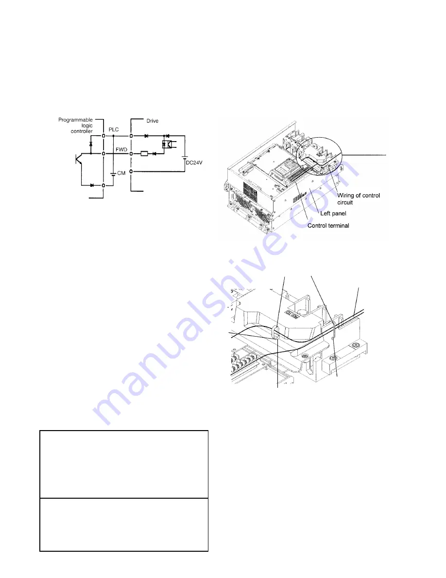
If digital input terminals are turned on or off by
switching the PLC’s open collector output using an
external power supply, a resulting bypass circuit may
cause the drive to malfunction. To prevent a malfunc-
tion, connect the PLC terminal as shown in Fig. 2-3-
11.
Fig. 2-3-12 The Control Wiring Route
Fig. 2-3-13 Securing Positions for Inverter Control Circuit Wiring (40 HP or more)
Fig. 2-3-11 Prevention of Bypass Current by External Power
2.
When using a contact input, a high-quality relay with
reliable contacts must be used.
(3) Transistor output terminals (Y1 to Y4, CMY)
1.
These terminals have a circuit configuration as shown
in Table 2-3-3, "Transistor Output". Confirm the
polarity of the external power supply.
2.
To connect a control relay, connect a surge absorbing
diode to both ends of its exciting coil.
(4) Sink or Source Logic Selection.
1.
Set SWI for Sink or Source Connection to the PLC.
The factory default setting is Sink and this instruction
manual explains Sink logic function only.
2.
When you need to connect source type logic, refer to
Basic Connection Diagram Fig. 2-3-3 and Fig. 2-3-4
and Technical Information Manual. (Sink Logic is
commonly used in the USA and Source Logic is
commonly used in Europe.)
(5) Others
1.
To prevent a malfunction as a result of noise, control
terminal cables must be placed as far as possible
from the main circuit cables.
2.
The control cables inside the inverter must be
secured to prevent direct contact with the main circuit
(e.g., main circuit terminal block).
wiring
Cable ties
Cable
binding
Hole A
Cable binding
Hole B
(6) Wiring of control circuit (inverter of 40 Hp or more)
1.
Pull out the control circuit wiring along the left panel
as shown in Fig. 2-3-12.
2.
Secure the cable to cable binding hole A (on the left
wall of the main circuit terminal block) using a cable-
tie
(e.g., Insulock). The cable-tie must not exceed 0.14"
(3.5mm) in width and 0.06" (1.5mm) in thickness.
3.
When the optional PC board is mounted, the signal
lines must be secured to cable binding hole B.
WARNING
Control lines generally do not have enhanced
insulation. If the insulation of a control line is
damaged, the control signals may be exposed to
high voltage in the main circuit. The Low Voltage
Directive in Europe also restricts the exposure to
high voltage. Electric shock may result
CAUTION
The inverter, motor, and cables generate noise.
Check that the ambient sensors and devices do
not malfunction. Accident may result.
Summary of Contents for AF-300 P11
Page 1: ...GE Consumer Industrial AF 300 P11 User s Guide ...
Page 35: ...2 18 Data subject to change without notice 7 07 2007 GE Drives Notes ...
Page 37: ...3 2 Data subject to change without notice 7 07 2007 GE Drives Notes ...
Page 53: ...4 16 Data subject to change without notice 7 07 2007 GE Drives Notes ...
Page 62: ...5 9 Frequency Setting Block Diagram ...
Page 66: ...5 13 ...
Page 84: ...5 31 Notes ...
Page 99: ...5 46 Notes ...
Page 109: ...7 8 Data subject to change without notice 7 07 2007 GE Drives Notes ...
Page 115: ...8 6 Data subject to change without notice 7 07 2007 GE Drives Notes ...
Page 123: ...10 6 Data subject to change without notice 7 07 2007 GE Drives Notes ...


