


2-36
Chapter 2
3. Function Explanation
■
H15 Auto-restart (Holding DC voltage)
This function is for when 2 (deceleration-to-stop at power
failure) or 3 (operation continuation) is set to “F14 Restart
mode after momentary power failure .” Either function starts a
control operation if the DC link circuit voltage drops below the
set operation continuation level.
- Setting range 230V: 200 to 300V
460V: 400 to 600V
When power supply voltage to the inverter is high, control can
be stabilized even under an excessive load by raising the
operation continuation level. However, when the level is too
high, this function activates during normal operation and
causes unexpected motion. Please contact Fuji electric when
changing the initial value.
■
H16 Auto-restart (OPR command self-hold time)
As the power to an external operation circuit (relay sequence)
and the main power to the inverter is generally cut off at a
power failure, the operation command issued to the inverter is
also cut off. This function sets the time an operation com-
mand is to be held in the inverter. If a power failure lasts
beyond the self-hold time, power-off is assumed, automatic
restart mode is released, and the inverter starts operation at
normal mode when power is applied again. (This time can be
considered the allowable power failure time.)
- Setting range: 0.0 to 30.0s, 999
When 999 is set, an operation command is held (i.e., consid-
ered a momentary power failure) while control power in the
inverter is being established or until the DC link circuit voltage
is about 0.
■
H18 Torque control
This function controls motor torque according to a command
value.
The torque command value is +200% when the voltage at
terminal 12 is +10V and is -200% when the voltage is -10V.
H15
HOLD V
H18
TRQ CTRL
H16
SELFHOLD t
Set value
Operation
0
Inactive (operation by frequency command)
1
Torque control active
A 0 to +10 V analog voltage input to terminal 12 and the
direction of rotation (FWD or REV) is used for the torque
command value. 0 is used for 0 to -10V.
2
Torque control active
A -10 to +10V analog voltage input to terminal 12 and
the direction of rotation (FWD or REV) is used for the
torque command value.
• In torque control, the torque command value and motor load
determine the speed and direction of rotation.
• When the torque is controlled, the upper limit of frequency
refers to the minimum value among the maximum frequency,
the frequency limiter (High) value, and 120Hz. Maintain the
frequency at least one-tenth of the base frequency because
torque control performance deteriorates at lower frequencies.
• If the operation command goes off during a torque control
operation, the operation is switched to speed control and the
motor decelerates-to-stop. At this time, the torque control
function does not operate.
■
H19 Active drive
This function automatically extends accelerating time against
acceleration operation of 60 seconds or longer to prevent an
inverter trip resulting from a temperature rise in inverter due to
overcurrent.
- Set value 0: Inactive
1: Active
(When the active drive function is activated, the acceleration
time is three times the selected time.)
■
H20 PID control (Mode select)
to
■
H25 PID control (Feedback filter)
PID control detects the amount of control (feedback amount)
from a sensor of the control target, then compares it with the
reference value (e.g., reference temperature). If the values
differ, this function performs a control to eliminate the devia-
tion. In other words, this control matches the feedback
amount with the reference value.
This function can be used for flow control, pressure control,
temperature control, and other process controls.
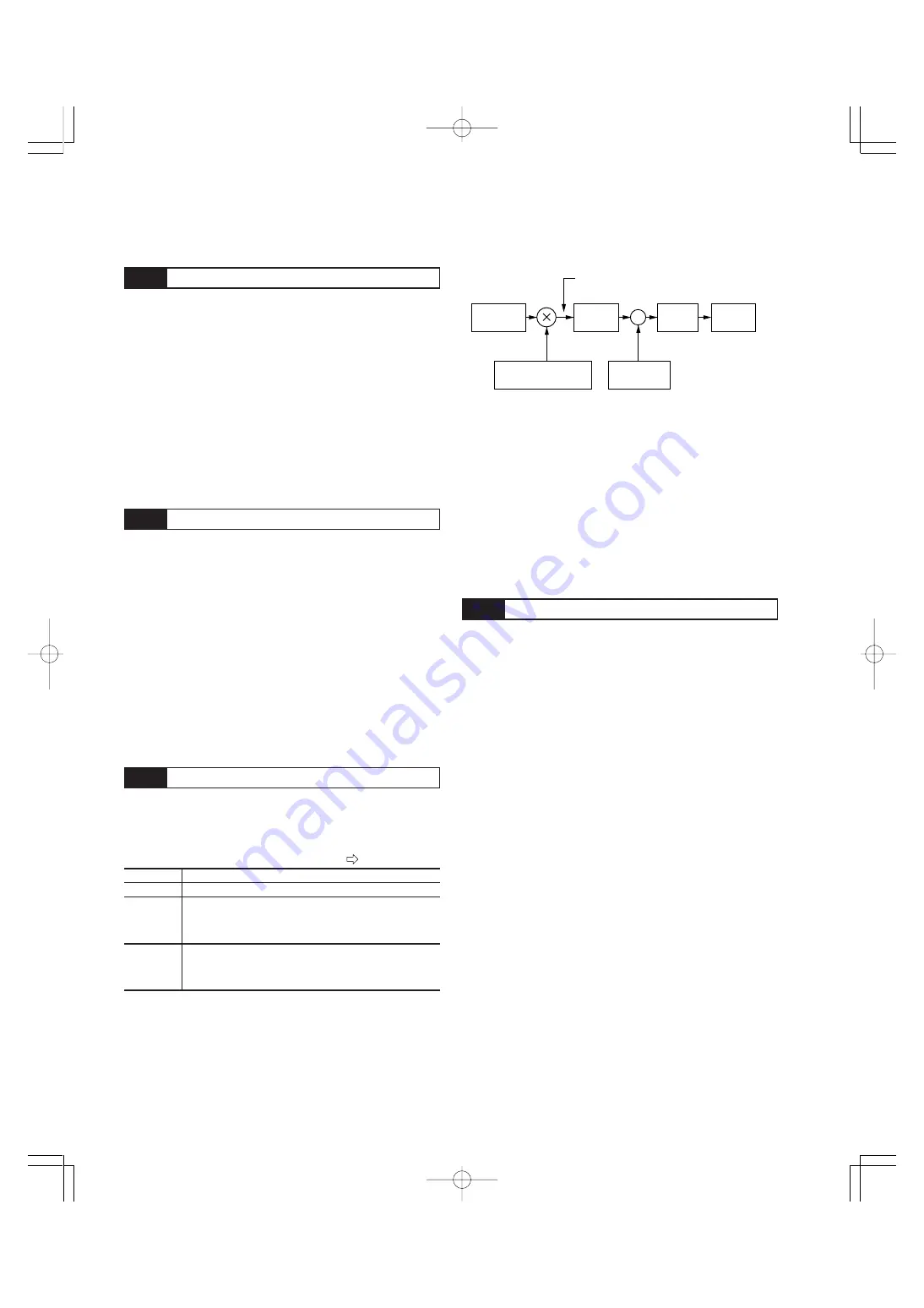
Torque control block diagram
+
—
Torque command value
Voltage at
terminal 12
Torque
limitation
Output
frequency
1: Forward command
- 1:Reverse command
Regulator
Detected
torque current
H19
AUTO RED
E01 to E09 : 23
Chapter02J(P26˜43).p65
07.8.9, 12:26
Page 36
Adobe PageMaker 6.5J/PPC
Summary of Contents for FRENIC5000G11S Series
Page 1: ......
Page 2: ......
Page 154: ...3 30 3 12 13 P23 30 65p 07 8 9 12 34 Page 30 Adobe PageMaker 6 5J PPC...
Page 166: ...4 12...
Page 182: ...3 12 13 P23 30 65p 07 8 9 12 34 Page 30 Adobe PageMaker 6 5J PPC 5 16...
Page 212: ...3 12 13 P23 30 65p 07 8 9 12 34 Page 30 Adobe PageMaker 6 5J PPC 6 30...
Page 234: ...MEMO Chapter8 4 P15 p65 07 8 9 12 57 Page 18 Adobe PageMaker 6 5J PPC...
Page 235: ......
Page 236: ......


