


Chapter 4
1. Inverter and Motor Selection
4-6
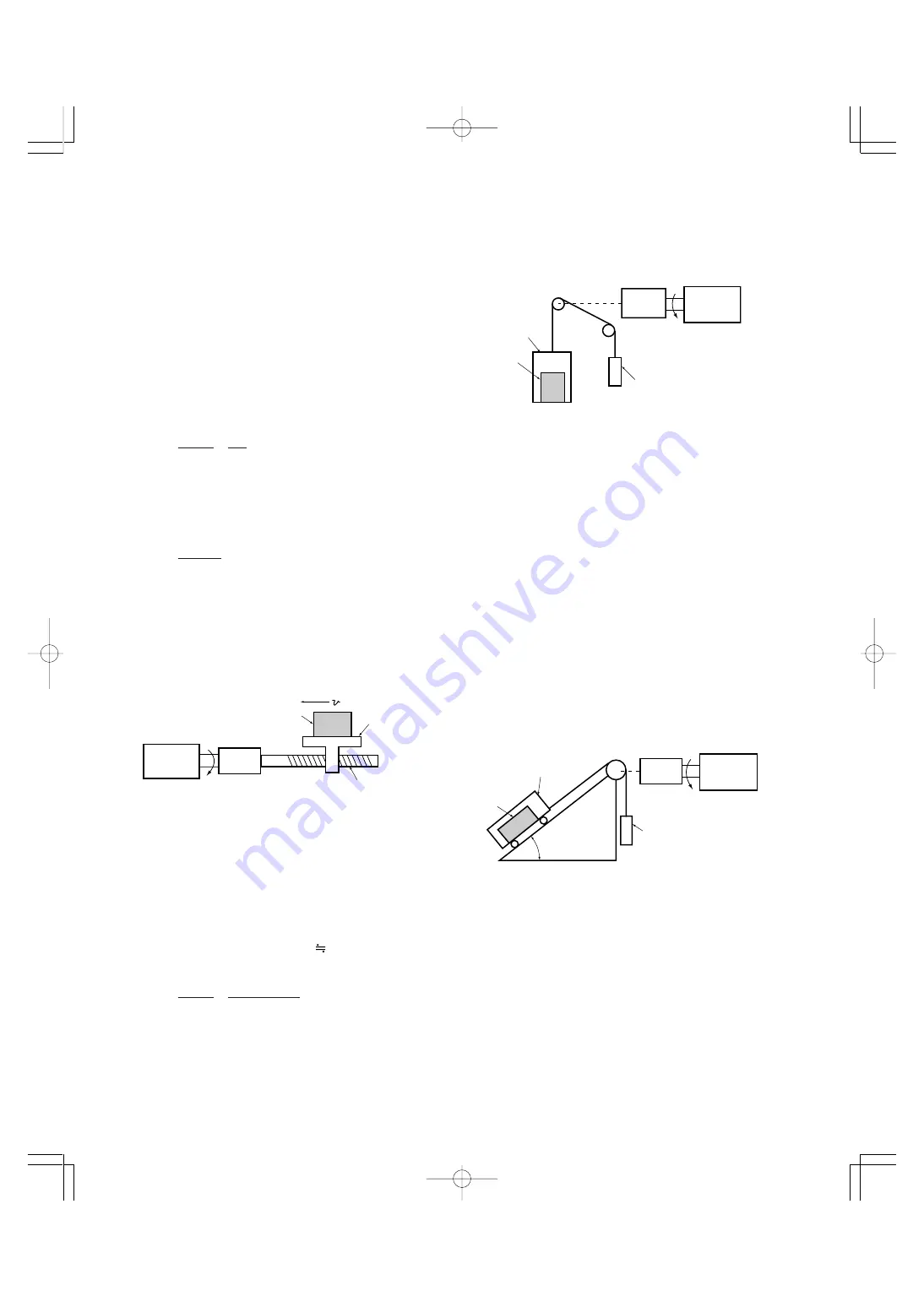
(2) Moving a load vertically
As shown in Fig. 4.8, where a cage weight, load weight,
and balance-mass weight are W
0
, W, and W
B
[kg], the
force of gravity F [N] is as follows:
(Lifting)
F = (W
0
+ W – W
B
) · g
[N] ...................................... (4.5)
(Lowering)
F = (W
B
+ W – W
0
) · g
[N] ...................................... (4.6)
Where maximum load is W
max
, generally W
B
equals to
(W
o
+ W
max
) / 2. So, F may become a negative force to
brake both lifting and lowering movements depending on
the load weight.
Calculate the required torque
τ
around the motor shaft in
the driving mode by expression (4.1) and that in the
braking mode by expression (4.2). That is, if F is positive,
use expression (4.1); if it is negative, use expression
(4.2).
(3) Moving a load along a slope
Lifting and lowering a load along a slope may seem to be
like lifting and lowering a load vertically, but friction force
between the load and the slope cannot be ignored in
lifting and lowering along a slope. Therefore, the expres-
sion for lifting a load is a little different from that for
lowering a load. Where slope angle is
θ
and friction
coefficient is
µ
, as shown in Fig. 4.9, driving force F [N] is
as follows:
(Lifting)
F= ((W
0
+ W)(sin
θ
+
µ
· cos
θ
) – W
B
) · g
[N] ............... (4.7)
(Lowering)
F=(W
B
– (W
0
+ W)(sin
θ
–
µ
· cos
θ
)) · g
[N] ............... (4.8)
Balance weight
Cargo
Load
Reduction-gear
Motor
W
B
[kg]
N
M
[r/min]
W [kg]
W
0
[kg]
Balance weight
Load
Carrier
Reduction-gear
Motor
W [kg]
W
o
[kg]
W
B
[kg]
N
M
[r /min]
θ
1.3 Selection calculation expressions
1.3.1 Load torque during constant speed running
1. General expression
The frictional force acting on a horizontally moved load
must be calculated. For loads lifted or lowered vertically or
along a slope, the gravity acting on the load must be
calculated. Calculation for driving a load along a straight
line with the motor is shown below.
Where the force to move a load linearly at constant speed
υ
[m/s] is F[N] and the motor speed for driving this is
N
M
[r/min], the required motor output torque
τ
M
[N·m] is as
follows:
τ
M
= 60
υ
·
F
2
π
· N
M
η
G
[N·m] ............................................ (4.1)
Where,
η
G
: Reduction-gear efficiency
When the motor is in braking mode, efficiency works
inversely, so the required motor torque should be calcu-
lated as follows:
τ
M
=
60
υ
·F ·
η
G
2
π
· N
M
[N·m] ........................................ (4.2)
(60
υ
)/(2
π
·N
M
) in the above expression is an equivalent
rotation radius corresponding to speed
υ
around the motor
shaft.
The value F in the above expressions changes according
to the load type.
2. Obtaining the required force F
(1) Moving a load horizontally
As shown in Fig. 4.7, where the carrier table weight is W
0
[kg], load is W [kg], and friction coefficient of the ball
screw is
µ
, friction force F [N] is expressed as follows:
F = (W
0
+ W) · g ·
µ
[N] ...................................... (4.3)
Where, g : Gravity acceleration ( 9.8 m/s
2
)
Then, required driving torque around the motor shaft is
expressed as follows:
τ
M
= 60
υ
·
(W
0
+W) · g ·
µ
2
π
·N
M
η
G
[N·m] ......................... (4.4)
Load
Reduction-gear
Motor
Ball screw
Carrier table
N
M
[r/min]
W
0
[kg]
W [kg]
[m/s]
Fig. 4.7 Moving a load horizontally
Fig. 4.8 Moving a load vertically
Fig. 4.9 Moving a load along a slope
Summary of Contents for FRENIC5000G11S Series
Page 1: ......
Page 2: ......
Page 154: ...3 30 3 12 13 P23 30 65p 07 8 9 12 34 Page 30 Adobe PageMaker 6 5J PPC...
Page 166: ...4 12...
Page 182: ...3 12 13 P23 30 65p 07 8 9 12 34 Page 30 Adobe PageMaker 6 5J PPC 5 16...
Page 212: ...3 12 13 P23 30 65p 07 8 9 12 34 Page 30 Adobe PageMaker 6 5J PPC 6 30...
Page 234: ...MEMO Chapter8 4 P15 p65 07 8 9 12 57 Page 18 Adobe PageMaker 6 5J PPC...
Page 235: ......
Page 236: ......


