FujiFilm FRENIC5000G11S Series Technical Information Download Page 104

2-56

Chapter 2
4. Standard RS-485 Interface

4.4.4 Example of communication

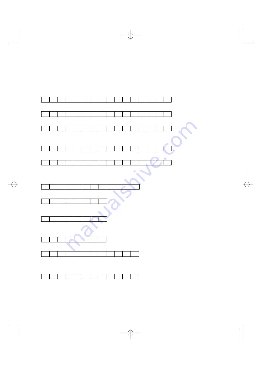
Typical examples of communication are shown as follows. (The station address are made 12.)

(1)  Standard frame

[1]  S05: Selecting frequency command (writing)

Request frame (host 

 inverter) ............... 40.00 Hz command

SOH

1

2

ENQ W

S

0

5

SP

0

F

A

0

ETX

8

1

ACK response frame (inverter 

 host)

SOH

1

2

ACK W

S

0

5

SP

0

F

A

0

ETX

8

2

NAK response frame (inverter 

 host) ..... Priority of link error

SOH

1

2

NAK W

S

0

5

SP

0

0

4

C

ETX

8

1

[2]  M09: Polling output frequency (reading)

Request frame (host 

 inverter)

SOH

1

2

ENQ

R

M

0

9

SP

0

0

0

0

ETX

5

3

ACK response frame (inverter 

 host) ..... 30.00Hz

SOH

1

2

ACK

R

M

0

9

SP

0

B

B

8

ETX

8

0

(2)  Option frame

[1]  Selection operation command (writing)

Request frame (host 

 inverter) ............... FWD command

SOH

1

2

ENQ

f

0

0

0

1

ETX

9

2

ACK response frame (inverter 

 host)

SOH

1

2

ACK

f

ETX

D

2

NAK response frame (inverter 

 host) ..... Cause of error can be confirmed with 

"M26: Transmission abnormal treatment code"

SOH

1

2

NAK

f

ETX

E

1

[2] Polling actual torque value (reading)

Request frame (host 

 inverter)

SOH

1

2

ENQ

h

ETX

D

3

ACK response frame (inverter 

 host) ..... 85.00%

SOH

1

2

ACK

h

2

1

3

4

ETX

9

E

[3] Selecting operation command in broadcast (writing)

The response is not returned in broadcast,

Request frame (host 

 inverter) ............... REV command

SOH

9

9

ENQ

f

0

0

0

2

ETX

A

2

Chapter02J(P44˜74).p65

07.8.9, 12:26

Page 56

Adobe PageMaker 6.5J/PPC

Summary of Contents for FRENIC5000G11S Series

Page 1: ......

Page 2: ......

Page 3: ...ls 1 37 4 2 1 Terminal block arrangement 1 37 4 2 2 Main circuit terminal 1 38 4 2 3 Control circuit terminal 1 41 Chapter 2 Operation 1 Frequency Control Operation 2 2 1 1 Types of frequency control...

Page 4: ...2 Time of receiving preparation completion 2 71 4 9 Function 2 71 4 10 Troubleshooting 2 72 4 11 Appendix 2 73 4 11 1 Communication level converter 2 73 4 11 2 ASCII code list 2 73 4 11 3 Example of...

Page 5: ...ional control cards 5 2 1 2 Other exclusive options 5 2 1 3 Datailed specifications 5 3 2 Optional Peripheral Equipment 5 14 2 1 Optional peripheral equipment 5 14 2 2 Specifications and dimensions 5...

Page 6: ...ndix 2 Effect on Insulation of General purpose Motor Driven with 460V Class Inverter 8 11 2 1 Operating principle of inverter 8 11 2 1 1 Main circuit configuration of inverter 8 11 2 1 2 Control metho...

Page 7: ...fications 1 6 2 1 Outline of common specifications 1 6 2 2 Protective functions 1 10 2 3 Function settings 1 11 3 Wiring Diagram 1 19 3 1 Wiring diagram before shipment from factory 1 19 3 2 Basic wir...

Page 8: ...le torque load 9 1 0 to 1 9 Manual for propotional speed torque load 2 0 to 20 0 Manual for constant torque load Starting torque 200 with Dynamic torque vector control selected 180 with Dynamic torque...

Page 9: ...load 10 1 0 to 1 9 Manual for propotional speed torque load 2 0 to 20 0 Manual for constant torque load Starting torque 200 with Dynamic torque vector control selected 180 with Dynamic torque vector c...

Page 10: ...9 1 0 to 1 9 Manual for propotional speed torque load 2 0 to 20 0 Manual for constant torque load Starting torque 50 Braking torque 10 20 10 to 15 Standard Time s No limit Duty cycle ED No limit Stan...

Page 11: ...iable torque load 10 1 0 to 1 9 Manual for propotional speed torque load 2 0 to 20 0 Manual for constant torque load Starting torque 50 Braking torque 11 20 10 to 15 Standard Time s No limit Duty cycl...

Page 12: ...FUJI private link Profibus DP Interbus S Modbus Plus Devicenet Programmed PATTERN operation Max 7 stages This operation can be performed by KEYPAD opration FWD REV key or digital input signal FWD or R...

Page 13: ...inal 12 0 to 10Vdc 0 to 100 Reversible operation with polarity terminal 12 V1 0 to 10Vdc 0 to 100 Inverse mode operation terminal 12 and V2 10 to 0Vdc 0 to 100 Inverse mode operation terminal C1 20 to...

Page 14: ...on method The inverter trips and then protects the motor Electronic thermal overload relay can be selected for standard motor or inverter motor The second motor s electronic thermal overload relay can...

Page 15: ...g value Tester function I O check Displays on off status of digital input and output signals level of analog input and pulse output signals Digital I O ON OFF Analog I O V mA H p s Maintenance data Op...

Page 16: ...e inverter When the built in or external braking resistor overheats the inverter stops discharging and running Function data appropriate for the resistor type built in external must be set G11S 10HP o...

Page 17: ...1 F03 MAX Hz 1 G11S 50 to 400Hz P11S 50 to 120Hz F04 Base frequency 1 F04 BASE Hz 1 G11S 25 to 400Hz P11S 25 to 120Hz F05 Rated voltage 1 F05 RATED V 1 0V The output voltage in proportion to the power...

Page 18: ...atic deceleration control 20 to 200 999 999 No limit 2 P11S 0 Automatic deceleration control 20 to 150 999 999 No limit F42 Torque vector control 1 F42 TRQVECTOR1 0 Inactive 1 Active Sets the frequenc...

Page 19: ...2 Frequency level detection FDT1 3 Undervoltage detection signal LU 4 Torque polarity B D 5 Torque limiting TL 6 Auto restarting IPF 7 Overload early warning OL1 8 KEYPAD operation mode KP 9 Inverter...

Page 20: ...el E31 FDT1 LEVEL G11S 0 to 400 Hz P11S 0 to 120 Hz E32 signal Hysteresis E32 FDT HYSTR 0 0 to 30 0 Hz E33 OL1 function Mode select E33 OL1 WARNING 0 Thermal calculation signal 1 Output current E34 Le...

Page 21: ...renced here may not be obtainable when P02 or A09 is set at 0 Motor Parameters Function Setting range Unit Min Factory setting Remarks Code Name LCD monitor unit 30HP 40HP P01 Number of motor 1 poles...

Page 22: ...H21 Feedback signal H21 FB SIGNAL 0 Terminal 12 0 to 10V 1 Terminal C1 4 to 20mA 2 Terminal 12 10 to 0V 3 Terminal C1 20 to 4mA H22 P gain H22 P GAIN 0 01 to 10 00 H23 I gain H23 I GAIN 0 0 Inactive...

Page 23: ...nce Cable X Cable resctance Primary conversion value V Rated voltage V I Motor rated current A Sets the slip frequency Function Setting range Unit Min Factory setting Remarks Code Name LCD monitor uni...

Page 24: ...l selection U56 Speed agreement Detection width U57 PG error Detection timer U58 PG error selection U59 Braking resistor function select up to 30HP Manufacturer s function 40HP or more U60 Regeneratio...

Page 25: ...60Hz or 3 phase 400 to 480V 50 60Hz Main circuit Grounding 4 Control circuit Analog input Potentiometer power supply Voltage input Current input Analog output analog monitor Digital input Pulse output...

Page 26: ...ltage input Current input Analog output analog monitor Digital input Pulse output frequency monitor RS 485 Pulse output Motor Alarm output for any fault Transistor output DB Relay output 3 Terminals P...

Page 27: ...og input Potentiometer power supply Voltage input Current input Analog output analog monitor Digital input Pulse output frequency monitor RS 485 Pulse output Motor Alarm output for any fault Transisto...

Page 28: ...log output analog monitor Digital input Pulse output frequency monitor RS 485 Pulse output Motor Alarm output for any fault Transistor output Relay output 3 Terminals P1 and P are connected with a jum...

Page 29: ...tal input Pulse output frequency monitor RS 485 Pulse output Motor Alarm output for any fault Transistor output Relay output 2 Use this peripheral device when necessary 1 Use the inverter whose rated...

Page 30: ...for any fault Transistor output DB Relay output 2 Use this optional device when necessary 1 Use the inverter whose rated input voltage matches the power supply voltage Jumper wire 4 NOTE Common termi...

Page 31: ...onal device when necessary 1 Use the inverter whose rated input voltage matches the power supply voltage Jumper wire 4 6 R0 T0 NOTE Common terminals 11 CM and CME for control circuits are isolated fro...

Page 32: ...r output Relay output 2 Use this optional device when necessary 1 Use the inverter whose rated input voltage matches the power supply voltage Jumper wire 4 R0 T0 NOTE Common terminals 11 CM and CME fo...

Page 33: ...the inverter whose rated input voltage matches the power supply voltage Jumper wire 4 R0 T0 NOTE Common terminals 11 CM and CME for control circuits are isolated from one another SR 3 2 1 60Hz pulse c...

Page 34: ...uits are isolated from one another SR 3 2 1 60Hz pulse counter 2 Digital frequency meter FM 2 0 to 60Hz Analog frequency meter 4 to 20mAdc Current input It is possible to input voltage signals 0 to 10...

Page 35: ...olated from one another SR 3 2 1 60Hz pulse counter 2 Digital frequency meter FM 2 0 to 60Hz Analog frequency meter 4 to 20mAdc Current input It is possible to input voltage signals 0 to 10Vdc or 0 to...

Page 36: ...nter 2 Digital frequency meter FM 2 0 to 60Hz Analog frequency meter 4 to 20mAdc Current input It is possible to input voltage signals 0 to 10Vdc or 0 to 5Vdc to terminals 12 11 instead of the potenti...

Page 37: ...2 1 60Hz pulse counter 2 Digital frequency meter FM 2 0 to 60Hz Analog frequency meter 4 to 20mAdc Current input It is possible to input voltage signals 0 to 10Vdc or 0 to 5Vdc to terminals 12 11 inst...

Page 38: ...ometer power supply 2 Analog input DC REACTOR DCR 2 4 DB P P DB P G G 2 1 2 1 N CM THR Braking unit BU 2 6 External braking resistor DB 2 5 73 7 Even if these terminals are not powered the inverter ca...

Page 39: ...d by function setting or digital input signal 20 to 4mA DC 0 to 100 Used for PID control reference signal or feedback signal The PTC thermisor for motor protection can be connnected to terminal 13 C1...

Page 40: ...ing by KEYPAD or is effective IVS ON Inverse mode is effective in analog signal input When a switch is connected between inverter and motor connect its auxiliary NC contact to this terminal When a mom...

Page 41: ...ge voltage is proportional to selected function s value 2670p s pulse width control Output frequency 1 Before slip compensation 0 to max frequency Output frequency 2 After slip compensation 0 to max f...

Page 42: ...al by FRENIC5000G9S series 40HP or larger Outputs time up signal 100ms ON pulse at every stage end of PATTERN operation Outputs one cycle completion signal 100ms ON pulse at PATTERN operation Outputs...

Page 43: ...1S 4UX FRN030P11S 4UX 40 FRN040G11S 4UX FRN040P11S 4UX 50 FRN050G11S 4UX 3 FRN050P11S 4UX 60 FRN060G11S 4UX FRN060P11S 4UX 3 75 FRN075G11S 4UX FRN075P11S 4UX Fig 7 100 FRN100G11S 4UX FRN100P11S 4UX 12...

Page 44: ...11S 2UX FRN075P11S 2UX 100 FRN100G11S 2UX 6 11 FRN100P11S 2UX 125 FRN125G11S 2UX 7 11 FRN125P11S 2UX 6 11 150 FRN150P11S 2UX 7 11 4 2 2 Main circuit terminal Main circuit terminal arrangement a Three...

Page 45: ...060P11S 4UX 75 FRN075G11S 4UX 5 11 FRN075P11S 4UX 5 11 100 FRN100G11S 4UX FRN100P11S 4UX 125 FRN125G11S 4UX FRN125P11S 4UX 150 FRN150G11S 4UX FRN150P11S 4UX 200 FRN200G11S 4UX FRN200P11S 4UX 250 FRN25...

Page 46: ...M12 M12 M10 M4 FRN100P11S 2UX 125 FRN125G11S 2UX FRN125P11S 2UX M12 M12 M10 M4 150 FRN150P11S 2UX 1 2 FRNF50G11S 4UX M3 5 M3 5 M3 5 M3 5 1 FRN001G11S 4UX 2 FRN002G11S 4UX 3 FRN003G11S 4UX M4 M4 M4 M4...

Page 47: ...30 FRN030G11S 2UX FRN030P11S 2UX FRN030G11S 4UX FRN030P11S 4UX 40 FRN040G11S 2UX FRN040P11S 2UX FRN040G11S 4UX FRN040P11S 4UX 50 FRN050G11S 2UX FRN050P11S 2UX FRN050G11S 4UX FRN050P11S 4UX 60 FRN060G...

Page 48: ...1 42 Chapter 1 4 Terminal Terminal size M2 5 Common for all models Chapter01J P33 42 p65 07 8 9 11 54 Page 42 Adobe PageMaker 6 5J PPC...

Page 49: ...unication 2 56 4 4 5 Communication error 2 57 4 5 Functions specific for communication 2 61 4 5 1 Command data 2 61 4 5 2 Operation command data 2 61 4 5 3 Function data 2 62 4 5 4 Monitoring data 2 6...

Page 50: ...vert the polarity of the DC voltage signal in addition to the control of item 3 above to change the rotating direction Input a 10 to 0Vdc voltage signal between the terminals 12 and 11 or V2 and 11 to...

Page 51: ...ted 15 RS 485 communication 16 PID control 17 T link 18 LINK operation Frequency setting can be made by means of communication with RS 485 as standard Optimum control is enabled by controlling feedbac...

Page 52: ...m key Switches the display to a menu screen or to the initial screen for operation mode or alarm mode Shift key Column shift In program mode Moves the cursor horizontally at data change Pressing this...

Page 53: ...FUNC SHIFT key to move the cursor when you want to enter a numerical value t Press the FUNC DATA key to store the updated function data in memory The screen shifts for the selection of the next funct...

Page 54: ...mand 6 Inverse mode operation terminal 12 10 to 0Vdc 7 Inverse mode operation terminal C1 20 to 4mA 8 Setting by UP DOWN control mode 1 initial value 0 terminals UP and DOWN E01 to E09 9 Setting by UP...

Page 55: ...Gain Bias C1 Inverse operation Inverse operation Option Normal inverse operation Gain Bias frequency Negative polarity prevention 1 2 3 6 7 8 9 10 11 PID control Operation selection Proportional Integ...

Page 56: ...0V 80 to 240V 460V 320 to 480V F03 MAX Hz 1 F07 Acceleration time 1 F08 Deceleration time 1 This function sets the acceleration time for the output fre quency from startup to maximum frequency and the...

Page 57: ...the characteristics of the driven motor F10 Electronic thermal O L relay for motor 1 Select F11 Electronic thermal O L relay Level F12 Electronic thermal O L relay Thermal time constant The electronic...

Page 58: ...f undervoltage is detected operation automatically restarts with the frequency at that time Operation is automatically restarted with the frequency at power failure Operation is automatically restarte...

Page 59: ...peration continuation level Time ON ON H15 Operation continuation level Set value 1 Set value 4 DC link circuit voltage Output frequency LV trip DC link circuit voltage Output frequency motor speed LV...

Page 60: ...sets the upper and lower limits for the setting frequency Set values G11S 0 to 400Hz P11S 0 to 120Hz The inverter output starts with the starting frequency when operation begins and stops with the st...

Page 61: ...n the timer value This function sets the frequency at stop Set values 0 1 to 6 0Hz The operation does not start when the starting frequency is less than the stop frequency or when the setting frequenc...

Page 62: ...pulse frequency of the monitor item selected in F35 within a range of 300 to 6000p s in 1 p s steps Set values 300 to 6000 p s Pulse frequency p s 1 T Duty T1 T x 100 Average voltage V 15 6 x T1 T Thi...

Page 63: ...rol difficult 2 The function data P03 Rated current P06 No load current P07 R1 setting and P08 X setting of motor 1 must be correct When the FUJI standard 3 phase motor is used setting the capacity fu...

Page 64: ...ion 4 5 This function is used for 3 wire operation The FWD or REV signal is self held when HLD is on and the self hold is cleared when HLD is turned off To use this HLD terminal function assign value...

Page 65: ...ting them clears trip indication and restarts operation To use this RST terminal function assign value 8 to the target digital input terminal Disconnecting THR and CM during operation cuts off inverte...

Page 66: ...19 PID control cancel Hz PID 20 Interlock signal 52 2 IL 22 There are the two types of UP DOWN operations as shown below Set the desired type by setting the frequency com mand F01 or C30 Combination o...

Page 67: ...PID control operation is selected H20 1 or 2 H18 Link enable RS 485 standard Bus option LE 24 Set value input signal Function selected 24 off Link command invalid on Link command valid Pick up start m...

Page 68: ...t a signal to each terminal to switch acceleration and deceleration times Switching is possible during acceleration deceleration or constant speed operation Example When 4 and 5 are set to terminals X...

Page 69: ...tion signal Level NOTE This function is effective for motor 1 only An ON signal is output when operation command keys FWD REV and STOP keys on the KEYPAD panel can be used i e 0 set in F02 Operation m...

Page 70: ...ation forward or reverse command is entered this function outputs an ON signal When a stop command is entered the signal goes off after inverter output stops When a coast to stop command is entered an...

Page 71: ...set frequency operating frequency The detection width can be adjusted from 0 to 10 Hz of the setting frequency E30 Setting range 0 0 to 10 0 Hz When the frequency is within the detection width an ON s...

Page 72: ...n and thermal time constant for the inverse time characteristics are the same as those of the electronic thermal O L relay for motor protection F10 and F12 An overload early warning is issued when out...

Page 73: ...Contrast This function adjusts the LCD contrast Increase the set value to raise contrast and decrease to lower contrast Value set to E43 Frequency setting 0 1 2 3 4 Set frequency value Hz 5 Synchronou...

Page 74: ...Output frequency Hz Output frequency Hz Jump frequency width Jump frequency width Jump frequency width Jump frequency width Jump frequency 3 Jump frequency 2 Jump frequency 2 Jump frequency 1 Jump fr...

Page 75: ...ON SS8 CM SS4 CM SS2 CM SS1 CM FWD CM ON ON ON ON ON ON ON Output frequency Hz C20 JOG Hz C21 PATTERN FWD FWD FWD 0 0 0 Set value 0 End of a cycle Time Forward Reverse Output frequency Set value 1 En...

Page 76: ...ses stage advance Pressing the FWD key again restarts operation from the stop point according to the stages If an alarm stop occurs press the RESET key to release operation of the inverter protective...

Page 77: ...tting frequency is determined by adding inputs to terminals 12 and V1 Polarized input allows operation in the direction opposite that of an operation command 6 Inverse mode operation terminal 12 10 to...

Page 78: ...to 5 00s A set value too large delays control response though stabiliz ing control A set value too small speeds up control response but renders control unstable If the optimum value is unknown change...

Page 79: ...rol When output side impedance cannot be ignored as when cable between the inverter and the motor is too long or when a reactor is connected When R1 or X is unknown as when a non standard or special m...

Page 80: ...eakage reactance converted to a primary value of the motor XM Exciting reactance of motor Cable X Output side cable reactance V Rated voltage V I Motor rated current A NOTE For reactance use a value b...

Page 81: ...05 Auto reset Reset interval This operation is re peated until the cause of the alarm is removed The restart operation switches to alarm mode when the retry count exceeds the value set in H04 Auto res...

Page 82: ...6 Pick up start mode to terminals X1 to X9 this function can be externally selected as the normal startup method when an ON operation command is entered Set value 0 ON OFF control disabled 1 ON OFF co...

Page 83: ...duced when instanta neous overcurrent limiting is applied set this function to be inactive for equipment such as elevators which are ad versely affected by reduced motor generation torque in which cas...

Page 84: ...tive A 0 to 10 V analog voltage input to terminal 12 and the direction of rotation FWD or REV is used for the torque command value 0 is used for 0 to 10V 2 Torque control active A 10 to 10V analog vol...

Page 85: ...k amount the process amount can be displayed according to the values set in E40 Feedback amount Reference value Drive section Control target P I D H20 PID MODE 0 100 0 PID output Inverter output frequ...

Page 86: ...operation amount output frequency is proportional to the deviation differential is called D opera tion which outputs an operation amount as the deviation differential and therefore is capable of respo...

Page 87: ...n the value of H23 I gain increase the value of H23 To suppress vibration with a frequency roughly equivalent to the value H24 D gain decrease the value of H24 If there is residual vibration with 0 0...

Page 88: ...re Alarm temperature H28 DROOP Speed When droop control is active Rated torque 0 When droop control is inactive Torque Synchronous speed H30 Serial link Function select The link function communication...

Page 89: ...ction set processing at communication error and sets the error processing timer value Setting range 0 to 3 Setting range 0 to 60 0s H34 RS 485 Baud rate This function sets the transmission speed Setti...

Page 90: ...maximum frequency for motor 2 output by the inverter This function operates the same as F03 Maximum frequency 1 For details see the explanation for F03 A02 Base frequency 2 This function sets the maxi...

Page 91: ...08 Motor 1 X setting For details see the explanations for P07 and P08 A18 Motor 2 Slip compensation control This function sets the amount of slip compensation for motor 2 This function operates the sa...

Page 92: ...ON Denotes operating procedures and practices that if not strictly observed may result in damage to or destruction of the equipment Warning Be sure to wire after power supply off There is a fear of el...

Page 93: ...and output voltage Operation state and universal output terminals Maintenance integrated operation time DC link circuit voltage internal air temperature in inverter and fin temperature All function da...

Page 94: ...ut terminal hot side TRD Differential output terminal common side FG Frame ground IN IN Differential input terminal OUT OUT Differential output terminal SD Signal ground FRENIC5000G11S Inverter 2 DXA...

Page 95: ...ers as broad cast By using broadcast operation commands and frequency command can be give all the inverters in a lump The writing of S01 S06 W E commands in the standard frame and a f and m commands i...

Page 96: ...1 Station address 0 3 9 30H 33H 39H Station address of inverter Decimal x 10 2 0 9 30H 39H Station address of inverter Decimal x 1 3 ENQ ENQ 05H Transmission request 4 Command Request command R 52H Po...

Page 97: ...type F 46H Fundamental Functions E 45H Extension Terminal Functions C 43H Control Functions of Frequency P 50H Motor Parameters H 48H High performance Functions A 41H Alternative Motor Parameters o 6...

Page 98: ...Type 1 Function type F 46H Fundamental Functions E 45H Extension Terminal Functions C 43H Control Functions of Frequency P 50H Motor Parameters H 48H High performance Functions A 41H Alternative Moto...

Page 99: ...ecimal x 100H 7 0 F 30H 3FH 3rd character of data Hexadecimal x 10H 8 0 F 30H 3FH 4th character of data Hexadecimal x 1H 9 ETX ETX 03H End of text 10 BCC 0 F 30H 3FH Check sum 1 Hexadecimal x 10H 11 0...

Page 100: ...0H 7 0 F 30H 3FH Check sum 2 Hexadecimal x 1H Byte Field Value Description ASCII type Hexadecimal 0 SOH SOH 01H Start of header 1 Station address 0 3 9 30H 33H 39H Station address of inverter Decimal...

Page 101: ...ided in addition to 4 bytes of the data field and minus is set only when communicating negative data exceeding 16 bits length output frequency of M09 and M35 in reverse rotation Notes Make all A F of...

Page 102: ...performed after this If this phenomena frequently occurs investigation is necessary since there is a possibility of any abnormality In a case of no response again retry further When the times of retr...

Page 103: ...es Cannot write during writing function data from link option Yes Send again with normal function code Yes Send again with normal range of data Yes Written into the function of forbidden writing expec...

Page 104: ...CK response frame inverter host 30 00Hz SOH 1 2 ACK R M 0 9 SP 0 B B 8 ETX 8 0 2 Option frame 1 Selection operation command writing Request frame host inverter FWD command SOH 1 2 ENQ f 0 0 0 1 ETX 9...

Page 105: ...rror 74 4AH Format error 75 4BH Command error 76 4CH Priority of link error 77 4DH Error of no writing right 78 4EH Function code error 79 4FH Error of forbidden writing 80 50H Data error 81 51H Error...

Page 106: ...set Coast to stop Stop Operation ON Operation ON Communication failure Er8 Normal Error Normal Normal Er8 Alarm reset In acceleration even if occurring transmission error accelerated to the setting fr...

Page 107: ...occurring transmission error accelerated to the setting frequency In a case of H32 2 H33 5 0s A communication error occurs but restored within 5s Normal Error Normal Stop Opration ON 1 5 0s OFF Inter...

Page 108: ...ommunication error 1 Increment conditions of transmission error counter When a frame for own station Communication error code 71 When a receiving error parity framing over run occurs Communication err...

Page 109: ...uency at 20000 S05 Setting frequency Hz 0 00 to 400 00 P11S 0 00 to 120 00 0 01 R W Code Name Unit Variable range Min unit Read write S06 Operation command Refer to the data format 14 R W S07 Universa...

Page 110: ...DI Universal DI 26 STM Pick up start mode Valid 27 PG Hz SY PG enable Valid Invalid 28 SYC Synchronization command 29 ZERO Zero speed command 30 STOP1 Forced stop command Invalid Valid 31 STOP2 Forced...

Page 111: ...the data format 11 R M25 ROM version 0 64999 1 R M26 Transmission error code Refer to the data format 10 R M27 Setting frequency at alarming Final data 20000 to 20000 Maximum frequency at 20000 1 R M...

Page 112: ...31 FMA terminal Function selection 1 F33 FMP terminal Pulse rate multiplier 1 F34 FMP terminal Voltage adjust 1 F35 FMP terminal Function selection 1 F36 30Ry operation mode 1 F40 Torque limit 1 Drivi...

Page 113: ...H06 Fan stop operation 1 H07 ACC DEC pattern Mode selection 1 H08 Reverse phase sequence lock 1 H09 Start mode Pick up mode 1 H10 Energy saving operation 1 H11 Deceleration mode 1 H12 Instantaneous ov...

Page 114: ...S08 Acceleration time 3 S09 Deceleration time 3 S10 Torque limit level 1 5 1 S11 Torque limit level 1 5 1 S12 Universal Ao 2 M01 Setting frequency Final data 2 M05 Setting frequency Final data 5 M06 O...

Page 115: ...9 Integer data Positive Min unit 2 Example If P01 Motor 1 number of poles 2 poles Since 2 0002H 0 0 0 2 Data format 10 Alarm code Example If overvoltage during acceleration OU1 Since 6 0006H 0 0 0 6...

Page 116: ...ion Not used Time 0 0 01 X 000 999 0 00 9 99 1 0 1 X 100 999 10 0 99 9 2 1 X 100 999 100 999 3 10 X 100 999 1000 9990 0 Forward rotation 1 Reverse rotation 0 ACC DEC time 1 1 ACC DEC time 2 2 ACC DEC...

Page 117: ...writing of function data and functions are possible in any time regardless the communication valid or invalid Data format 19 Polarity decimal positive Min unit 0 01 Example If M09 Output frequency 60...

Page 118: ...ry Response Query t1 t2 t1 t2 Inverter Host Broadcast Broadcast Broadcast 4 8 1 Response interval time The time till start of response sending after receiving a query from the host such as PLC and PC...

Page 119: ...f the setting value When option related to busses is provided this setting in the function becomes the function selecting of the option and the function of RS 485 is restricted only to monitoring and...

Page 120: ...e converter When using RS 232C is using method of the communication level converter is correct Review the connection method and check connection of the terminating resistor and cable Is the wiring cor...

Page 121: ...ing the sending data on the host RS 232C side Isolation The device shall be electrically isolated from RS 485 Fail safe With fail safe function Others Excellent noise proof characteristics 4 11 2 ASCI...

Page 122: ...z 3010 CMD SOH SOH 3020 CMD CMD 01 ADDRESS 01 31 3030 CMD CMD ENQ ENQ 3040 CMD CMD W COMMAND R W A E 3050 CMD CMD F03 CODE F00 3060 CMD CMD 0032 DATA 0000 FFFF 3070 CMD CMD ETX ETX 3080 4000 SEND 4010...

Page 123: ...ation of each part having lifetime on the KEYPAD panel A warning signal can be output when the conditions of each part having life become under the standard lives The capacitance of the capacitor is m...

Page 124: ...he main circuit capacitor it is shown as the life accumulation time that the supplied time of the control power supply is multiplied by life coefficient depending on the ambient temperature of the PC...

Page 125: ...ng Resistor 3 10 5 Braking Unit and Braking Resistor 10 ED 3 12 6 Rated Sensitive Current of GFCI 3 14 7 Input Circuit Noise Filter EMC Compliance Filter 3 15 8 Output Circuit Noise Filter OFL 2 4 3 1...

Page 126: ...ed for following condi tions 30HP or smaller Power source capacity 500kVA Power source impedance 2 5 40HP or larger Power source capacity and impedance are calculated using values corresponding to Fuj...

Page 127: ...005G11S 4UX 10 20 7 5 FRN007G11S 4UX FRN007P11S 4UX 15 30 SC 4 0 SC 05 10 FRN010G11S 4UX FRN010P11S 4UX 20 40 SC 5 1 15 FRN015G11S 4UX FRN015P11S 4UX 30 50 SC N1 SC 4 0 SC 4 0 20 FRN020G11S 4UX FRN020...

Page 128: ...4UX 2 9 2 0 2 0 6 2 2 0 3 7 3 FRN003G11S 4UX 2 0 2 0 4 2 2 0 9 2 2 0 5 5 5 FRN005G11S 4UX 2 0 7 1 14 9 2 0 9 7 5 FRN007G11S 4UX FRN007P11S 4UX 10 5 5 21 5 13 10 FRN010G11S 4UX FRN010P11S 4UX 13 5 5 5...

Page 129: ...5 5 3 5 37 100 100 150 150 150 346 200 150 400 22 14 8 0 61 14 8 0 5 5 48 150 100 200 150 415 250 200 490 22 14 8 0 61 200 150 1 0 0 8 1 8 1 1 2 0 3 6 1 8 2 0 2 0 5 1 1 8 2 0 2 0 8 7 2 1 2 0 2 0 12 5...

Page 130: ...75P11S 2UX 100 60 38 199 100 100 291 100 60 60 215 100 FRN100P11S 2UX 100 60 272 150 100 100 283 FRN100G11S 2UX 150 125 FRN125G11S 2UX FRN125P11S 2UX 200 150 100 327 200 150 100 346 150 FRN150P11S 2UX...

Page 131: ...0 150 150 100 346 150 150 400 14 8 0 5 5 61 8 0 5 5 5 5 48 200 150 100 150 150 415 200 150 490 14 8 0 5 5 61 250 150 150 1 0 0 8 1 8 1 1 2 0 3 6 1 8 2 0 2 0 5 1 1 8 2 0 2 0 8 7 2 1 2 0 2 0 12 5 12 3 2...

Page 132: ...88 866 812 758 682 2 x 400 1515 1428 1341 1242 1130 1018 993 931 869 782 2 x 500 1711 1613 1515 1403 1276 1150 1122 1052 982 883 HIV wire Maximum allowable temperature 75 C 167 F Allowable current Wir...

Page 133: ...62 155 148 140 132 124 108 103 97 92 38 228 218 208 197 186 174 152 145 137 129 60 305 292 279 264 249 234 203 195 184 173 100 420 402 384 363 342 321 280 268 253 238 150 556 533 509 481 454 426 371 3...

Page 134: ...U55 2C 1 DB45 2C 1 2 5 100 2584 292 2151 243 225 10 2 25 10 FRN075G11S 2UX 1 DB55 2C 1 2 0 3177 359 2638 298 275 10 2 75 10 FRN100G11S 2UX BU90 2C 1 DB75 2C 1 1 5 4310 487 3585 405 375 10 3 75 10 FRN1...

Page 135: ...Aver age loss kW Duty cycle Cont braking 100 torque conversion value Repetitive braking 100s or less cycle Option Maximum braking torque Power Braking unit Braking resistor supply Inverter type voltag...

Page 136: ...220 2 1 DB11 2C 1 10 868 98 1 720 81 4 55 7 0 55 10 FRN025P11S 2UX 1 DB15 2C 1 8 6 1071 121 885 100 75 7 0 75 7 FRN030P11S 2UX BU37 2C 1 DB22 2C 5 8 1275 144 1053 119 93 7 0 925 7 Total ohmic value D...

Page 137: ...ons inch mm DB0 75 4C DB2 2 4C DB3 7 4C DB5 5 4C DB7 5 4C DB11 4C DB15 4C DB22 4C DB0 75 2C DB2 2 2C DB3 7 2C DB5 5 2C DB7 5 2C DB11 2C DB15 2C DB22 2C A B C D 1 69 43 2 64 67 3 15 80 7 09 180 W 230V...

Page 138: ...150 FRN150P11S 2UX 383 1 2 FRNF50G11S 4UX 1 2 1 FRN001G11S 4UX 1 8 2 FRN002G11S 4UX 3 3 3 FRN003G11S 4UX 4 6 5 FRN005G11S 4UX 7 5 30mA 7 5 FRN007G11S 4UX FRN007P11S 4UX 11 10 FRN010G11S 4UX FRN010P11S...

Page 139: ...03G11S 4UX FRN005G11S 4UX FRN007G11S 4UX FRN010G11S 4UX FRN015G11S 4UX FRN020G11S 4UX FRN025G11S 4UX FRN030G11S 4UX FRN040G11S 4UX FRN050G11S 4UX FRN060G11S 4UX FRN075G11S 4UX FRN100G11S 4UX FRN125G11...

Page 140: ...UX OFL 22 4 45 380 to 95 43 30 FRN030G11S 4UX FRN030P11S 4UX 460V 40 FRN040G11S 4UX FRN040P11S 4UX OFL 30 4 60 50 60Hz 84 38 50 FRN050G11S 4UX FRN050P11S 4UX OFL 37 4 75 101 46 60 FRN060G11S 4UX FRN06...

Page 141: ...255 10 63 270 11 81 300 12 40 315 13 19 335 12 80 325 13 58 345 14 17 360 6 30 160 6 69 170 7 09 180 7 48 190 5 91 150 6 69 170 7 09 180 7 48 190 7 87 200 8 27 210 9 06 230 9 45 240 Earth terminal M4...

Page 142: ...FRN060G11S 4UX FRN060P11S 4UX OFL 45 4A 91 75 FRN075G11S 4UX FRN075P11S 4UX OFL 55 4A 112 50 60HZ 100 FRN100G11S 4UX FRN100P11S 4UX OFL 75 4A 150 150 125 FRN125G11S 4UX FRN125P11S 4UX OFL 90 4A 176 1...

Page 143: ...40 13 78 350 6 89 175 8 86 225 11 42 290 10 83 275 11 81 300 6 89 175 7 48 190 7 68 195 7 87 200 8 27 210 9 06 230 9 45 240 10 63 270 11 81 300 7 68 195 8 66 220 9 06 230 12 20 310 12 99 330 8 27 210...

Page 144: ...25 FRN125G11S 2UX FRN125P11S 2UX DCR2 90B 410 0 067 57 150 FRN150P11S 2UX DCR2 110B 526 0 055 67 1 2 FRNF50G11S 4UX DCR4 0 4 1 5 50 1 5 1 FRN001G11S 4UX DCR4 0 75 2 5 30 2 1 2 FRN002G11S 4UX DCR4 1 5...

Page 145: ...S 2UX FRN075P11S 2UX 66 1 100 FRN100G11S 2UX FRN100P11S 2UX ACR2 75 390 5 45 6 54 0 250 55 1 125 FRN125G11S 2UX FRN125P11S 2UX ACR2 90 450 4 73 5 67 0 198 61 5 150 FRN150P11S 2UX ACR2 110 500 4 25 5 1...

Page 146: ...0 5 43 138 7 87 200 0 39x0 79 10x20 10 63 270 66 30 ACR4 0 75A 4 72 120 2 56 65 3 54 90 2 4 1 1 ACR4 1 5A M4 4 2 1 9 ACR4 2 2A 4 92 125 1 57 40 2 95 75 3 94 100 0 24x0 39 3 74 95 4 9 2 2 ACR4 3 7A 6x1...

Page 147: ...oltage V 340 Rated current A 25 50 74 120 182 Input Overload capability 150 for 1min ratings Phases Voltage Frequency Three phase 200 220V 50 60Hz Voltage frequency variations Voltage 10 to 15 Voltage...

Page 148: ...by electronic thermal function and detection of temperature inside OL Overheating Stops operation of the unit by detecting heat sink overheating OH AC fuse blown Stops operation of the unit by detecti...

Page 149: ...or over For F08 F09 F10 see next page Common for transistor output signal Outputs ON signal when the converter is ready for operation Initial charge and voltage step up completed Outputs a contact sig...

Page 150: ...immediately when it detects excess heat sink temperature or an abnormal rise in temperature inside the converter OH Power supply abnormal frequency Stops the converter operation immediately when the...

Page 151: ...y is not exceeded FRN007P11S 2UX FRN010P11S 2UX FRN015P11S 2UX FRN020P11S 2UX FRN025P11S 2UX FRN030P11S 2UX FRN040P11S 2UX FRN050P11S 2UX FRN060P11S 2UX FRN075P11S 2UX FRN100P11S 2UX FRN125P11S 2UX FR...

Page 152: ...1100 14 88 378 23 43 595 28 74 730 14 88 378 20 87 530 25 79 655 31 89 810 42 13 1070 42 52 1080 7 44 189 10 83 275 11 02 280 7 44 189 10 43 265 10 83 275 10 63 270 12 40 315 14 17 360 3 68 93 5 6 69...

Page 153: ...LFC2 55 LFC4 37 LFC4 55 LFC4 75 LFC4 110 LFC4 160 LFC4 220 10 04 255 10 04 255 12 60 320 13 78 350 14 57 370 6 69 170 6 69 170 4 13 105 4 53 115 4 72 120 7 68 195 7 68 195 11 61 295 12 60 320 14 57 37...

Page 154: ...3 30 3 12 13 P23 30 65p 07 8 9 12 34 Page 30 Adobe PageMaker 6 5J PPC...

Page 155: ...orque during constant speed running 4 6 1 3 2 Acceleration and deceleration time calculation 4 7 1 3 3 Heat energy calculation of braking resistor 4 9 1 3 4 Appendix calculation for other than in SI U...

Page 156: ...orque obtained by using the inverter FRENIC5000G11S P11S Motor output torque characteristics See Section 1 1 Torque characteristics continuous output torque output torque in a short time braking torqu...

Page 157: ...onverted to electrical energy and regenerated to the smoothing capacitor in the inverter A Iarge braking torque as shown in curve e can be obtained by discharging this electrical energy to the braking...

Page 158: ...unit of higher rating Is the loss permissible Regenerative energy calculation Deceleration time too long Deceleration time calculation Add optional braking resistor braking unit Deceleration time too...

Page 159: ...heck the motor deceleration torque characteristics for the whole range of speed in the same way as for the acceleration time q q q q q Calculate moment of inertia for the load and motor Same as for ac...

Page 160: ...r min 1 3 Selection calculation expressions 1 3 1 Load torque during constant speed running 1 General expression The frictional force acting on a horizontally moved load must be calculated For loads l...

Page 161: ...In this way the mechanical moment of inertia is an important element in acceleration and deceleration First calculation method of moment of inertia is described then that for acceleration and decelera...

Page 162: ...metal density at 20 C kg m3 Iron 7860 Copper 8940 Aluminum 2700 w w w w w For a general rotating body Table 4 1 lists the calculation expressions of moment of inertia of various rotating bodies inclu...

Page 163: ...ficiency In the above expression generally output torque M is negative and load torque L is positive So deceleration time becomes shorter However in a lifted and lowered load L may become a negative v...

Page 164: ...2 1 kg cm2 98000 Pa 980 mbar 1 atmospheric pressure 1013 mbar 760 mmHg 101300 Pa 1 033 kg cm2 2 Calculation formula 1 Torque power and rotation speed 2 P W 60 N r min N m P W 1 026 N r min T kgf m P W...

Page 165: ...istor 3 Average loss obtained by dividing discharge energy by cyclic period must not exceed average loss kW listed in the Tables 3 1 and 3 2 in Chapter 3 2 2 Notes on Selection The P11S series uses on...

Page 166: ...4 12...

Page 167: ...ntrol cards 5 2 1 2 Other exclusive options 5 2 1 3 Datailed specifications 5 3 2 Optional Peripheral Equipment 5 14 2 1 Optional peripheral equipment 5 14 2 2 Specifications and dimensions 5 15 Chapt...

Page 168: ...IP20 enclosure adapter P20G11 Mounting adapter for external cooling PBG11 Panel mount adapter MAG9 Name Type Function Auxiliary input for analog frequency setting 0 to 10V 4 to 20mA Analog monitoring...

Page 169: ...code o22 Output Analog signal output 2 points by short circuiting terminals between AO AO CS and CS Terminal AO Voltage output 0 to 10Vdc for max 2 voltmerters input impedance 10k Terminal AO Voltage...

Page 170: ...ircuiting terminals between O1 to O6 and M2 Sink ON operation current 50mA max OFF operation voltage 27V max Source ON operation current 50mA max OFF operation voltage 27V max Related function code o2...

Page 171: ...in use Name PG feedback card Applicable encoder generator Power source PI PO XA XB XZ CM PO YA YB YZ CM a 12Vdc b 15Vdc J1 J2 INT EXT 15V 12V J1 J2 INT EXT 15V 12V M PG L1 R L2 S L3 T U V W G FRENIC...

Page 172: ...card PG power input 5V Applicable pulse generator Power source Specifica tions YA YB CM Connect A and B phase output signal from pulse generator on feedback side YZ CM Connect Z phase output signal f...

Page 173: ...te of the power source matches the specifications of the applied pulse generator Connection diagram Remarks Terminals XA XB and XZ are not in use Name PG feedback card Frequency dividing output Applic...

Page 174: ...s limitation Use the equipment at ambient temperature 40 104 or below 2 Though the inverter rated output current is larger than the motor rated current There is no problem in use 3 The combination sho...

Page 175: ...e used for when inverter internal power source is used When using external power source perform connection similar to the above connection by referring to 2 When using external power supply of PG feed...

Page 176: ...rator Connect the pulse generator A phase B phase output signal None Internal power source 15Vdc 10 120mA 12Vdc 10 120mA Change able on PC board 1 External power source 12Vdc 10 to 15Vdc 10 300mA or l...

Page 177: ...G11S COP Setting of operation frequency Setting of operation command FWD REV RST etc Setting and reading out of function code and data code Monitoring of operating status Reading out of inverter trip...

Page 178: ...tion manual o27 o28 o29 None Connection diagram Remarks Name T link interface card Transmission specification Power source Specifica tions No of words used Relative function code MCCB or GFCI L1 R L2...

Page 179: ...0 06 1 6 0 13 3 2 3 35 85 1 2 36 59 9 6 54 166 Panel cutting Side view Option type Applicable inverter PBG11 0 75 FRNF25G11S 2UX to FRN001G11S 2UX FRNF50G11S 4UX A 1 37 34 9 FRN001G11S 4UX 1 97 49 9...

Page 180: ...4A This filter has the following functions q Suppressing fluctuation of motor terminal voltage Protects the motor insulation from being damaged by surge voltage 460V w Suppressing leakage current fro...

Page 181: ...0 98 25 1 38 35 1 61 41 FM 60 10V DC 1mA 0 94 0 01 24 0 2 0 94 0 01 24 0 2 0 94 0 01 24 0 2 0 94 0 01 24 0 2 Panel cutout 2 0 14 2 3 5 0 43 11 Mtg bolt 2 M3 Approx Mass 0 15lbs 70g Cover option Termi...

Page 182: ...3 12 13 P23 30 65p 07 8 9 12 34 Page 30 Adobe PageMaker 6 5J PPC 5 16...

Page 183: ...Circulation type Parking Facility 6 10 2 5 Using with Bread Dough Mixers 6 12 2 6 Using with Commercial use Washing Machines 6 14 2 7 Using with Belt Conveyors 6 16 2 8 Using with Grinding Machines 6...

Page 184: ...AR function signal function E20 to E24 FDT function signal E20 to E24 OL function signal Frequency F23 F24 Starting frequency control C01 to C04 Jump frequency C33 Frequency setting signal filter LED...

Page 185: ...istics A11 to A17 Motor 2 rating impedance Option for braking Motor protection Recommended inverter application G11S P11S Page for reference 6 24 6 4 6 16 6 6 6 14 6 40 6 16 6 30 6 8 6 30 6 34 6 10 6...

Page 186: ...ng operation is activated when the system has sufficient treatment capacity 3 Unnecessary to resort to any special sound proofing measures Fuji inverter drives a motor with silent motor sound We have...

Page 187: ...OR DCR to reduce harmonics on power supply side 6 Suppression of inrush current when the power supply is turned on FRENIC5000G11S series inverters have a built in circuit that suppresses inrush curren...

Page 188: ...e slip compensation control function can be set to main tain stable rotating speed even if the size of the load changes To improve the stopping accuracy the conveyance speed is first reduced then the...

Page 189: ...A17 X setting A18 Slip compensation control E07 X7 terminal Function select H06 Fan stop operation F26 Motor sound Carrier freq F14 Restart mode after momentary power failure Mode select 1 Active Stan...

Page 190: ...e inverter automatically determines the condition of the cars conveyed and adjusts the acceleration and deceleration times 3 Overcurrent tripping prevention with the torque limiting function When an a...

Page 191: ...ed current P04 Tuning P05 On line tuning P06 No load current P07 R1 setting P08 X setting P09 Slip compensation control A06 Electronic thermal relay for motor 2 Select A07 Level A08 Thermal time const...

Page 192: ...on and deceleration can be set to reduce the time required to convey cars in and out of the parking facility However in linear acceleration and deceleration acceleration and deceleration can quickly c...

Page 193: ...s turned on No measures have to be taken to handle inrush current in particular F10 Electronic thermal relay for motor 1 Select F11 Level F12 Thermal time constant F42 Torque vector control 1 P01 Moto...

Page 194: ...se in severe environ ments This inverter has a fully enclosed structure IP40 up to 30HP as standard Also available are a water proof structure IP65 up to 10HP and IP54 15 to 30HP as a separate series...

Page 195: ...supply is turned on FRENIC5000G11S series inverters have a built in circuit that suppresses inrush current that are generated when the power supply is turned on 7 Keypad panel designed with six forei...

Page 196: ...200 Dynamic torque vector control incorporating leading tech nologies enables a high starting torque of 200 at 0 5 Hz 4 Unnecessary to resort to any special sound proofing measures Fuji inverter drive...

Page 197: ...anish Italian and Japanese 2 Manufactured on request Chinese English and Japanese Function Name Factory setting Recommended setting value Remarks code E01 X1 terminal Function select E02 X2 terminal E...

Page 198: ...carrying amount varies the operating frequency can be easily changed using the multistep frequency function The carrying items can be transported smoothly without stopping the conveyor 4 Unnecessary...

Page 199: ...as standard Connect the optional DC REACTOR DCR to reduce harmonics on power supply side 5 Suppression of inrush current when the power supply is turned on FRENIC5000G11S series inverters have a buil...

Page 200: ...ting torque of 200 at 0 5 Hz 4 Unnecessary to resort to any special sound proofing measures Fuji inverter drives a motor with silent motor sound We have succeeded in eliminating most of the unpleasant...

Page 201: ...products English German French Spanish Italian and Japanese 2 Manufactured on request Chinese English and Japanese E01 X1 terminal Function select E02 X2 terminal E03 X3 terminal E04 X4 terminal E05...

Page 202: ...r conditioning system is significant Furthermore the cooling fan stop operation contributes to a more quiet operation as the cooling fan operation sound may be a nuisance at night 3 Unnecessary to res...

Page 203: ...DC REACTOR DCR to reduce harmonics on power supply side 6 Suppression of inrush current when the power supply is turned on FRENIC5000G11S P11S series inverters have a built in circuit that suppresses...

Page 204: ...ation command is off Although energy savings may appear minimal from the point of view of the air conditioning unit itself the total saving effect that can be realized by the whole air conditioning sy...

Page 205: ...rned on No measures have to be taken to handle inrush current in particular H20 PID control Mode select H21 Feedback signal H22 P gain H23 I gain H24 D gain H25 Feedback filter E01 X1 terminal Functio...

Page 206: ...when the flow is restricted by the valve significant energy savings can be expected Moreover you can anticipate greater energy savings by setting the automatic energy saving operation function Functio...

Page 207: ...in circuit that suppresses inrush current that are generated when the power supply is turned on F04 Base frequency 1 H20 PID control Mode select H21 Feedback signal H22 P gain H23 I gain H24 D gain H...

Page 208: ...es a motor with silent motor sound We have succeeded in eliminating most of the unpleasant motor sound that usually comes from the motor which is driven by the inverter The sound levels are comparable...

Page 209: ...use metal conduits for wiring and ground the control panel motor and conduits using lower resistance values 6 Full preparation to suppress harmonics with a DC REACTOR An exclusive terminal P1 P for c...

Page 210: ...R MC1 MC3 MC2 ZACL ACL THR DCR U V W P P1 AX Y5B Y5A 30 Inverter G11S P11S R S T R0 T0 12 X4 CM FWD X3 SW60 C1 Hz2 1 CP1 CP2 Control circuit 2 1 4 3 5 6 4 20mA 43 AUT FX FX T2 VR 43 M1 43 M3 43 M2 Loc...

Page 211: ...Switching operation between line and inverter 50Hz SW50 16 Switching operation between line and inverter 60Hz SW60 Set value Function 11 Line Inv changeover for 88 SW88 12 Line Inv changeover for 52...

Page 212: ...3 12 13 P23 30 65p 07 8 9 12 34 Page 30 Adobe PageMaker 6 5J PPC 6 30...

Page 213: ...7 7 1 Chapter 7 Glossary Contents 1 Standard Specifications 7 2 2 Common Specifications 7 4 Chapter7 1 P1 3 p65 07 8 9 12 48 Page 1 Adobe PageMaker 6 5J PPC...

Page 214: ...culated by solving either of the following equations and is stated in kVA Required power kVA 3 x 200 x Input rms current supply capacity 200V 50Hz or 3 x 220 x Input rms current 220V 60Hz Required pow...

Page 215: ...he motor works as a generator when it decelerates causing the kinetic energy of the load to be converted to electric energy that is returned to the inverter from the motor If this power regenerative p...

Page 216: ...p frequency selection To preset frequencies up to 16 stages then select them at some later time 12 bit parallel signals 12 bit binary A variation of inverter control signals T link Fuji Electric s exc...

Page 217: ...ntrol The scheme of control that brings controlled objects to a desired value quickly and accurately and which consists of three categories of action proportional integral and derivative Proportional...

Page 218: ...on H07 ACC DEC pattern in Sections 3 Chapter 2 S curve acceleration deceleration strong See Function H07 ACC DEC pattern in Sections 3 Chapter 2 Curved acceleration deceleration squared torque See Fun...

Page 219: ...pose Motor Driven with 460V Class Inverter 8 11 2 1 Operating principle of inverter 8 11 2 1 1 Main circuit configuration of inverter 8 11 2 1 2 Control method of inverter 8 11 2 2 Generating mechanis...

Page 220: ...s because noise penetrates through a grounding wire into the signal line 3 It is effective to install a noise filter on the power supply side of the inverter or to change the wiring 1 1 5 Effect on po...

Page 221: ...tes through the conductor and power supply and effects peripheral devices of the inverter Fig 3 Some conduction noise q propagates through the main circuit If the ground lines are con nected with a co...

Page 222: ...verter is radiated through the air from antennas consisting of wires at the input and output sides of the inverter This noise is radiation noise t Fig 6 The antennas that emit radiation noise are not...

Page 223: ...are to w Install a noise filter to reduce the noise level e Apply a metal conduit pipe or metal control panel to confine the noise level and r Apply an insulated transformer for the power supply to c...

Page 224: ...ucing noise In power supply transformers there are common insulated transformers shielded transformers noise cut transformers etc These transformers have different effectiveness in blocking noise prop...

Page 225: ...cuit or passing the signal through ferrite core beads It is also effective to widen the signal base line 0 V line or grounding line 5 Other The generating propagating level of noise changes with the c...

Page 226: ...ible within 3ft 1m qInstall inductive filters at the input and output sides of the inverter The number of turns of the zero phase reactor or ferrite ring should be as large as possible Further wiring...

Page 227: ...he capacitance type proximity limit switch is susceptible to conduction and radiation noise because of its low noise immunity 4 Photoelectric relay 5 Photoelectric relay 6 Proximity limit switch elect...

Page 228: ...n the input side of the inverter wInstall an LC filter on the output side of the inverter qInstall a capacitive filter and an LC filter on the input side of the inverter wInstall an LC filter on the o...

Page 229: ...utput voltage control is carried out by varying the pulse width while the pulse magnitude is kept constant The number of switching pulses generated in one second is designated as a carrier frequency a...

Page 230: ...surge voltages originating in LC resonance of wiring may be applied to the motor input terminals and depending on their magnitude sometimes cause damage to the motor insulation When the motor is driv...

Page 231: ...ce Motor L 2 Output filter Inverter Motor L R C Surge suppressing filter circuit 2 5 Regarding existing equipment 2 5 1 In case of motor being driven with 400V class inverter The last five years surve...

Page 232: ...maximum air flow rate P0 kW P0 Applied motor kW x 1 Motor efficiency P0 Applied motor kW x 1 0 9 In a case of a motor of 37kW P0 37 x 1 0 9 41 1 kW Power rate per 1 kWh M2 US Suppose US 0 04 kWh 2 2...

Page 233: ...5 FRN015G11S 4UX FRN015P11S 4UX 300 520 300 520 20 FRN020G11S 4UX FRN020P11S 4UX 360 610 360 610 25 FRN025G11S 4UX FRN025P11S 4UX 460 770 460 770 30 FRN030G11S 4UX FRN030P11S 4UX 550 900 530 870 40 FR...

Page 234: ...MEMO Chapter8 4 P15 p65 07 8 9 12 57 Page 18 Adobe PageMaker 6 5J PPC...

Page 235: ......

Page 236: ......

Reviews: