


Chapter 6
2. FRENIC5000G11S/P11S Series
6-27
6
■
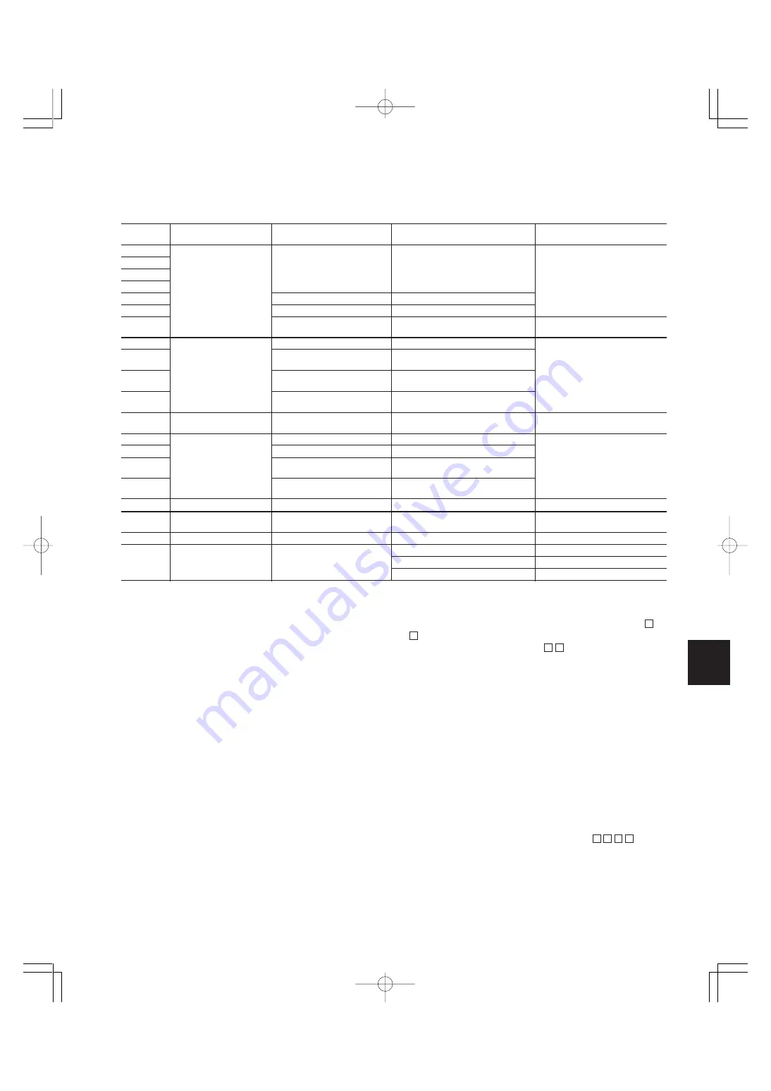
Function setting value (Recommended: G11S/P11S)
Other than the above functions, some of the basic functions such as base frequency, maximum frequency, acceleration/deceleration time, and
motor characteristics parameters should be set.
■
Tips
1. Refer to the basic wiring diagram for the line/
inverter changeover operation circuits.
• We have prepared a basic wiring diagram of the line/inverter
changeover operation circuits in addition to the system
configuration diagram. Refer to the basic wiring diagram
when configuring the control circuits.
•
To incorporate a line/inverter changeover operation circuit using the
switching command timing relay built-in the inverter, the function
code and data must be set taking into consideration the function
setting value (recommended value) set in advance.
• Reverse operation using the inverter is not possible.
2. Inspection of a forced line operation circuit
• If a fatal fault occurs in the inverter, commands issued by the
inverter circuit may not succeed in switching the system to
line operation. To execute line operation even in such a
condition, we recommend that you prepare a forced line
operation circuit separately.
• Please inquire separately for details about a forced line
operation circuit.
3. Adjusting the restart waiting time and other items
• Depending on the size of moment of inertia of the load
machine, factors such as the restart waiting time and restart
frequency fall rate may have to be adjusted.
4. Preparing external braking resistor
•
For G11S inverter of 10HP or smaller, a braking resistor is built into
the inverter. However, depending on conditions such as the level of
frequent operation or the load amount, an external resistor (DB -
) having a greater capacity may have to be connected. For 15HP
or larger inverter, a braking unit (BU - ) is required also.
•
When the braking resistor is connected externally, be sure to
disconnect the jumper wire (P(+), DB) of the built-in braking resistor
which has been connected at shipping. In addition, be sure to
insulate the disconnected portion.
5. Measures for reducing radio noise
•
This low-noise inverter switches its main circuits at high speed. At
locations where radio waves are weak, therefore, radio noise can
occur due to the effect of the wiring on the load side. We recom-
mend that you install a ferrite ring for reducing radio noise (ACL-40B
or ACL-75B) to reduce radio noise, use metal conduits for wiring,
and ground the control panel, motor, and conduits using lower
resistance values.
6. Full preparation to suppress harmonics with a DC
REACTOR
•
An exclusive terminal (P1, P(+)) for connecting a DC REACTOR is equipped
as standard. Connect the optional DC REACTOR (DCR -
) to
reduce harmonics on power supply side.
7. Suppression of inrush current when the power
supply is turned on
• FRENIC5000G11S/P11S series inverters have a built-in
circuit that suppresses inrush current that are generated
when the power supply is turned on.
E01
X1 terminal
(Function select)
E02
X2 terminal
E03
X3 terminal
E04
X4 terminal
E05
X5 terminal
E07
X7 terminal
E09
X9 terminal
E21
Y2 terminal
(Function select)
E22
Y3 terminal
E23
Y4 terminal
E24
Y5A,Y5C terminal
F14
Restart mode after momentary
power failure
(Mode select)
H13
Auto-restart(Restart time)
H14
(Freq. fall rate)
H15
(Holding DC voltage)
H16
(OPR command selfhold time)
H06
Fan stop operation
H07
ACC/DEC pattern
(Mode select)
H09
Start mode(Rotating motor pick up)
F26
Motor sound
(Carrier freq.)
Function
Name
Factory setting
Recommended setting value
Remarks
code
0:
Multistep freq. select (1 to 4 bits) [SS1]
1:
Multistep freq. select (1 to 4 bits) [SS2]
2:
Multistep freq. select (1 to 4 bits) [SS4]
3:
Multistep freq. select (1 to 4 bits) [SS8]
4:
ACC/DEC time selection (1 to 4 bits) [RT1]
6:
3-wire operation stop command [HLD]
8: Alarm reset
[RST]
1:
Frequency equivalence signal [FAR]
2:
Frequency level detection [FDT]
7: Overload early warning [OL]
15:
Auxiliary terminal for 52-1
[AX]
0: Inactive
0.5s
10.00Hz/s
460V: 470V
230V: 235V
999: Automatic
(Max. time)
0: Inactive
0: Inactive
(Linear)
0: Inactive
2: 2kHz
0:
Multistep freq. select (1 to 4 bits) [SS1]
1:
Multistep freq. select (1 to 4 bits) [SS2]
2:
Multistep freq. select (1 to 4 bits) [SS4]
15:
Line/Inverter changeover operation (50Hz) [SW50]
22: Interlock signal for 52-2
[IL]
6:
3-wire operation stop command [HLD]
9:
Trip command (External fault)
[THR]
11:
Line/Inv changeover (for 88) [SW88]
12: Line/Inv changeover
(for 52-2) [SW52-2]
13: Line/Inv changeover
(for 52-1) [SW52-1]
0: Inverter running
0: Inactive
(Trip and alarm when power failure occurs.)
0.1 to 10.0s
0.00 to 100.00Hz/s
460V: 400 to 600V
230V: 200 to 300V
0 to 30.0s
999: Automatic (Max. time)
1: Active
1: S-curve(weak)
2: S-curve(strong)
2: Active
15: 15kHz
10: 10kHz
6: 6kHz
For protecting the external braking
resistor, when it is used.
Set H13 to H16 also, if necessary.
Set the functions according to
individual system.
Set the function in accordance with
the load condition of the equipment.
For 75HP or smaller inverter.
For 100HP.
For 125 to 400HP inverter.
Chapter6-13(P26˜29).p65
07.8.9, 12:52
Page 27
Adobe PageMaker 6.5J/PPC
Summary of Contents for FRENIC5000G11S Series
Page 1: ......
Page 2: ......
Page 154: ...3 30 3 12 13 P23 30 65p 07 8 9 12 34 Page 30 Adobe PageMaker 6 5J PPC...
Page 166: ...4 12...
Page 182: ...3 12 13 P23 30 65p 07 8 9 12 34 Page 30 Adobe PageMaker 6 5J PPC 5 16...
Page 212: ...3 12 13 P23 30 65p 07 8 9 12 34 Page 30 Adobe PageMaker 6 5J PPC 6 30...
Page 234: ...MEMO Chapter8 4 P15 p65 07 8 9 12 57 Page 18 Adobe PageMaker 6 5J PPC...
Page 235: ......
Page 236: ......


