


2-70
Chapter 2
4. Standard RS-485 Interface
4.7.1 Changeover method for communication valid/
invalid
The changeover of the communication valid/invalid can be
performed by the multi-function command terminals (terminals
X1-X9) on the inverter. However, it is necessary to set the
inverter's multi-function command input terminals (E01 - E09:
X1-X9 terminals function) to the link operation selection (Data
24). If the multi-function command terminals have not been set
to the link operation selection, the communication becomes
valid automatically.
Note:
1) Since all memories are initialized at switching power supply on, the
command data and operation data must be write again from the
upstream units.
2) Even when the communication is invalid, the writing of command
data and operation data is valid, but it is not reflected by
SW1·SW2. The changeover without shock is possible by the way
where the data are set previously during the communication
invalid mode at first, then the mode is changed over to the
communication valid mode.
4.7.2 Link function (operation selection)
The setting (valid/invalid) for command data and operation
data during the communication valid period is possible
individually by the setting of " H30: Serial link (Function
selection)". (By making the communication always valid
without setting at the multi-function terminals, changeover for
the H30 data valid/invalid can change over the communication
valid/invalid, similar to the changeover with multi-function
command terminals.)
Note:
1) The communication valid bit of M14: Operating state becomes the
state signal of link option and not of RS-485.
2) When the command data and operation data are accessed from
RS-485, NAK is returned.
3) If the writing of functions is performed through this communication
during the writing of functions by the link, NAK (no writing right
error) is returned.
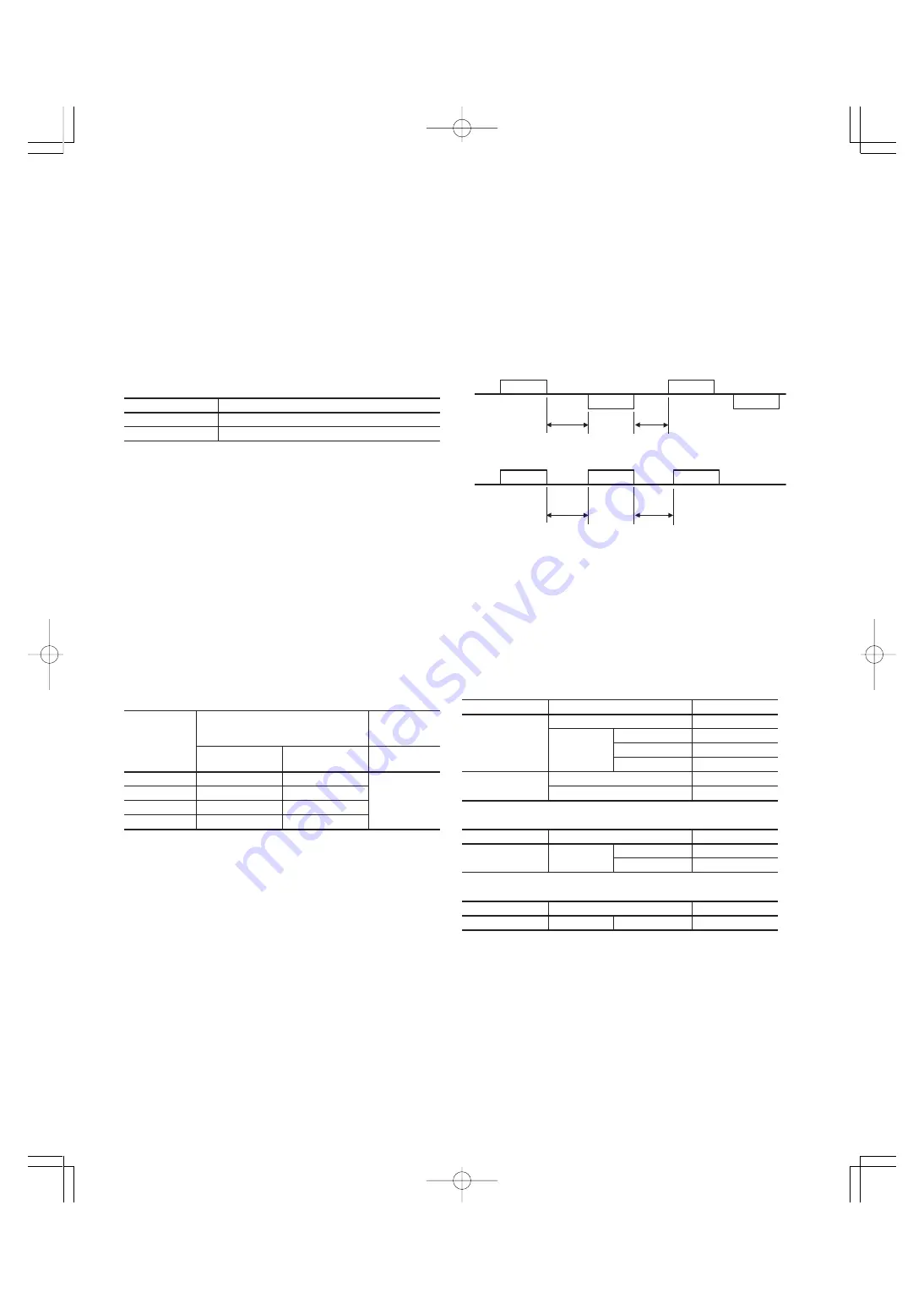
4.8 Response Time
Input terminals
State
OFF
Communication invalid mode
ON
Communication valid mode
Inverter
Host
t
2
t
1
Response
Query
Response
Query
t
1
+t
2
t
1
+t
2
Inverter
Host
Broadcast
Broadcast
Broadcast
4.8.1 Response interval time
The time till start of response sending after receiving a query
from the host such as PLC and PC can be set. By means of
the response interval time setting, it is possible to match the
sending timing even with the host having slow processing
speed.
- Response interval time (t
1
)
t
1
: Response interval time setting (H39) + t
d
t
d
: Processing time of inverter
t
d
≤
10ms
Frame
Processing
Command
Standard frame
Polling
R, E
Selecting
s01 - s07
W, A
s08 - s11
A
Function data
A
Option frame
Polling
g, h, i, j, k
Selecting
a, e, f, m
t
d
≤
100ms
Frame
Processing
Command
Standard frame
Selecting
s08 - s11
W
Function data
W
t
d
≤
5s
4.7.3 Coexistence of link (option) and RS-485
communication
When the link options (such as T link, field bus, etc.) are
mounted on the inverter, the communication is positioned as
described below and the functions are restricted.
Link : The operation through the communication (either one
of command data and operation data or both), the
operation monitoring, and the reading and changing
of functions are possible.
The communication
: The operation monitoring and the reading and
changing of functions as loader are possible (Opera-
tion through the communication is impossible).
Frame
Processing
Command
Standard frame
Selecting
H03
W
Note:
1) In case of the broadcast, the setting of response interval is invalid
(0s) because the inverter does not return the response, but it is
necessary to keep t
d
even in this case. (The all data received
during t
d
become neglected.)
2) If auto-tuning of P04 and A13 is written by single/continuous
functions, no response returns till completion of the tuning or
occurring of Er7. If tuning starting is commanded by the terminal
blocks or FWD/REV on the keypad panel during the invalid state of
communication, take care that the waiting state continues till
receiving of the starting command).
0
Invalid
Invalid
Invalid
1
Valid
Invalid
2
Invalid
Valid
3
Valid
Valid
Link function During communication is valid
H30
SW1
SW2
SW1, SW2
(Command data) (Operation data)
During
communication
is invalid
Chapter02J(P44˜74).p65
07.8.9, 12:27
Page 70
Adobe PageMaker 6.5J/PPC
Summary of Contents for FRENIC5000G11S Series
Page 1: ......
Page 2: ......
Page 154: ...3 30 3 12 13 P23 30 65p 07 8 9 12 34 Page 30 Adobe PageMaker 6 5J PPC...
Page 166: ...4 12...
Page 182: ...3 12 13 P23 30 65p 07 8 9 12 34 Page 30 Adobe PageMaker 6 5J PPC 5 16...
Page 212: ...3 12 13 P23 30 65p 07 8 9 12 34 Page 30 Adobe PageMaker 6 5J PPC 6 30...
Page 234: ...MEMO Chapter8 4 P15 p65 07 8 9 12 57 Page 18 Adobe PageMaker 6 5J PPC...
Page 235: ......
Page 236: ......


