4. Commissioning
4−15
Festo P.BE−MPA−EN en 0502b
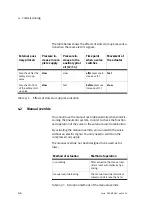
MPA valve terminal with MP or MPM connection
The LEDs indicate the switching status of the valve solenoid
coils.
LED
Switching position of the
valve
Meaning
out
basic position
logical 0 (no signal)
yellow alight
Switch position
or
basic position
logical 1 (signal present)
logical 1 but:
load voltage of the valves lies below the per
mitted tolerance range
(18 V ... 30 V DC)
Compressed air supply not OK
or
pilot exhaust blocked
or
servicing required
Table4/7:
Meaning of the LED display (MPA valve terminal with MP or MPM connection)
Summary of Contents for MPA-FB Series
Page 2: ......
Page 4: ...Contents and general instructions II Festo P BE MPA EN en 0502b...
Page 8: ...Contents and general instructions VI Festo P BE MPA EN en 0502b...
Page 17: ...Summary of components 1 1 Festo P BE MPA EN en 0502b Chapter 1...
Page 30: ...1 Summary of components 1 14 Festo P BE MPA EN en 0502b...
Page 31: ...Fitting 2 1 Festo P BE MPA EN en 0502b Chapter 2...
Page 47: ...Installation 3 1 Festo P BE MPA EN en 0502b Chapter 3...
Page 55: ...3 Installation 3 9 Festo P BE MPA EN en 0502b 1 2 3 Fig 3 2 Disconnecting the tubing...
Page 79: ...Commissioning 4 1 Festo P BE MPA EN en 0502b Chapter 4...
Page 96: ...4 Commissioning 4 18 Festo P BE MPA EN en 0502b...
Page 97: ...Diagnosis and error treatment 5 1 Festo P BE MPA EN en 0502b Chapter 5...
Page 139: ...Technical appendix A 1 Festo P BE MPA EN en 0502b Appendix A...
Page 151: ...Accessories B 1 Festo P BE MPA EN en 0502b Appendix B...
Page 161: ...Index C 1 Festo P BE MPA EN en 0502b Appendix C...
Page 162: ...C Index C 2 Festo P BE MPA EN en 0502b Contents C Index C 1...


