background image

GOT

Human Machine Interface

User’s Manual

Graphical Operator Terminal

A960GOT, A970GOT,

A975GOT, A985GOT

INDUSTRIAL AUTOMATION

MITSUBISHI ELECTRIC

MITSUBISHI ELECTRIC

Art. no.: 103490
01 04 2002
SH (NA)-4005-H

Summary of Contents for A960GOT

Page 1: ...GOT Human Machine Interface User s Manual Graphical Operator Terminal A960GOT A970GOT A975GOT A985GOT INDUSTRIAL AUTOMATION MITSUBISHI ELECTRIC MITSUBISHI ELECTRIC Art no 103490 01 04 2002 SH NA 4005 H ...

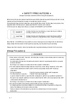
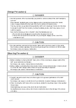
Page 2: ... user Design Precautions DANGER Some failures of the GOT main unit communication module communication board or cable may keep the outputs on or off An external monitoring circuit should be provided to check for output signals which may lead to a serious accident Not doing so can cause an accident due to false output or malfunction If a communication fault including cable disconnection occurs durin...

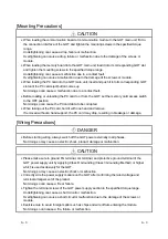
Page 3: ...wiring Run the above cables separately from such wiring and keep them a minimum of 100mm apart Not doing so noise can cause a malfunction Mounting Precautions DANGER Before installing or removing the GOT main unit to or from an enclosure always switch off the GOT power externally in all phases Not doing so can cause a module failure or malfunction Before loading or unloading the communication boar...

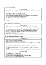
Page 4: ... so can cause the PC card data to be corrupted When taking out the PC card hold it with one hand and remove If removed without a hand support the PC card may drop resulting in breakage or damage Wiring Precautions DANGER Before starting wiring always switch off the GOT power externally in all phases Not doing so may cause an electric shock product damage or malfunction CAUTION Please make sure to ...

Page 5: ...onitoring special module monitoring or ladder monitoring read the manual carefully to fully understand how to operate the equipment During test operation never change the data of the devices which are used to perform significant operation for the system False output or malfunction can cause an accident Startup Maintenance Precautions DANGER When power is on do not touch the terminals Doing so can ...

Page 6: ...g Precautions DANGER Before changing the backlight always switch off the GOT power externally in all phases when the GOT is connected to the bus the PLC CPU power must also be switched off externally in all phases and remove the GOT main unit from the enclosure Not switching the power off in all phases may cause an electric shock Not removing the unit from the enclosure can cause injury due to a d...

Page 7: ...12 8 3 Partial additions Chapter 1 Section 1 1 2 2 2 4 3 2 3 3 4 1 6 1 6 3 6 4 6 6 6 10 7 4 8 2 Appendix 1 2 Addition Section 6 1 6 6 1 7 6 15 A985GOT TBA V A985GOT TBD V Jun 2001 SH NA 4005 F Partial corrections Section 1 2 1 2 3 Partial additions Section 1 1 1 2 2 2 2 3 2 1 3 2 2 3 2 3 3 3 1 3 3 2 4 2 6 1 2 6 1 3 6 1 4 6 5 3 6 7 1 6 14 2 8 2 Appendix 2 Addition Section 2 3 1 2 3 2 2 3 3 2 3 4 2 ...

Page 8: ...1 9 2 SYSTEM CONFIGURATION 2 1 to 2 9 2 1 Overall Configuration 2 1 2 2 Component List 2 2 2 3 Cautions on use of EMC command and low voltage command compatible products 2 5 2 3 1 Caution points when using PC card Flash PC card 2 5 2 3 2 About Modules that the EMC directive do not apply to 2 5 2 3 3 Connection Format 2 6 2 3 4 When the communication module board is used 2 7 2 3 5 About the Cable U...

Page 9: ... 6 2 1 Mounting and dismounting procedures 6 18 6 3 Protective Sheet 6 19 6 3 1 Protective sheet types 6 19 6 3 2 Mounting procedure 6 19 6 4 Memory Board 6 20 6 4 1 Memory board types 6 20 6 4 2 Mounting procedure 6 20 6 5 PC Card 6 21 6 5 1 PC card types 6 21 6 5 2 Battery changing timing and method 6 22 6 5 3 Loading and unloading procedures 6 23 6 6 Communication Board 6 25 6 6 1 Connection bo...

Page 10: ...ily Inspection 7 2 7 3 Periodic Inspection 7 2 7 4 Backlight for Liquid Crystal 7 3 7 4 1 How to change the backlight for liquid crystal 7 4 8 ERROR CODES AND ERROR MESSAGES 8 1 to 8 16 8 1 Definition of the Error Codes and Messages Displayed 8 1 8 2 Error Code and Error Message List 8 2 8 3 Precautions for use of flash PC card 8 6 8 4 Precautions for installation of ROM_BIOS 8 7 8 5 Troubleshooti...

Page 11: ... the screen makeup of the GT Designer the general description of various monitoring functions the procedure for displaying the monitor screen on the GOT and how to use the help function Available as option SH 080117 13JF95 GOT A900 Series User s Manual GT Works Version5 GT Designer Version5 compatible Connection System Manual Gives the specifications system configuration setting method and connect...

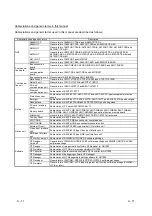
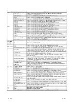
Page 12: ... and A9GT 70LTS type backlights Debug stand Abbreviation of A9GT 80STAND and A9GT 70STAND type debug stand PC card memory card Abbreviation of PC card with PCMCIA Ver 2 1 Memory board Abbreviation of A9GT FNB A9GT FNB1M A9GT FNB2M A9GT FNB4M A9GT FNB8M A9GT QFNB A9GT QFNB4M A9GT QFNB8M type option function memory board Attachment Generic term of A77GT 96ATT A87GT 96ATT A87GT 97ATT attachments Ten ...

Page 13: ...00H C200H series C200HX C200HG C200HE CQM1 C1000H C2000H CV500 CV1000 CV2000 CVM1 CPU11 CVM1 CPU21 CS1 CPU unit Yasukawa PLC Generic term of GL60S GL60H GL70H GL120 GL130 CP 9200SH CP 9300MS MP 920 MP 930 MP 940 CP 9200 H and PROGIC 8 CPU unit SLC500 Series Generic term of SLC500 20 SLC500 30 SLC500 40 SLC5 01 SLC5 02 SLC5 03 SLC5 04 SLC5 05 MicroLogix1000 Series Generic term of 1761 L10BWA 1761 L...

Page 14: ...GOT EBA EU User s Manual Hardware 2 A985GOT TBA TBD V User s Manual Hardware 2 1 1 Affix a caution plate in a conspicuous position such as memory card interface part Affix a caution plate on a communication module during its use The caution plate is included only in the following GOT models A97 GOT except EU Hardware version L jun 2001 or later A960GOT except EU Hardware version H jun 2001 or late...

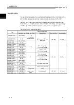
Page 15: ...A 100 to 240VAC A985GOT TBD 24VDC A985GOT TBA EU 100 to 240VAC High luminance TFT color liquid crystal 800 600 31 12inch A975GOT TBA 100 to 240VAC A975GOT TBD 24VDC Wide viewing angle TFT color liquid crystal A975GOT TBA B 100 to 240VAC A975GOT TBD B 24VDC A975GOT TBA EU 100 to 240VAC 256 High luminance TFT color liquid crystal A970GOT TBA 100 to 240VAC A970GOT TBD 24VDC Wide viewing angle TFT col...

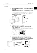
Page 16: ...ontrol box or the like A870GOT A970GOT A870GOT A970GOT 2 User friendly multimedia display device Clear high grade display has been achieved by 256 color representation A975GOT A985GOT V only Ear appealing information transmission has also been achieved by supporting speech output using the Windows WAV file Line 1 stopped 3 Fast data transfer of OS and screen data by memory card The PC card for OS ...

Page 17: ...ccurrence counting function cumulative failure time totalizing function and history printing function and start ladder monitoring with the corresponding device searched with a single keystroke at the failure detail display time 7 Improvement of safety by upgraded security function Supporting the operation protective function using up to 16 levels of passwords the GOT can hide the display or disabl...

Page 18: ...eleased by the product 30M 230MHz QP 30dBµ V m 30m measurement 1 230M 1000MHz QP 37dBµ V m 30 m measurement EN50081 2 1995 EN55011 Conduction noise 2 Measure the emission released by the product to the power line 150K 500kHzQP 79dB Mean 66dB 1 500K 30MHz QP 73dB Mean 60dB EN61000 4 2 Static electricity immunity 2 Immunity test by applying static electricity to the module enclosure 4kV contact disc...

Page 19: ... the main unit reduce the clearance as much as practicable The leakage of radio waves can be suppressed by the direct application of an EMI gasket on the paint surface Our tests have been carried out on a panel having the damping characteristics of 37 dB max and 30 dB mean measured by 3 m method with 30 to 300 MHz 2 Connection of power and ground wires Ground and power supply wires for the GOT mus...

Page 20: ...ufacturer SCHAFFNER SCHAFFNER TDK Rated current 3A 6A 3A Rated voltage 250V The precautions required when installing a noise filter are described below 1 Do not bundle the wires on the input side and output side of the noise filter When bundled the output side noise will be induced into the input side wires from which the noise was filtered Filter Induction Output side device side Input side power...

Page 21: ...bove Directive is not guaranteed Each manufacturer who fabricates such device should make the final judgement about the application method of the Low Voltage Directive and the product compatibility 1 3 1 Standard applied for GOT The standard applied for GOT is EN61010 1 safety of devices used in measurement rooms control rooms or laboratories 1 3 2 Power supply The insulation specification of the ...

Page 22: ...ope with the pollution level 2 so use in an environment with pollustion level 2 or better Pollution level 1 An environment where the air is dry and conductive dust does not exist Pollution level 2 An environment where conductive dust does not usually exist but occasional temporary conductivity occurs due to the accumulated dust Generally this is the level for inside the control box equivalent a co...

Page 23: ...h the Low Voltage Directive s requirements for isolation between the primary and secondary circuits 2 Insulation requirements Dielectric withstand voltages are shown in the following table Intensive Insulation Withstand Voltage Installation Category II source IEC664 Rated voltage of hazardous voltage area Surge withstand voltage 1 2 50 µs 150 VAC or below 2500V 300 VAC or below 4000V ...

Page 24: ...vailable Compatible with stereo mini jack Communication module e g A7GT J71AP23 Commercially available Based on JEIDA Ver4 2 Based on PCMCIA2 1 Pinter Commercially available Window compatible printer CRT Commercially available External I O module A9GT 70KBF e g A9GT BUSS Video input unit A9GT 80V4 RGB input unit A9GT 80R1 1 1 1 1 Communication board 1 2 1 3 1 1 For details of the system configurat...

Page 25: ...ow Voltage Directive compliant product A970GOT LBA 26cm 10inch STN monochrome liquid crystal 100 to 240VAC A970GOT A970GOT LBD 26cm 10inch STN monochrome liquid crystal 24VDC A960GOT EBA 23cm 9inch 2 color display high luminance EL 100 to 240VAC A960GOT EBD 23cm 9inch 2 color display high luminance EL 24VDC A960GOT A960GOT EBA EU 23cm 9inch 2 color display high luminance EL 100 to 240VAC EMC Direc...

Page 26: ...atible Commercially available SRAM type PC card based on JEIDA Ver4 2 based on PCMCIA2 1 Commercially available flash PC card based on Compact FlashTM Compact FlashTM is a trademark of Sun Disk A9GTMEM 10MF For GOT Memory 16M byte hardware version D or later flash PC card formatted A9GTMEM 20MF For GOT Memory 32M byte hardware version D or later flash PC card formatted PC card memory card A9GTMEM ...

Page 27: ...able length 3m D sub 9 pin at both ends For connection between GOT and computer link module For connection between GOT and personal computer for data transfer AC30R2 Cable length 3m D sub 25 pin at both ends AC30N2A Cable length 3m D sub 25 pin at both ends For connection between GOT and personal computer for data transfer 9 pin conversion connector required RS 232C cable 4 For connecting the GOT ...

Page 28: ...tion impossible When the PC card is used Type Commercial PC card SRAM type Flash PC card A9GTMEM MF Commercial flash PC card A985GOT TBA EU A975GOT TBA EU A970GOT TBA EU A970GOT SBA EU A960GOT EBA EU 2 3 2 About Modules that the EMC directive do not apply to The EMC directive is not applicable when using the modules below Item Type Bus connection board A9GT QBUSS A9GT QBUS2S Bus connection module ...

Page 29: ... 0105 E 0105 A L 0105 CC Link connection Remote device station Ethernet connection Y 0203 Y 0203 M 0203 E 0203 Q 0203 How to read the table The table indicates the GOT compatible hardware version for each connection pattern and the compatibility date The compatibility date of the GOT compatible with hardware version A is not indicated Please use the GOT whose hardware version is later than that de...

Page 30: ...out the applicability of the EMC directive 2 3 4 When the communication module board is used If the EMC directive is applicable use the communication module board shown below Available May 2001 If a communication module board other than those shown below is used it will not apply to the EMC directive Connection format Communication module board Bus connection A9GT BUSS Hardware version C or later ...

Page 31: ...or each GOT are shown below Type Compatible software package A985GOT TBA V A985GOT TBD V SW5D5C GTWORKS E Version F or later SW5D5C GOTR PACKE Version F or later A985GOT TBA EU A985GOT TBD SW0D5C GTWORKS E Version A or later SW1D5C GOTRE PACK Version C or later A975GOT TBA B EU A975GOT TBD B A970GOT TBA B EU A970GOT TBD B SW0D5C GTWORKS E Version A or later SW1D5C GOTRE PACK Version A or later The...

Page 32: ... version of the additional base for duplex system please refer to the DATE column on the rating plate that is adhered to the part as shown in the illustration below MITSUBISHI PROGRAMMABLE CONTOROLLER MITSUBISHI ELECTRIC CORP JAPAN DATE 9806 B Version of additional base for duplex system Magnified illustration of rating plate CAUTION 2 Notes on 5V DC supply for the additional base A68RB for duplex...

Page 33: ...tude 2000 m 6562 ft max Installation site Inside control box Overvoltage category 2 II or less Contamination level 3 2 or less 1 For A975GOT TBA TBD B and A970GOT TBA TBD B it becomes 0 to 55 C 2 Indicates the element in the distribution system between the public electricity grid and the mechanical equipment inside the premises that the relevant device is assumed to be connected to Category II app...

Page 34: ...ce For connection of personal computer for bar code reader connection 1 channel Printer interface 3 For printer connection 1 channel CRT interface 4 For CRT connection SVGA 1 channel Speech output terminal For external speaker connection 3W 3W or higher recommended stereo mini jack 1 channel each for L R 2Vp p 0 4mW for rated load 10kΩ replayable speech file Windows WAV format 8 000kHz 16 bit mona...

Page 35: ...m 1 0µs maximum 500 3 Minimum 2µs Note 2 BUSY rises after fall of STROBE Note 3 ACKNLG is sent within 10µs after fall of BUSY Type GOT connector Cable connector Cable connector cover 10220 52A2JL 10120 6000EL insulation displacement type connector 10320 3210 000 Sumitomo 3M make No Signal No Signal No Signal No Signal 1 CHASIS GND 6 NC 11 DATA8 16 DATA3 2 ACKNLG 7 INIT 12 DATA7 17 DATA2 3 DATA6 8 ...

Page 36: ...ng timing Timing chart Video signal 20 854ms VIDEO analog 0 7VP P H SYNC Horizontal cycle 26 694ms 0 626ms 0 877ms Horizontal cycle time 3 337ms V SYNC Video signal 16 683ms VIDEO analog 0 7VP P Vertical cycle 16 683ms 0 027ms 0 053ms Vertical cycle time 0 587ms Type 15 pin shrink D sub female screw fixing type DDK make 17HE R13150 73MC2 5 4 3 2 1 10 9 8 7 6 15 14 13 12 11 No Signal name Direction...

Page 37: ... GOT side CRT side NC NC NC NC R RGND G GGND B BGND NC NC NC NC NC NC NC 1 6 2 7 3 8 5 10 13 14 4 9 11 13 14 75Ωcoaxical Twisted pair HSYNC VSYNC 5 When parts must be changed consult your sales representative 6 The screen save and back light OFF functions of the GOT and operator detect sensor function are used to prevent the display of the screen from being printed and prolong the service life of ...

Page 38: ...arallel printer connection 1 channel Speech output terminal For external speaker connection 3W 3W or higher recommended stereo mini jack 1 channel each for L R 2Vp p 0 4mW for rated load 10kΩ replayable speech file Windows WAV format 8 000kHz 16 bit monaural 8 s speech file Buzzer output Single tone tone length adjustable Display section h 7 41 000 Operating ambient temperature 25 C 50 000 Operati...

Page 39: ...ata Data backup power supply is not needed 4 Note that either of the communication board slot and communication module interface may only be used 5 Refer to the 3 2 1 for details on the specifications are those of the printer interface 6 When parts must be changed consult your sales representative 7 The screen save and back light OFF functions of the GOT and operator detect sensor function are use...

Page 40: ...h and 25 to 60Hz noise frequency Dielectric withstand voltage 1500VAC for 1 minute across AC external terminals and earth 2830VAC for 1 second for EU 500VAC for 1 minute across DC external terminals and earth Insulation resistance 10MΩ or larger by insulation resistance tester External output Transistor output 2 points RUN OUTPUT Insulation system Photocoupler insulation Rated load voltage 12 24VD...

Page 41: ...SBA EU A970GOT LBA A960GOT EBA A960GOT EBA EU 100VAC 59VA or less Communication module 200VAC 74VA or less 100VAC 69VA or less Communication board 200VAC 86VA or less 3 3 2 GOT with DC type input power supply When the communication board or communication module is fitted to the GOT whose input power supply is DC type power consumption is as listed below Power Consumption Apparent Power Communicati...

Page 42: ...T 4 memory card access switch Used to set the condition of access to the PC card when it is loaded during power on Factory set to OFF OFF Access from GOT to PC card inhibited ON Access from GOT to PC card enabled 5 memory card LED Indicates whether the PC card may be loaded unloaded or not OFF PC card may be loaded unloaded When switch 4 is OFF ON PC card must not be loaded unloaded When switch 4 ...

Page 43: ...r connection of personal computer and bar code reader 14 Option module interface For option module loading for future extension 15 Terminal block For power input and external output 16 Communication board slot Slot for communication board loading 17 Memory board slot Slot for memory board loading 18 Screw hole for attaching memory board Screw hole used to attach the memory board 19 Mounting fixtur...

Page 44: ...PC card when it is loaded during power on Factory set to OFF OFF Access from GOT to PC card inhibited ON Access from GOT to PC card enabled 4 memory card LED Indicates whether the PC card may be loaded unloaded or not OFF PC card may be loaded unloaded When switch 3 is OFF ON PC card must not be loaded unloaded When switch 3 is ON 5 Communication module interface Interface for loading the communic...

Page 45: ...For power input and external output 14 Communication board slot Slot for communication board loading 15 Memory board slot Slot for memory board loading 16 Screw hole for attaching memory board Screw hole used to attach the memory board 17 Mounting fixture fitting portion For mounting fixture fitting 18 Protective ground terminal 1 For earthing For safety please make sure to ground this terminal 19...

Page 46: ... personal computer Install personal computer installed OS program and monitor screen data into GOT 1 Install basic OS communication driver extension function OS into GOT 2 Reset GOT power on completion of installation 3 Download screen data created on personal computer Install personal computer installed OS program and monitor screen data to PC card 1 Copy basic OS communication driver extension f...

Page 47: ...5 2 5 2 MELSEC GOT 5 ROUGH PRE OPERATION PROCEDURE 5 MEMO ...

Page 48: ... short circuit or malfunction due to the damage of the screws or module When loading the communication board or communication module to the GOT main unit fit it to the connection interface of the GOT and tighten the mounting screws in the specified torque range Undertightening can cause a drop failure or malfunction Overtightening can cause a drop failure or malfunction due to the damage of the sc...

Page 49: ... cause a module malfunction or failure 1 Do not drop the module or give it strong impact Doing so can cause a failure because the display device is made of glass 2 Do not remove the printed circuit board of the module from the case Doing so can cause a failure 3 When mounting the main unit to a control box or the like set the display section as shown below When the temperature inside the enclosure...

Page 50: ...on board 140 5 51 or more A97 GOT A9GT BUSSU BUS2SU 15 0 59 or more A985GOT V A960GOT A9GT BUSSU BUS2SU 30 1 18 or more When using a cable prepared by user please consider the connector cover to be used and the bending radius of the cable When using a bar code reader please consider the dimensions of the connector to be used and the bending radius of the cable Part B size When using a PC card or a...

Page 51: ...ting position Mounting position c How to mount and fix the mounting fixture is given below 1 Insert the mounting fixture into the fixture fitting portion of the GOT main unit 2 Tighten and fix the mounting screw in the specified torque range POINT Do not paint at the sections where the mounting fixture and control panel contact Instead provide a conductivity between the mounting fixture and contro...

Page 52: ...5GOT TBD A970GOT TBA B A970GOT TBD B A970GOT TBA A970GOT TBD A970GOT SBA A970GOT SBD A970GOT LBA A970GOT A970GOT LBD Version L jun 2001 or later A960GOT EBA A960GOT A960GOT EBD Version H jun 2001 or later 2 When the conventional GOT s protective ground terminal has the wire fixed remove or insulate the wire 2 How to use the external outputs a RUN Outputs whether the GOT operation is normal or abno...

Page 53: ... as shown in the illustration and be sure to attach a ferrite core TDK type ZCAT3035 1330 within the range shown below Lead the power wire and ground wire as shown in Section 1 1 2 2 Always ground the LG and FG wires For A985GOT For Bus connection For RS 422 connection A97 960GOT INPUT 100 240VAC LG FG AC LG FG GOT terminal block Ferrite core within 100mm 3 94 inch within 50mm 1 97 inch INPUT 100 ...

Page 54: ...the control panel within 120mm 4 72inch INPUT 100 240VAC LG FG GOT terminal block Ground to the control panel within 120mm 4 72inch INPUT 100 240VAC LG FG Ferrite core within 70mm 2 76 inch GOT terminal block Ground to the control panel within 120mm 4 72inch c When connecting CC Link use the grounding wire of the FG1 terminal on the CC Link communication module to connect to the FG terminal of the...

Page 55: ...both ends of the cable to the lengths shown below Peel the sheath with the length shown below at both ends of the cable and expose the shield braided wire for grounding 130 130 GOT side PLC GOT side Ferrite Core ZCAT3035 1330 Within 360 Within 360 40 40 Unit mm inch Ground wires 280mm 11 0inch 14 17 1 57 1 57 14 17 5 12 5 12 2 For other cables between GOT and base unit Wind cable shield material a...

Page 56: ... QC30R2 Peel the sheath with the length shown below at both ends of the cable and expose the shield braided wire for grounding 130 130 GOT side PLC side Within 230 Within 300 40 40 Unit mm inch Ferrite Core ZCAT3035 1330 5 12 9 06 11 81 1 57 1 57 5 12 2 RS 422 cable For AC30 100 300R4 25P For A985GOT Wind cable shield material around the cable and pull out the grounding braided wire of the cable s...

Page 57: ...0 5 90 c Computer link connection 1 For RS 232C cable The RS 232C cable used to connect the GOT the computer link unit and PLC CPU with computer link function must be prepared by the user The RS 232C cable connection diagram and the connector are as follows Connection diagram If D sub 9 pin is used for the connector of the computer link unit A1SJ71QC24 R2 A1SJ71UC24 R2 A1SJ71C24 R2 A1SCPUC24 R2 A2...

Page 58: ...facturing cable Make a twisted pair for each signal and SG Connect the braided shield to the connector shell both ends The cable used for the Mitsubishi EMC Directive compatibility test had the following specifications Item Specification Cable type Twisted pair shield cable Conductor section area mm 2 0 2 Connector and connector cover GOT connector Use the connector matching the following model fo...

Page 59: ...created cable Refer to the GOT A900 series User s Manual GT Works Version5 GT Designer Version5 compatible Connection System Manual for information about the cable creation method Wind cable shield material around the cable and pull out the grounding braided wire of the cable shield material with the length shown below Pass the grounding braided wire on the programmable logic controller side throu...

Page 60: ... 40 Unit mm inch Ferrite Core ZCAT3035 1330 Within 230 5 12 5 12 9 06 9 06 1 57 1 57 e Ethernet Connection Twisted pair shielded cable Peel the sheath with the length shown below at both ends of the cable and expose the shield wire for grounding GOT side Ethernet module side Within 230 9 06 Within 400 15 75 40 1 57 40 1 57 Unit mm inch 130 5 12 Ferrite core ZCAT3035 1330 f Printer cable Wind cable...

Page 61: ...the cable Ground the cable grounding sections and grounding wire to the control panel where the GOT and base unit are grounded Grounding to the panel with the cable clamps Cable clamps Bus connection cable For A8GT C100 C200 300EXSS A8GT C100 200 300BS ground the shield braided wire and grounding wire to the panel with a cable clamp AD75CK Ground the shield braided wire of the RS 232C cable CC Lin...

Page 62: ...range Left right 80 Detection delay time sec 0 to 4 1 The temperature difference from the background must be 3 1 C or more 2 The movement speed is 0 3 to 2 0m s Note that the human sensor may react even under conditions that those above The details of the detection range are as shown below A985GOT V 80 each in up down left right directions 1m 3 Precautions for using human sensor If there is glass ...

Page 63: ... Version5 Compatible Connection System Manual Image data Camera power pack Video camera Video camera Vision sensor AS50VS or other A985GOT V A9GT 80V4 The camera power pack may be necessary depending on the vision sensor used 1 Video display specifications Item Specifications Image display color color 65536 Color NTSC format PAL format interlaced format Video input format Monochrome 1 EIA format C...

Page 64: ...f the system configuration refer to the GOT A900 Series User s Manual GT Works Version5 GT Designer5 Compatible Connection System Manual You can not show the computer s display on the computer monitor and the A985GOT V at the same time When connecting to a personal computer RGB output type vision sensor When using the RGB output type vision sensor and connecting to a video camera A985GOT V A985GOT...

Page 65: ...ust be removed When using the communication module the slot cover need not be removed 1 Loosen the mounting screws 2 pcs which secure the slot cover 2 Remove the slot cover Save the removed slot cover 2 Mounting After loading the memory board the slot removed must be mounted again 1 Insert the convex portion of the slot cover into the concave portion of the GOT 2 Securely push the slot cover and t...

Page 66: ...UBISHI logotype can be removed A9GT 70PSC Transparent protective sheet for A975 970GOT MITSUBISHI logotype can be removed A9GT 60PSC Transparent protective sheet for A960GOT MITSUBISHI logotype can be removed 6 3 2 Mounting procedure 1 From the display section of the GOT peel off the sheet applied before shipment from the factory or the old protective sheet 2 Peel off the release film of the new p...

Page 67: ...memory extension 4M byte A9GT FNB8M For optional function OS storage built in memory extension 8M byte MELSEC A FX Ladder monitor compatible 6 4 2 Mounting procedure 1 Refer to Section 6 2 and remove the slot cover 2 Load the memory board into the memory board loading slot the memory board mounting screws 3 Tighten and fix the memory board mounting screws in the specified torque range 4 Refer to S...

Page 68: ...y of the following GOTs is used A975GOT TBA B A975GOT TBD B A975GOT TBA A975GOT TBD A970GOT TBA B A970GOT TBD B A970GOT TBA A970GOT TBD A970GOT SBA A970GOT SBD A970GOT LBA A970GOT LBD A960GOT EBA A960GOT EBD Condition 2 The function version of the GOT used is version A or later Confirm the function version of the GOT on the rating plate on the GOT rear surface DATE 0010AP MADE IN JAPAN LISTED 80M1...

Page 69: ...en For the details refer to the GOT A900 Series Operating Manual GT Works Version5 GT Designer Version5 compatible Extended Option Functions Manual 2 Using the alarm list display system alarm function to check When a battery low occurs the error warning message and battery low error code appear on the monitor screen For the details refer to the GT Designer Help Function 2 Battery life For the PC c...

Page 70: ...memory card LED goes off the PC card can be loaded unloaded while power is on PC card top face 2 When loading the PC card into the GOT insert and load it into the memory card interface with its top face up 2 Dismounting OFF ON 1 Set the memory card access switch of the GOT to OFF and make sure that the memory card LED goes off When the PC card LED goes off the memory card can be loaded unloaded wh...

Page 71: ... unloaded while power is on 2 Open the memory card interface cover 3 Insert the PC card into the memory card interface with the PC card facing up Place a PC card on the memory card interface section of the GOT and slide it in place 2 Dismounting OFF ON 1 Set the memory card access switch of the GOT to OFF and make sure that the memory card LED goes off When the PC card LED goes off the memory card...

Page 72: ...oller CPU A9GT BUS2S For multidrop bus connection small connector type For A QnA Motion controller CPU A9GT RS4 For Direct connection to CPU Computer link connection Microcomputer connection and RS 422 connection Without clock function A9GT RS2 For Direct connection to CPU Computer link connection Microcomputer connection and RS 232C connection Without clock function A9GT RS2T For Direct connectio...

Page 73: ...ed Type Description A9GT QBUSS A9GT QBUS2S SW0D5C GTWORKS E Version A or later SW3D5C GOTRE PACK Version C or later A9GT BUSS A9GT BUS2S A9GT RS4 A9GT RS2 SW0D5C GTWORKS E Version A or later SW1D5C GOTRE PACK Version A or later A9GT RS2T SW0D5C GTWORKS E Version A or later SW1D5C GOTRE PACK Version J or later ...

Page 74: ...LSECNET II optical link connection for use as local station A7GT J71AR23 For MELSECNET II coaxial link connection for use as local station A7GT J71AT23B For MELSECNET B connection for use as local station A7GT J71LP23 For MELSECNET 10 optical loop network connection for use as ordinary station A7GT J71BR13 For MELSECNET 10 coaxial bus network connection for use as ordinary station A8GT J61BT13 For...

Page 75: ...he printer usable is any of the printers having the following specifications standard whose operations have been checked by Mitsubishi ESC P24 J84 compliant printer ESC P command compatible color compatible Hewlett Packard printers PLC command compatible 6 8 2 Connection procedure 1 Plug the GOT side connector of the printer cable to the printer interface at the bottom of the GOT 2 Connect the GOT...

Page 76: ...evice type A commercially available speaker compatible with the stereo mini jack can be used as the speech output device The replayable file format is the Windows WAV file format 8000kHz 16 bit monaural and speech output is up to 8 seconds per file Speech output over 8 seconds is cut 6 9 2 Connection procedure 1 Insert and connect the stereo mini jack of the commercially available speaker into the...

Page 77: ...usting screw A960GOT mounting surface A975 970GOT mounting surface 1 The used mounting surface of the debug stand depends on the GOT mounted For the A9GT 70STAND note that the mounting surface used changes with the GOT mounted The figure on the left shows that the A975 970GOT is mounted 2 Adjust the GOT mounting angle with the angle adjusting screw of the debug stand 3 Put the GOT into the front f...

Page 78: ...o 6 11 2 Connecting procedure 1 To the RS 232C interface that is provided on the lower part of the GOT choose and connect one from the following the connector for the bar code reader the connector for the power supply module and the connector on the GOT for the RS 232C cable The connecting method differs depending on the kind of bar code reader that will be used Please note that the bar code reade...

Page 79: ...odule 6 12 2 Mounting procedure GOT A9GT 70KBF 1 Mount the external I O module on the option module interface GOT 2 Tighten and fix the mounting screws 2 pcs of the external I O module in the specified torque range When an external I O interface module is used either SW0D5C GTWORKS E version A or later or SW1D5C GOTRE PACK version C or later is required For details of the external I O function ref...

Page 80: ... 1024 RD17MX Mitsubishi Electric make 17inch 1280 1024 RDF19X Mitsubishi Electric make 19inch 1600 1200 CRT display RD19NF Mitsubishi Electric make 19inch 1600 1200 RDT150S Mitsubishi Electric make 15inch 1024 768 TFT display RDT180S Mitsubishi Electric make 18 1inch 1280 1024 6 13 2 Connecting procedure 1 Plug the GOT side connector of the CRT cable into the SVGA interface at the GOT bottom The C...

Page 81: ...pe from the rear surface of the attachment Installation panel Attachment 2 Install the attachment securely taking care so that it is positioned correctly in the installation panel mounting hole If the installation panel is dirty the attachment may fall causing injury Ensure to clean the installation panel by wiping it off before installation of the attachment GOT Installation panel 3 Insert the GO...

Page 82: ...ace module 6 15 2 Mounting procedure GOT A9GT 80V4 or A9GT 80R1 1 Mount the video RGB interface module on the option module interface GOT 2 Tighten and fix the mounting screws 2 pcs of the video RGB input interface module in the specified torque range To use video input interface module SW5D5C GTWORKS E version F or later or SW5D5C GOTR PACKE version F or later will be required To use RGB input in...

Page 83: ...e injury due to a drop CAUTION Do not disassemble or modify the module Doing so can cause a failure malfunction injury or fire Do not touch the conductive and electronic parts of the module directly Doing so can cause a module malfunction or failure The cables connected to the module must be run in ducts or clamped Not doing so can cause the module or cable to be damaged due to the dangling motion...

Page 84: ...iring changed Number Inspection Item Inspection Method Criterion Action Display section 0 to 40 C Ambient temperature Other portions 0 to 55 C Ambient humidity 10 to 90 RH 1 Surrounding environment Atmosphere Make measurement with thermometer or hygrometer Measure corrosive gas No corrosive gas For use in enclosure temperature inside enclosure is ambient temperature 100 to 240VAC Measure voltage a...

Page 85: ...OT TBD A985GOT TBA EU A9GT 80LTT Backlight A975GOT TBA Hardware version C or earlier A975GOT TBD Hardware version A A9GT 70LTT Backlight 1 A975GOT A975GOT TBA Hardware version C and above A975GOT TBD Hardware version B and above A975GOT TBA B A975GOT TBD B A975GOT TBA EU A9GT 70LTTB Backlight 1 A970GOT TBA Hardware version C or earlier A970GOT TBD Hardware version A A9GT 70LTT Backlight 1 A970GOT ...

Page 86: ...s 4 pcs in the back of the GOT with a screwdriver When the GOT used is the A985GOT remove 5 fixing screws A975GOT A970GOT A960GOT Bottom A985GOT Bottom Hold down portion a and pull out the connector in the direction of b a b 4 After removing the fixing screws hold down the fixing catches 4 places at top bottom right and left and remove the display cover from the GOT when the GOT used is the A975GO...

Page 87: ... the backlight from the connector of the display device Remove the connectors in two places at top and bottom of the device for the STN or the connector in one place at top for the TFT 6 Remove the backlight from the display device Remove two backlights at top and bottom of the display for the STN or one at top for the TFT 7 Fit a new backlight in the reverse procedure of removal To install the di...

Page 88: ...0 to 499 Section 8 2 MNET 10 500 to 799 Network System Reference Manual of MNET 10 2 CC Link 800 to 999 CC Link System Master Local Module User s Manual 3 QnACPU 1000 to 9999 Value of SD0 User s Manual of QnACPU where GOT is connected 1 Take action with reference to the section explaining the link special relay of the error code 9000 For example when the error of error code 210 has occurred 210 90...

Page 89: ...range The comment number set for comment display does not exist or the comment file does not exist Create the comment file and download it to the GOT 309 Device read error Device data read caused an error Correct device 310 Specified monitor data not found or outside range 1 The specified base screen window screen does not exist in the project data 2 The specified base screen window screen is outs...

Page 90: ...attery voltage of the PC card is low Change the battery of the PC card 340 Printer in error or power off 341 Printer fault The printer is faulty or its power is not on 1 Check the printer 2 The Printer switch it on 342 The fuse of KBF module was blown A fault occurred in the external I O interface module 1 If external power 24VDC is not supplied supply external power 2 If external power is supplie...

Page 91: ... the divisor of 0 370 Contradiction in magnitude relationship of upper and lower limit values Upper and lower limit values have been set as upper limit lower limit Check the upper and lower limit value setting and correct them to be upper limit lower limit 402 Communication time out Time out error occurred during communication 1 Check for any disconnected cable or improperly fitted communication b...

Page 92: ... do not use the same station number 1 Check the station number of the GOT on the utility screen of the GOT 2 Check the station number set as the screen data 3 Check the station number set in the Ethernet setting Use the station number of the PLC side Ethernet module set in the parameter setting of GX Developer 448 Devices outside file register and other ranges included Devices specified are outsid...

Page 93: ...ansfer error 1 Take the action corresponding to the error Refer to Section 8 2 2 Choose UTILITY MENU SELF CHECK MEMCARD CHECK on the GOT unit If the error is detected the following dialog box appears For full information on the utility menu refer to GOT A900 Series Operating Manual GT Works Version5 GT Designer Version5 compatible Extended Option Functions Manual MEMORY CARD WRITE READ CHECK File ...

Page 94: ...ppears and the GOT stops ROM_BIOS cannot be rewritten ROM_BIOS setup Ver1 1 0 B Don t turn off the power supply Don t push the reset button ROM_BIOS Not Rewriterble GOT stopped Please install operating system If the above message has appeared install the basic functions PC communication driver etc with the above screen being shown POINT To confirm the version of ROM_BIOS installed in the GOT at th...

Page 95: ...one until the error does not occur When the error is eliminated after a specific module has been removed the module may be causing the error 2 An error occurs after a specific operation or several seconds The error may occur in the sequence program Check the error step where the error may occur and the sequence program in that step The sequence program can be diagnosed throughout by merely using a...

Page 96: ... BUS ERR At CPU power ON At reset At the time of initial communication an imprecise response is returned from the special function module including the GOT 1 Check that the module and the cables are connected correctly 2 Because a faulty module cannot be located remove the modules one by one until no CONTROL_BUS ERR message appears to indicate the module where the error occurs Because the modules ...

Page 97: ...ith new ones 3 Check that the PLC and the GOT are earthed correctly 4 Check the number of extension stages and the I O slot numbers QCPU 1411 At CPU power ON At the time of initial communication an imprecise response is returned from the special function module including the GOT 1 Check that the module and the cables are connected correctly 2 Because a faulty module cannot be located remove the mo...

Page 98: ...at was set is different from the actual module models at the station numbers in the link system Reset the parameter MELSECNET MINI auto refresh unit module allocation setting so that it conforms to the station number of the module that is actually linked 2105 There are too many special function modules that can use dedicated instructions allocated number of modules installed Reduce the number of s...

Page 99: ...tall Q B as the basic base unit 2124 1 A module is installed at 65th or later slot 2 A module is installed at the slot later than the number of slots specified with base allocation setting 3 A module is installed at the I O points later than the 4 096th point 4 A module installed at the 4 096th point occupies later points 1 Remove the module installed at 65th or later slot 2 Remove the module inst...

Page 100: ...e 2 Example 1 Turn off the power of the GOT Turn off the power of the PLC CPU Disconnect the bus connection cable IN side from the final stage GOT Turn on the power of the PLC CPU Turn on the power of the GOT If an error does not occur the final stage GOT may be faulty Turn off the power of the GOT Turn off the power of the PLC CPU Turn on the power of the PLC CPU Turn on the power of the GOT If a...

Page 101: ... of the GOT Turn off the power of the PLC CPU Turn on the power of the PLC CPU Turn on the power of the GOT Turn off the power of the GOT Turn off the power of the PLC CPU Turn on the power of the PLC CPU Turn on the power of the GOT Turn off the power of the GOT Turn off the power of the PLC CPU Turn on the power of the PLC CPU Turn on the power of the GOT The bus connection cable connecting the ...

Page 102: ...mation functin system signal 1 is set Possible cause is GOT hardware fault Consult your sales representative Power on the GOT The bit of Forces Screen Saver Enable Signal for GOT may be on Check the bit status If bit is on turn it off 2 NO NO YES NO YES YES The backlight has reached its maximum life span Compare the backlight life span and the operating time NO Replace the backlight YES 1 Refer to...

Page 103: ...8 16 8 16 MELSEC GOT 8 ERROR CODES AND ERROR MESSAGES MEMO ...

Page 104: ... 1 Outline Dimension Drawings 1 Outline dimension drawing of the A985GOT V 301 11 85 312 12 28 238 9 37 247 9 72 43 1 69 49 1 93 6 0 24 237 9 33 227 8 94 10 0 39 10 0 39 Unit mm inch 245 9 65 301 11 85 43 1 69 49 1 93 6 0 24 245 9 65 For A985GOT For A985GOT V ...

Page 105: ...P 2 MELSEC GOT APPENDICES App 2 Outline dimension drawing of the A975GOT and A970GOT 288 11 35 229 9 02 297 11 70 235 9 26 208 8 20 219 8 63 40 1 58 46 1 81 6 0 24 209 8 23 199 7 84 10 0 39 10 0 39 Unit mm inch ...

Page 106: ...APP 3 APP 3 MELSEC GOT APPENDICES 3 Outline dimension drawing of the A960GOT 257 10 13 198 7 80 268 10 56 43 1 69 49 1 93 6 0 24 192 7 56 202 7 96 182 7 17 192 7 56 10 0 39 Unit mm inch 204 8 04 10 0 39 ...

Page 107: ... GOT rear For A975GOT A970GOT mm inch For A985GOT V A960GOT mm inch A 46 B 1 81 1 1 100 3 94 or more Other equipment 85 3 35 62 22 0 87 2 44 23 17 0 91 0 67 100 3 94 or more Other equipment 65 100 3 94 22 0 87 2 56 26 17 1 02 0 67 1 For the dimensions of A and B see the panel cut dimensions of each GOT Section 6 1 2 3 When A9GT RS2 A9GT RS2T is used GOT side GOT rear For A975GOT A970GOT mm inch Fo...

Page 108: ...ension for use of the AC R4 25P When the other cable is used the dimension depends on the converter and cable used 5 When A7GT J71AP23 A7GT J71LP23 is used For A975GOT A970GOT mm inch For A985GOT V A960GOT mm inch 100 3 94 or more Other equipment 74 2 92 100 3 94 or more Other equipment 77 3 03 6 When A7GT J71AR23 A7GT J71BR13 is used For A975GOT A970GOT mm inch For A985GOT V A960GOT mm inch 100 3...

Page 109: ... For A975GOT A970GOT mm inch For A985GOT V A960GOT mm inch 100 3 94 or more Other equipment 79 3 11 100 3 94 or more Other equipment 82 3 23 9 When A9GT J71E71 T is used For A975GOT A970GOT mm inch For A985GOT V A960GOT mm inch 100 3 94 or more Other equipment 70 2 2 76 1 100 3 94 or more Other equipment 73 2 2 88 1 1 The bending radius R1 standard value in the proximity of connector should be at ...

Page 110: ...F is used For A975GOT A970GOT mm inch For A985GOT V A960GOT mm inch 82 6 3 25 100 3 94 or more Other equipment 100 3 94 or more Other equipment 85 6 3 37 11 When A9GT 80V4 A9GT 80R1 is used For A985GOT V mm inch 100 3 94 or more Other equipment 86 3 39 ...

Page 111: ... in figure below 4 in figure below 9 3 A1SC B 1 in figure below 1 in figure below 9 0 A8GT C NB 1 in figure below 3 in figure below A8GT C EXSS 1 1 in figure below 2 in figure below A8GT C BS 1 1 in figure below 2 in figure below 9 5 1 Provided with the earth cable 1m 1 33 0 1 30 11 5 49 7 1 96 0 45 2 58 0 2 29 12 4 49 9 1 97 0 49 3 60 0 2 36 20 0 58 0 2 29 0 79 4 34 2 1 35 10 6 0 42 42 0 1 65 Uni...

Page 112: ...APP 9 APP 9 MELSEC GOT APPENDICES MEMO ...

Page 113: ...ow to confirm hardware version of GOT 7 3 How to confirm ROM_BIOS version of GOT 8 7 How to confirm voltage drop of PC card battery 6 22 Human sensor 6 15 I Installation method 6 3 Installation inside Control Box 1 5 M Memory Board 6 20 Memory board mounting screw 6 2 Mounting fixture screw 6 2 Mounting panel cutting dimensions 6 3 Mounting position 6 3 N NAMES OF THE PARTS AND THEIR SETTINGS Name...

Page 114: ...f ROM_BIOS 8 7 R Requirements for compliance with the Low Voltage Directive 1 7 Requirements to match EMC Directives 1 4 RGB input function 6 17 RGB input interface module 6 35 ROUGH PRE OPERATION PROCEDURE 5 1 RS 232C conector mounting screw 6 2 S Slot Cover 6 18 Software packages to be used 2 8 Speech Output Device 6 29 Standard applied for GOT 1 7 SVGA type CRT mounting screw 6 2 SYSTEM CONFIGU...

Page 115: ... production 1 Mitsubishi shall accept onerous product repairs for seven 7 years after production of the product is discontinued Discontinuation of production shall be notified with Mitsubishi Technical Bulletins etc 2 Product supply including repair parts is not possible after production is discontinued 3 Overseas service Overseas repairs shall be accepted by Mitsubishi s local overseas FA Center ...

Page 116: ...371 784 22 80 Fax 371 784 22 81 e mail utu utu lv UAB UTU POWEL LITHUANIA Savanoriu pr 187 LT 2053 Vilnius Phone 370 0 52323 101 Fax 370 0 52322 980 e mail powel utu lt INTEHSIS SRL MOLDOVA REPUBLIC OF Cuza Voda 36 1 81 MD 2061 Chisinau Phone 373 0 2 562 263 Fax 373 0 2 562 263 e mail intehsis mdl net Getronics b v NETHERLANDS Control Systems Donauweg 2 B NL 1043 AJ Amsterdam Phone 31 0 20 587 67 ...

Reviews: