3. Installation
3−21
Festo P.BE−MPA−EN en 0502b
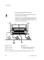
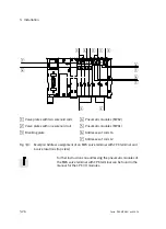
1
2
4
82/84
12/14
3/5
1
3/5
4
2
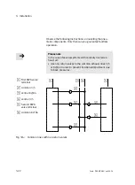
Fig.3/5:
Pneumatic connections on the MPA valve terminal
Tubing
Connection
identifier
(ISO 5599)
Connection
size
(ISO 228)
Connection
1)
Compressed air or
vacuum
1
G1/4"
Screw connector in the pneumatic inter
face, MP or MPM sub−base or supply
unit
Pilot air (external
auxiliary pilot air)
12/14
M7
Screw connector in the pneumatic inter
face, MP or MPM sub−base
Ducted exhaust
from the valves
3/5
QS10
Screw connector in exhaust plate
2
)
Ducted exhaust
from the pilot con
trol
82/84
M7
Screw connector in supply unit
2
Work air or vacuum
2 or 4
MPA1: M7
MPA2: G1/8"
Screw connector in the sub−base
1) Depending on what you have ordered, the MPA valve terminal may already be fitted with QS screw
connectors.
2) Only with MPA valve terminals with exhaust plate or supply unit
Table3/5:
Assignment of the connections
Summary of Contents for MPA-FB Series
Page 2: ......
Page 4: ...Contents and general instructions II Festo P BE MPA EN en 0502b...
Page 8: ...Contents and general instructions VI Festo P BE MPA EN en 0502b...
Page 17: ...Summary of components 1 1 Festo P BE MPA EN en 0502b Chapter 1...
Page 30: ...1 Summary of components 1 14 Festo P BE MPA EN en 0502b...
Page 31: ...Fitting 2 1 Festo P BE MPA EN en 0502b Chapter 2...
Page 47: ...Installation 3 1 Festo P BE MPA EN en 0502b Chapter 3...
Page 55: ...3 Installation 3 9 Festo P BE MPA EN en 0502b 1 2 3 Fig 3 2 Disconnecting the tubing...
Page 79: ...Commissioning 4 1 Festo P BE MPA EN en 0502b Chapter 4...
Page 96: ...4 Commissioning 4 18 Festo P BE MPA EN en 0502b...
Page 97: ...Diagnosis and error treatment 5 1 Festo P BE MPA EN en 0502b Chapter 5...
Page 139: ...Technical appendix A 1 Festo P BE MPA EN en 0502b Appendix A...
Page 151: ...Accessories B 1 Festo P BE MPA EN en 0502b Appendix B...
Page 161: ...Index C 1 Festo P BE MPA EN en 0502b Appendix C...
Page 162: ...C Index C 2 Festo P BE MPA EN en 0502b Contents C Index C 1...


