


UFS8000
Terminal Block / Electrical connection examples
112
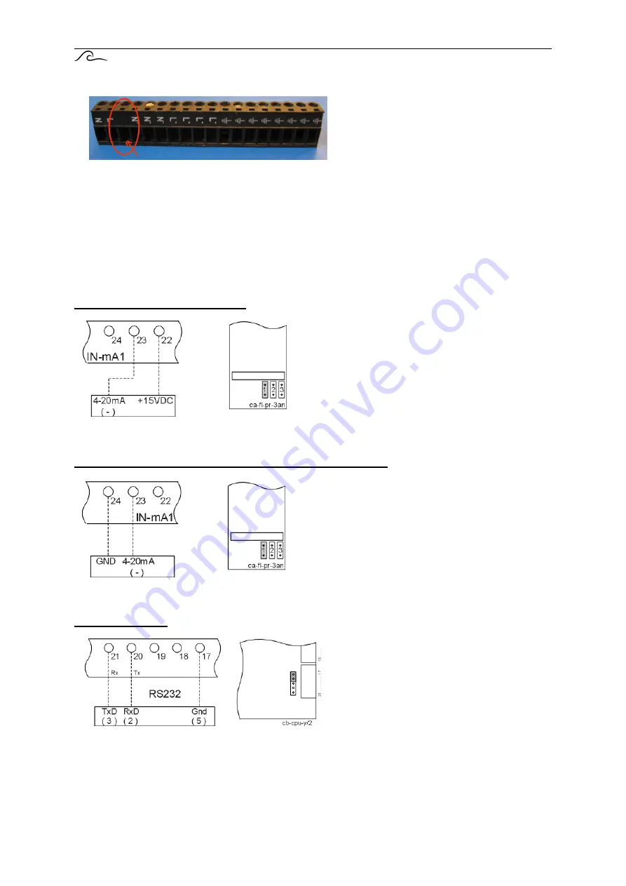
32.2. Remarks
The 3th terminal of the 18 pole black connector will not be used (see picture above).
33. Electrical connection examples
Attention!
When connecting components, it is recommended to completely disconnect the power supply from the
controller.
Connection of flow meter (2 wires)
Connection of a 2-wire flow meter with a 4 – 20mA
output to input IN-mA1.
A “jumper” should be placed on the “ca-fl-pr-3an”
PCB as shown in the illustration.
Jumpers “2” and “3” should be installed for IN-mA2
and IN-mA3, respectively.
Connection of flow meter powered by external supply (2 wires)
Connection of a 2-wire flow meter powered by
external supply with a 4 – 20mA output to input
IN-mA1.
A “jumper” should be placed on the “ca-fl-pr-3an”
PCB as shown in the illustration.
Jumpers “2” and “3” should be installed for IN-mA2
and IN-mA3, respectively.
RS232 Connection
To set the communication port of the
controller to “RS232”, the jumpers should be
installed (cpu PCB cb-cpu-y/2) according to
the illustration shown on the left.
Connector type DB9
Summary of Contents for UFS8000
Page 1: ...Controller for ultra filtration plants Operating manual Software version 1 06 UFS8000 ...
Page 7: ...40 Warranty conditions 122 ...
Page 11: ...UFS8000 Picture of front side 4 2 Picture of front side 1 LCD display touch panel ...
Page 115: ...UFS8000 Overview menu 108 30 Overview menu ...
Page 117: ...UFS8000 Terminal Block 110 32 Terminal block connection 32 1 Schematics ...
Page 118: ...UFS8000 Terminal Block 111 ...