17 - 16
To see Output Numbers and Status when connected to Panel initially, perform an Upload All, or for individual
Outputs, perform an Upload selected.
Output Set/Reset: Outputs can be Set/Reset by clicking on the Status box of the Output that you wish to Set/Reset,
then clicking the button on the Toolbar to set, and the button on the Toolbar to Reset.
Output Monitoring is also possible using the Monitor button, or Output Refresh using the Refresh button. Note
however that if the Output Monitor is active, you will not be able to modify anything on this screen.
Note:
On 3GS Version 4 panels the Output No. column is not displayed, as these numbers are fixed in 3GS Version 4
panels.
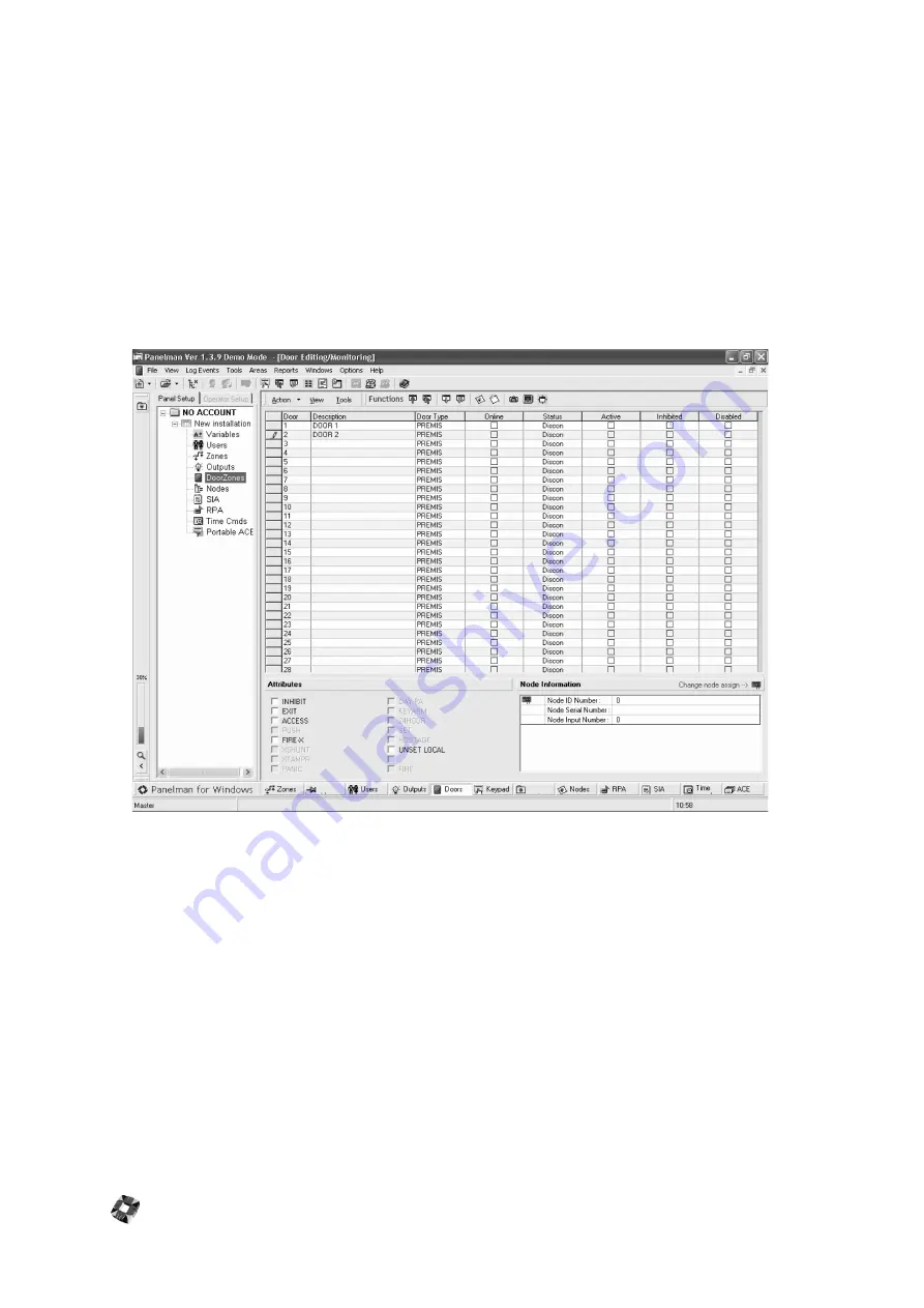
Door Editing/Monitoring Window
Like the Zone Editing Window, DoorZone Descriptions, Types and Attributes can be set up using this window. To
change a Door Type, click on the Door Type box of the Door that you wish to change and select the new Door type
from the drop-down list.
To change a Door Description, click on the description that you wish to change and flashing cursor will appear,
allowing you to edit/add text.
Use the function buttons to Upload or Download individual or all doors. These functions are also available by selecting
the zone and right-mouse clicking.
A check appears for the zone in the Online column to indicate that the zone is currently online. The Status column
shows the status of the zone: open, closed or discon. The Active column indicates whether the zone is active in the
current panel mode i.e set or unset, while the Inhibits and Disabled columns show if this zone is inhibited or disabled.
Door Monitoring is also possible using the Monitor button, or DoorZone Refresh using the Refresh button.
Note however that if the DoorZone Monitor is active, you will not be able to modify anything on this screen.
Node Information
This pane gives the user information about the node where the door is assigned, and also gives the node ID number,
serial number and input number.
Summary of Contents for 3GS
Page 4: ...Introduction iv...
Page 12: ...Introduction 8...
Page 14: ...1...
Page 18: ...System Overview 1 6...
Page 20: ......
Page 26: ......
Page 34: ......
Page 38: ...Intelligent PSUs 4 6...
Page 40: ......
Page 97: ...Issue 4 5 August 2005 Nodes 5 59...
Page 98: ...Issue 4 5 August 2005 Nodes 5 61...
Page 100: ......
Page 106: ...3GS Technical Manual...
Page 116: ...3GS Technical Manual 7 12 Programming Overview Issue 4 5 August 2005 3GS Initial Setup Menu...
Page 118: ...3GS Technical Manual...
Page 146: ...3GS Technical Manual Issue 4 5 August 2005 Programming Menus 8 31 Node Configure Inputs Menu...
Page 153: ...3GS Technical Manual Issue 4 5 August 2005 8 38 Programming Menus Service Mode Test Menu...
Page 155: ...3GS Technical Manual Issue 4 5 August 2005 8 40 Programming Menus Service Mode Monitor Menu...
Page 217: ...3GS Technical Manual Issue 4 5 August 2005 8 108 Programming Menus...
Page 218: ...3GS Technical Manual Issue 4 5 August 2005 Programming Menus 8 109...
Page 220: ......
Page 222: ...3GS Version 5 User Guide 9 5 3GS SYSTEM KEYPAD DISPLAY...
Page 254: ...3GS Version 5 User Guide 9 37 Some examples of Alert Messages...
Page 264: ......
Page 265: ...I n t h i s c h a p t e r HHT Overview 10 3 Main Menu 10 5 HAND HELD TERMINAL HHT 10...
Page 266: ......
Page 280: ......
Page 288: ......
Page 290: ......
Page 293: ...Issue 4 5 August 2005 DM1200 Digital Communicator Modem 12 5...
Page 302: ......
Page 304: ...Network Router 13 4 SAMPLE CONNECTION DIAGRAM SCENARIOS...
Page 308: ...Network Router 13 8...
Page 310: ......
Page 318: ......
Page 338: ...Issue 4 5 August 2005 Technical Specifications 15 23...
Page 340: ...1...
Page 346: ......
Page 366: ...17 22...
Page 367: ...I n t h i s c h a p t e r Introduction to CiTeC II 18 3 CITEC II INSTALLATION 18...
Page 368: ......
Page 370: ...CiTeC II Installation 18 4...
Page 377: ...Issue 4 5 August 2005 19 7...
Page 378: ...19 8...
Page 385: ......
Page 386: ......


