Issue 4.5 August 2005
Europlex Universal Interface Card (EUIC) 11-6
C
ONNECTING
THE
EUIC
TO
THE
V
IDEO
M
ULTIPLEXER
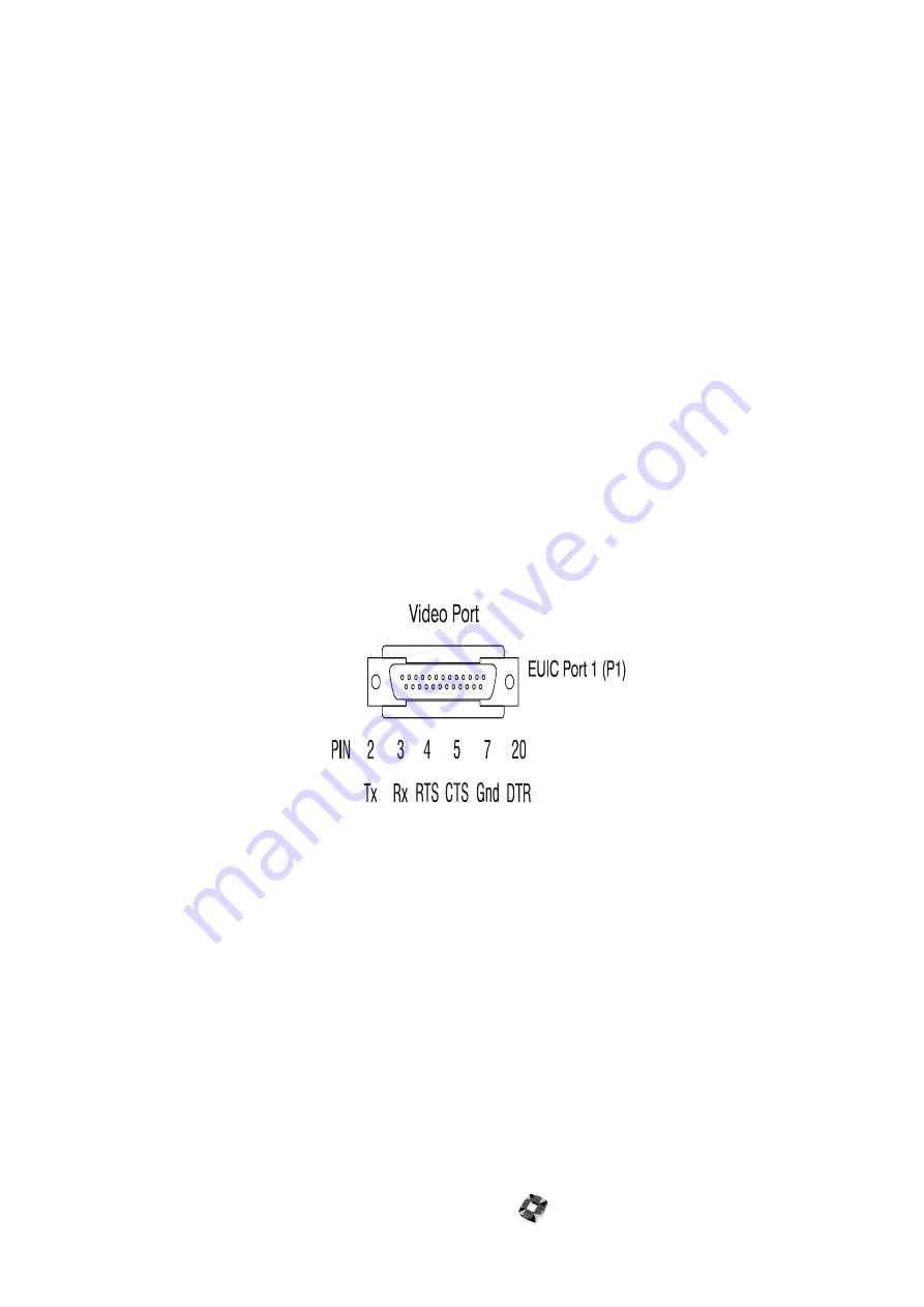
To connect the EUIC to the video multiplexer
1
Use a cable as specified in the video multiplexer manual with a 25-way female termination on the EUIC end.
2
Insert the female end into port 1(P1) on the EUIC.
3
Start the EUIC programming software package.
4
Open the comms port on the PC.
5
Ensure that the communications settings of the EUIC host port match the settings specified for the video multiplexer
– otherwise no communications will take place between the EUIC and the video multiplexer. Remember to change
the PC settings to match these.
6
Select Video Options in the Communications menu and choose the option for the multiplexer connected to port 1.
7
Press Reset on the EUIC as requested, to save the video selection to the battery backed memory.
8
The EUIC software version and current settings are displayed on the PC if communications are properly setup.
9
When an alarm command is executed by the EUIC, it will transmit the set alarm channel command using the
appropriate protocol to port 1. This can be observed by a brief flash on LED 2.
10
When the event is false and the alarm has to be cleared again, the EUIC will transmit the clear alarm channel. These
transmissions will activate and clear the alarm channels on the video multiplexer. If this is not the case, then it is
likely that either the comms port is not correctly connected or the settings are incorrect. Check the connections and
retry.
11
If this does not resolve the problem, then you can connect the Default Link to reset the EUIC comms settings for all
the ports to the default settings. For further information, see “Default Setup” on page 11-9.
Alternately try all the different PC communications settings until the correct setting for the EUIC is chosen.
Summary of Contents for 3GS
Page 4: ...Introduction iv...
Page 12: ...Introduction 8...
Page 14: ...1...
Page 18: ...System Overview 1 6...
Page 20: ......
Page 26: ......
Page 34: ......
Page 38: ...Intelligent PSUs 4 6...
Page 40: ......
Page 97: ...Issue 4 5 August 2005 Nodes 5 59...
Page 98: ...Issue 4 5 August 2005 Nodes 5 61...
Page 100: ......
Page 106: ...3GS Technical Manual...
Page 116: ...3GS Technical Manual 7 12 Programming Overview Issue 4 5 August 2005 3GS Initial Setup Menu...
Page 118: ...3GS Technical Manual...
Page 146: ...3GS Technical Manual Issue 4 5 August 2005 Programming Menus 8 31 Node Configure Inputs Menu...
Page 153: ...3GS Technical Manual Issue 4 5 August 2005 8 38 Programming Menus Service Mode Test Menu...
Page 155: ...3GS Technical Manual Issue 4 5 August 2005 8 40 Programming Menus Service Mode Monitor Menu...
Page 217: ...3GS Technical Manual Issue 4 5 August 2005 8 108 Programming Menus...
Page 218: ...3GS Technical Manual Issue 4 5 August 2005 Programming Menus 8 109...
Page 220: ......
Page 222: ...3GS Version 5 User Guide 9 5 3GS SYSTEM KEYPAD DISPLAY...
Page 254: ...3GS Version 5 User Guide 9 37 Some examples of Alert Messages...
Page 264: ......
Page 265: ...I n t h i s c h a p t e r HHT Overview 10 3 Main Menu 10 5 HAND HELD TERMINAL HHT 10...
Page 266: ......
Page 280: ......
Page 288: ......
Page 290: ......
Page 293: ...Issue 4 5 August 2005 DM1200 Digital Communicator Modem 12 5...
Page 302: ......
Page 304: ...Network Router 13 4 SAMPLE CONNECTION DIAGRAM SCENARIOS...
Page 308: ...Network Router 13 8...
Page 310: ......
Page 318: ......
Page 338: ...Issue 4 5 August 2005 Technical Specifications 15 23...
Page 340: ...1...
Page 346: ......
Page 366: ...17 22...
Page 367: ...I n t h i s c h a p t e r Introduction to CiTeC II 18 3 CITEC II INSTALLATION 18...
Page 368: ......
Page 370: ...CiTeC II Installation 18 4...
Page 377: ...Issue 4 5 August 2005 19 7...
Page 378: ...19 8...
Page 385: ......
Page 386: ......


