9-16
C
ODED
R
ESET
Under normal conditions, the system can only be re-armed (after an alarm activation) following a service/installation
company visit.
When an alarm has occurred the display will show a CALL SERVICE message and the user will not be able to re-arm the
system.
When enabled, the Coded Reset option allows you to re-arm the system, avoiding the need to call an installer to the
site.
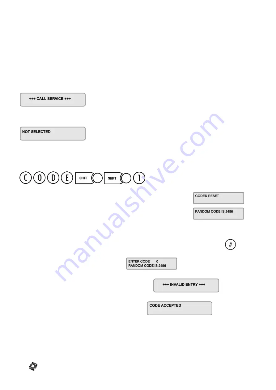
When you have acknowledged an alarm, the keypad will continue to display the message:
If you attempt to re-arm the system, the keypad will beep, and then briefly display the message:
You should now contact the Security Control Station for a release code. If the Security Control Station is unable to give
you a release code, contact your installer.
User Reset Procedure
Select Coded Reset.
The display will show a random 4-digit number for standard system and a 6-digit
number for Class IV.
Contact the Control Security Station with this random number.
The Central Station operator then converts this number to a 4-digit (6 digit) return code acceptable to the system.
When you receive your return code from the Central Station operator, return to the keypad, and press the
key.
The display will prompt you to enter the return code:
Key it in at the prompt. If the code is incorrect, the display will show:
When you have keyed in the correct code, the display will show:
You can now re-arm the system by selecting Full Set.
Note
All users who have the FULL SET option will automatically be assigned the Coded Reset option
[See page
19: User Setup]
.
Summary of Contents for 3GS
Page 4: ...Introduction iv...
Page 12: ...Introduction 8...
Page 14: ...1...
Page 18: ...System Overview 1 6...
Page 20: ......
Page 26: ......
Page 34: ......
Page 38: ...Intelligent PSUs 4 6...
Page 40: ......
Page 97: ...Issue 4 5 August 2005 Nodes 5 59...
Page 98: ...Issue 4 5 August 2005 Nodes 5 61...
Page 100: ......
Page 106: ...3GS Technical Manual...
Page 116: ...3GS Technical Manual 7 12 Programming Overview Issue 4 5 August 2005 3GS Initial Setup Menu...
Page 118: ...3GS Technical Manual...
Page 146: ...3GS Technical Manual Issue 4 5 August 2005 Programming Menus 8 31 Node Configure Inputs Menu...
Page 153: ...3GS Technical Manual Issue 4 5 August 2005 8 38 Programming Menus Service Mode Test Menu...
Page 155: ...3GS Technical Manual Issue 4 5 August 2005 8 40 Programming Menus Service Mode Monitor Menu...
Page 217: ...3GS Technical Manual Issue 4 5 August 2005 8 108 Programming Menus...
Page 218: ...3GS Technical Manual Issue 4 5 August 2005 Programming Menus 8 109...
Page 220: ......
Page 222: ...3GS Version 5 User Guide 9 5 3GS SYSTEM KEYPAD DISPLAY...
Page 254: ...3GS Version 5 User Guide 9 37 Some examples of Alert Messages...
Page 264: ......
Page 265: ...I n t h i s c h a p t e r HHT Overview 10 3 Main Menu 10 5 HAND HELD TERMINAL HHT 10...
Page 266: ......
Page 280: ......
Page 288: ......
Page 290: ......
Page 293: ...Issue 4 5 August 2005 DM1200 Digital Communicator Modem 12 5...
Page 302: ......
Page 304: ...Network Router 13 4 SAMPLE CONNECTION DIAGRAM SCENARIOS...
Page 308: ...Network Router 13 8...
Page 310: ......
Page 318: ......
Page 338: ...Issue 4 5 August 2005 Technical Specifications 15 23...
Page 340: ...1...
Page 346: ......
Page 366: ...17 22...
Page 367: ...I n t h i s c h a p t e r Introduction to CiTeC II 18 3 CITEC II INSTALLATION 18...
Page 368: ......
Page 370: ...CiTeC II Installation 18 4...
Page 377: ...Issue 4 5 August 2005 19 7...
Page 378: ...19 8...
Page 385: ......
Page 386: ......


