4
.
D
a
t
a
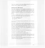
transfer must be carried out by observing the ACKN
LG or
BU
SY s
i
g
nal
.
(Data transfer to this printer can be ca
rr
i
ed out
o
n
ly a
f
ter
receipt of the ACKNLG signal or when the l
eve
l
of the
B
USY sig
nal is LOW.)
5.
U
nder
n
o
rmal conditions
,
printer cable pins 11
,
12
,
and
32 are
activate
d
w
hen the paper-end condition is detected. Th
e <ESC>
8 code dis
ables pins 11 and 32
,
but not pin 12. Those com
p
u
ters
that moni
tor pin 12 halt printing when the paper is out
,
m
aking
<ESC> 8
ineffective
.
I
nt
e
r
f
a
ce
timing
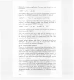
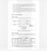
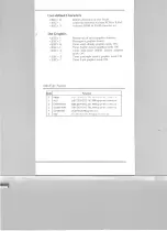
Figure I
-
I sho
ws the timing for th
e
parallel interface
.
DA
TA
S
T
ROBE
BUSY
A
CKNL
G
0.5
J1S
Imin.)
0.5
J1S
Imin
.
l
0.5
J1S
Imin.)
Approx. 5
J
1S
Approx. 7
J
1S
S
i
g
n
a
l
re
l
a
tionships
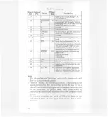
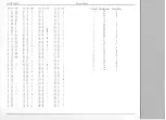
Tab
l
e 1-2 s
h
o
ws the way data entry is handled in the on-l
ine and
off-
li
ne states
by showing the relationships between sev
e
n
sign
a
l
sets
.
On-Line
SLCTIN
ERROR
BUSY
ACKNLG
DATA ENTR
Y
OFF
HI
G
H
/
LOW LOW
HIGH
Not generated
Disabled
ON
HI
G
H
HIGH
LOW
/
HIGH Generated after data entry
Enabled
'
ON
L
O
W
HIGH
Same
Same
Enabled (norm
a
l entr
y)
*Whe
n
S
L
C
T IN is at high level, data entry is enabled, but th
e input
da
t
a wi
ll
be
disregarded until SLCT IN is at low level
.
Note
:
ERROR status is assumed to rest only in off-line st
a
t
e, and
the E
RROR status does not always mean SLCT IN.
Summary of Contents for LX-80
Page 1: ...LX 80 Printer P8492037 0 Y560991020 ...
Page 2: ...EPSON LX SOPRINTER Operating Manual ...
Page 8: ...The Parallel Interface Data Transfer Sequence Interface timing Signal relationships ...
Page 11: ......
Page 41: ......
Page 67: ......
Page 85: ......
Page 103: ......
Page 111: ......
Page 145: ......
Page 171: ......
Page 173: ......
Page 177: ......
Page 181: ......
Page 189: ......
Page 190: ......

