background image

EPSON EPL-N3000/AcuLaser M4000N

Revision C

Operating Principles     

Functions of Major Components

50

Confidential

ROS ASSY

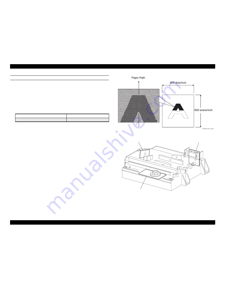
The ROS (Raster Output Scanner) scans the surface of the drum with a laser beam. The 
ROS ASSY consists of the following three major components, namely, LD (Laser 
Diode) Assembly, Scanner Assembly and SOS PWB:

†

LD Assembly:


The LD Assembly generates a laser beam. The generated beam is turned ON/OFF 
according to the printing data signal. The nominal maximum output of the 
semiconductor laser diode used as the light source of the laser is as indicated 
below.

†

Scanner Assembly: 


Consists of the Polygon Mirror with 12 mirror facets and the Scanner Motor. 


The Polygon Mirror is secured to the shaft of the Scanner Motor.


The Scanner Motor rotates the Polygon Mirror at a certain speed. The spinning 
Polygon Mirror reflects the beam, via lenses and mirrors, onto the surface of the 
rotating drum and the beam scans the drum surface from one side to the other. 
One-line scanning is carried out by one mirror facet.


The Scanner Motor is driven by three-phase full-wave current linear drive. The 
current in the coil for each phase is switched by the Hall amplifier matrix, and the 
signal from the phase detection terminal of the Motor is used.

†

SOS PWB:


The laser beam that has entered the SOS Sensor of the SOS PWB is converted to 
an electric signal (SOS signal) and detects the initial position for each line 
scanning.

A latent image for one line is created when the laser beam is turned on and off and 
scans the drum surface from its one side to the other. A image for one plane is created 
when scanning by the laser beam is repeated on the rotating drum. The resolution in the 
scanning direction (from right to left) depends on the revolving speed of the Scanner 
Motor and the quickness of adjustment of laser. The resolution in the process direction 
(from top to bottom) depends on the revolving speed of the Scanner Motor (The faster 
the scanning is performed, the earlier the scanning of the next line is started).

Figure 2-27.  Conceptual Diagram of Image Creation by Scanning

Figure 2-28.  Major Components of the ROS ASSY

600 dpi mode

1200 dpi mode

10 mW

10 mW

LD Assembly

JG6121AA

SOS PWB

Scanner Assembly

Summary of Contents for AcuLaser M4000N

Page 1: ...EPSON EPL N3000 AcuLaserM4000N A4 Monochrome Laser Printer SERVICE MANUAL SEPG03004 Confidential ...

Page 2: ...ge without notice All effort have been made to ensure the accuracy of the contents of this manual However should any errors be detected SEIKO EPSON would greatly appreciate being informed of them The above not withstanding SEIKO EPSON CORPORATION can assume no responsibility for any errors in this manual or the consequences thereof EPSON is a registered trademark of SEIKO EPSON CORPORATION General...

Page 3: ...ION IN WORKING ON POWER SUPPLY AND OTHER ELECTRONIC COMPONENTS 4 WHEN DISASSEMBLING OR ASSEMBLING THE PRODUCT MAKE SURE TO WEAR GLOVES TO AVOID INJURY FROM METAL PARTS WITH SHARP EDGES WARNING 1 REPAIRS ON EPSON PRODUCT SHOULD BE PERFORMED ONLY BY AN EPSON CERTIFIED REPAIR TECHNICIAN 2 MAKE CERTAIN THAT THE SOURCE VOLTAGES IS THE SAME AS THE RATED VOLTAGE LISTED ON THE SERIAL NUMBER RATING PLATE I...

Page 4: ...icing the product APPENDIX Provides the following additional information for reference Connectors Wiring Diagrams and Signal Information Control Panel Special Operations Firmware Update Information Sheet Exploded Diagrams ASP List Parts List Symbols Used in this Manual Various symbols are used throughout this manual either to provide additional information on a specific topic or to warn of possibl...

Page 5: ... I F Interface I L Interlock ID Image Density or Identification L Left L H Left Hand L P Low Paper LD Laser Diode LEF Long Edge Feed LVPS Low Voltage Power Supply MAG Magnetic MCU Machine Control Unit MOT Motor N P No Paper NVM Non Volatile Memory OCT Offset Catch Tray OHP Overhead Projector In this manual OHP means OHP film OPT Optional Paper Tray P H Paper Handling P R Pressure Roll Pixel Pictur...

Page 6: ...e switch off the printer power and unplug the power cord from the wall outlet If you must service the printer when the power is applied be aware of the potential for electrical shock and do all tasks by following the procedures in this manual Mechanical Components If you service a driving assembly e g gears first turn off the power and unplug the power cord Then manually rotate the assembly W A R ...

Page 7: ...emitted unexpectedly during a maintenance operation Never disassemble any part or open any cover to which a warning label about laser beam is affixed If you disassemble or assemble the printer turn off the power If you need to work on the printer with power applied strictly follow the instructions in this manual Understand how the laser beam functions and take maximum precautions not to injure you...

Page 8: ...mall amount of ozone that never exceeds the safety permissible value 0 1 ppm 0 2 mg m3 in the normal work environment Avoid operating the printer under any of the following conditions Any ambient conditions other than specified for use of this printer Use of two or more laser printers in a small room Use in a place where sufficient ventilation is not available Especially continuous operation for a...

Page 9: ...or injure yourself Dry your hands first When pulling out a part including a harness do not use too much force Pull out the part carefully and slowly step by step Consumables Understand the following explanation and handle the consumables carefully Some parts may cause a particulate explosion or fire if handled improperly Do not handle these parts near fire or throw into a fire Some materials espec...

Page 10: ...Option OCT PWBA OCT HVPS MCU LDD ROS ASSY INTERLOCK S W 5V INTERLOCK S W 24V INTERLOCK S W REAR HVPS Circuit PWBA EXIT MOTOR MOTOR ASSY EXIT MAIN MOTOR HEAT ON Short FAN ALARM FAN ALARM HEAT ON Long 24VDC AFT 24VDC AFT 24VDC AFT A B A B 24VDC AFT FAN MAIN FAN SUB Heater Rod Long Heater Rod Short JG6126EA SWITCH DUPLEX SW REAR COVER SWITCH I L ASSY INTERLOCK BEF Interlock S W 5VR TEMP POWER SWITCH ...

Page 11: ...IN MOTOR HEAT ON Short FAN MAIN ALARM HEAT ON Long 24VDC AFT 24VDC AFT 24VDC AFT A B A B 24VDC AFT FAN MAIN FAN SUB Heater Rod Long Heater Rod Short J26126EA SWITCH DUPLEX SW REAR COVER POWER SWITCH Low Voltage Generation FUSER ASSY Power Save Control POWER SAVE 1 POWER SAVE 2 FAN SUB ALARM MAIN MOTOR Control MAIN MOTOR ON MAIN MOTOR ALM EXIT MOTOR Control CRU A CRU B INA INB INA INB SCANNER MOTOR...

Page 12: ...tial Revision Status Revision Date of Issue Description A Oct 31 2003 First Release B Nov 21 2003 Full fledged revision C Feb 29 2008 Revised Contents All chapters Information on AcuLaser M4000N has been added ...

Page 13: ...2 2 5 7 DRIVE 53 2 5 8 ELECTRICAL 54 2 5 9 OPTION FEEDER 55 2 5 10 DUPLEX 56 2 5 11 OCT 57 2 6 Control 59 2 6 1 Paper Size Control 59 2 6 2 ROS Control 59 2 6 3 Fuser Control 60 2 7 Operating Principles of Electric Circuitry 61 2 7 1 Operation Overview of the Main Control Circuit Board 61 Chapter 3 Troubleshooting 3 1 Overview 64 3 1 1 Specified Tools 64 3 1 2 Procedure for Troubleshooting 64 3 1 ...

Page 14: ...EPROM Error 102 3 2 46 Engine Initialization Error 102 3 2 47 Other Hardware Error 103 3 2 48 Software Error 103 3 3 Troubleshooting for Faulty Operation 104 3 3 1 Power Does Not Turn ON 104 3 3 2 LCD LED Malfunction 107 3 3 3 Keypad Operation Impossible 107 3 3 4 Other Printer Operation Fault 108 3 3 5 Face Up Tray Error 108 3 3 6 Full Stack Error 500 Paper Exit 109 3 4 Troubleshooting for Indivi...

Page 15: ...ecautions 161 4 1 2 Precautions in Performing Work 162 4 1 3 Disassembly and Reassembly Procedure 163 4 1 4 Difference between EPL N3000 and AcuLaser M4000N in Disassembly Assembly 164 4 2 Cover 167 4 2 1 COVER REAR 167 4 2 2 COVER RIGHT 168 4 2 3 COVER LEFT 169 4 2 4 COVER TOP CONTROL PANEL 170 4 2 5 COVER FRONT 172 4 2 6 SWITCH I L ASSY 173 4 3 150 Paper Cassette 175 4 3 1 ROLL ASSY RETARD 175 4...

Page 16: ...SENSOR FACE UP OPEN 267 4 8 7 SENSOR FULL STACK 268 4 8 8 ACTUATOR FULL STACK 269 4 8 9 COVER REAR 500 270 4 8 10 ROLL FU 271 4 8 11 LEVER GATE HOLDER SPRING LEVER GATE LEVER GATE FU 272 4 8 12 LEVER LATCH LEFT SPRING LATCH FU LEVER LATCH RIGHT 273 4 8 13 ROLL PINCH FU SPRING PINCH FU 274 4 8 14 GATE FU 275 4 8 15 GATE ASSY EXIT 276 4 9 Frame Drive 277 4 9 1 MOTOR COVER 277 4 9 2 MAIN MOTOR 279 4 ...

Page 17: ...NESS ASSY DUP 359 4 13 Option OCT 360 4 13 1 Option OCT 360 4 13 2 COVER REAR 362 4 13 3 TRAY ASSY OCT 363 4 13 4 COVER OCT 364 4 13 5 COVER FRONT 366 4 13 6 ACTUATOR FULL STACK 367 4 13 7 PWBA OCT 368 4 13 8 MOTOR ASSY OFFSET 370 4 13 9 SOLENOID ASSY GATE 371 4 13 10 SENSOR OCT 372 4 13 11 ROLL OCT LOWER 374 4 13 12 ROLL OCT UPPER 376 4 13 13 MOTOR ASSY OCT 378 4 14 AcuLaser M4000N Unique Disasse...

Page 18: ...on Wiring Diagrams 413 7 2 2 Overall Connection Wiring Diagram 415 7 2 3 Wiring and Signal Descriptions between Components 418 7 3 Control Panel Special Operations 428 7 3 1 Operation Method Functions 428 7 3 2 Special Menu 429 7 4 Information Sheet 430 7 4 1 Status Sheet 430 7 4 2 Network Status Sheet AcuLaser M4000N only 432 7 4 3 Engine Status Sheet AcuLaser M4000N only 434 7 4 4 Print Log Repo...

Page 19: ...Confidential C H A P T E R 1 PRODUCTDESCRIPTION ...

Page 20: ...thernet Type B slot option Printer Language PostScripts 3 PCL6 LJ4 GL2 ESC P2 FX I239X ESC Page ESC Page B W FX ESCP2 I239X PCL5e PCL6 PostScript 3 PDF 1 3 Dimensions Main unit 428 x 468 x 404 mm 428 x 480 x 404 mm Weight Main unit 20 9 Kg 21 5 Kg Power supply AC120 V 50 60 Hz AC220 V 240 V 50 60 Hz AC120 V 50 60 Hz AC220 V 240 V 50 60 Hz Power consumption 100V 110V 220 240V Max 110 V 945 W 220 V ...

Page 21: ...ard lower paper cassette 3 locking clip 9 power switch 4 control panel 10 paper support 5 right side cover 11 cover A 6 paper indicator 12 imaging cartridge 1 2 3 4 5 6 7 8 9 10 11 12 Table 1 2 Names of Parts No Name No Name 1 cover B 6 parallel interface connector 2 upper option cover 7 Ethernet interface connector 3 face up tray 8 Type B interface card slot cover 4 AC inlet 9 paper path lever 5 ...

Page 22: ...L N3000 AcuLaser M4000N Revision C Product Description Product Specifications 22 Confidential Figure 1 3 Option Table 1 3 Names of Parts No Name No Name 1 Duplex Unit 3 550 Sheet Cassette A4 Unit 2 OCT 1 2 3 3 ...

Page 23: ...W No 1 No 2 No 5 No 3 No 6 No 4 No 7 H D Table 1 4 Dimensions and Weight List NO Configuration W D H Weight 1 Main unit 428 mm 468 mm 480 mm 404 mm 20 9 kg 21 5 kg 2 Main unit Duplex unit 428 mm 540 mm 572 mm 404 mm 22 8 kg 23 4 kg 3 Main unit 550 sheet unit 1 level 428 mm 468 mm 480 mm 499 mm 27 2 kg 27 8 kg 4 Main unit 550 sheet unit 2 levels 428 mm 468 mm 480 mm 589 mm 33 5 kg 34 1 kg 5 Main un...

Page 24: ...al INSTALLATION SPACE REQUIREMENTS The following figure shows the dimensions of the space required around the printer Be sure to provide the space for installation operation and maintenance Figure 1 5 Installation Space Requirements NOTE Dimensions in parenthesis are with the paper cassette extended ...

Page 25: ...er M4000N 64 105 g m2 Transparency sheets A4 Letter 100 sheets Label A4 Letter 100 sheets Envelope C5 C6 Com 10 DL Monarch ISO B5 15 20 sheets Thick paper A4 A5 B5 F4 LT HLT LGL EXE GLG GLT Paper width 76 2 215 9 mm Paper length 127 0 355 6 mm 60 sheets 106 216 g m2 Cassette C1 Standard paper Plain paper Recycled paper A4 A5 B5 F4 LT HLT LGL EXE GLG GLT 550 sheets 64 105 g m2 Transparency sheets A...

Page 26: ...r torn paper Irregularly shaped paper or paper with non perpendicular corners Labels that peel off easily Paper with glue staples or paper clips attached to it Ink jet paper for special applications super fine glossy glossy film etc Paper previously used in a thermal or ink jet printer Transparencies for other color laser printers or color photocopiers Sheets already printed on other color monochr...

Page 27: ...st to print at a smaller size than the paper Guaranteed print area All areas except 4 0 mm from each edge of paper Table 1 6 Guaranteed Print Area ENVELOPE ORIENTATION POSTCARD ORIENTATION 4 0 mm 4 0 mm 4 0 mm 4 0 mm Envelope Size DL C6 Com10 Monarch C5 ISO B5 MP cassette Cassette 1 2 and 3 Feeding Direction Postcard type Postcard Front side printing Postcard Reverse side printing Feeding Directio...

Page 28: ... Included with main unit of AcuLaser M4000N is 7 500 cartridge Note Maintenance unit is composed of the following parts EBTR Assy EKIT ROLL ASSY FEED x 2 sets For MP tray and Cassette 1 Paper eject Capacity Face down 500 sheets Face up 70 sheets Offset catch tray 500 sheets Part name Capacity EPL N3000 AcuLaser M4000N Imaging cartridge 6 000 pages 1 17 000pages 7 500 pages 2 20 000pages Fuser unit...

Page 29: ...e program Control panel 6 switches 3 LEDs and 20 digits X 1 STN LCD with white backlight 7 buttons LCD 22 characters 5 lines and 3 LEDs Printer language PostScripts 3 PCL6 LJ4 GL2 ESC P2 FX I239X ESC Page ESC Page B W FX ESCP2 I239X PCL5e PCL6 Adobe PostScript 3 PDF 1 3 Auxiliary software DIAG mode Status Sheet USB Ext I F StatusSheet Reserve Job List Form Overlay List Network Status Sheet AUX Sta...

Page 30: ... Status ROM CHECK X O O RAM CHECK X O O HDD CHECK X O O Unable Clear Error O O O SELF TEST X O O Reset All All blinking O O Reset X O O Cancel All Print Job X O O Cancel Print Job by panel X O O Writing ROM P X O O Reset to Save X O O Form Feed X O O Status Sheet X O O Print Log Report X X O Reserve Job List X X O Form Overlay List X X O Status ESC Page Font Sample PCL Font Sample ESCP2 Font Sampl...

Page 31: ...ntenance unit Needed Soon X X O Feed Roller C2 Needed Soon X X O Feed Roller C3 Needed Soon X X O Non Genuine Toner Cartridge X O O Table 1 7 List of Printer Messages Sort Printer Status LEDs status LCD status Error EPL N3000 AcuLaser M4000N Error Service Req Cffff 2 All blinking O O Service Req Eggg 2 All blinking O O Optional RAM Error O O O Write Error ROM P O X O Cassette Error yyy yyy 003 O X...

Page 32: ...cates the Paper Source setting except for Auto of the control panel 7 uuu indicates the paper size setting in the Tray Menu of the control panel Error Non Genuine Toner Cartridge O O O Toner Cart Error O X O Replace Fuser Δ2 X O Replace Maintenance Unit Δ2 X O Replace Feed Roller C2 Δ2 O O Replace Feed Roller C3 Δ2 O O wwww 3 Open O O O Manual Feed sss 5 Δ2 O O Can t Print Duplex Δ3 O O Face up Pa...

Page 33: ...Confidential C H A P T E R 2 OPERATINGPRINCIPLES ...

Page 34: ... the drum onto the paper 5 Separation The paper is separated from the surface of the drum by partial neutralization of the charge on the paper 6 Fusing The toner image is fused to the paper by application of heat and pressure 7 Cleaning Residual toner is removed from the surface of the drum As the drum turns the surface of the drum passes the steps of charging exposure development transfer separat...

Page 35: ...ectron hole pairs inside the photoconductive layer Electrons attracted by the electric field move toward the inner metal portion of the drum and flow in there Holes move toward the external surface of the photoconductive layer thus reducing negative charges there The areas of the lower negative charge level form the latent print image In the next process toner is attracted to the electrostatic lat...

Page 36: ...e but varies with the coverage range of the image and ambient conditions such as temperature and humidity Toner used once cannot be reused At the starting point of each printing process the whole surface of the drum is scanned with laser beam and the charge from the previous printing process If any charge remains on the surface of the drum from the previous step it will be removed completely At th...

Page 37: ...ansmits one line of rasterized bit image data to the MCU of the HVPS MCU The VDO signal carrying the image data is converted to the LVDS signal at the MCU of the HVPS MCU and transmitted to the ROS ASSY as the P DATA and P DATA signals On the ROS ASSY the received signal is converted to a very thin laser beam which is turned on or off according to the video signal The laser beam once reflected by ...

Page 38: ...ASSY and FUSER ASSY The driving force transmitted to the 150 FEEDER ASSY drives the ROLL REGI METAL and ROLL REGI RUBBER and the ROLL ASSY NUDGER and ROLL ASSY FEED The driving force transmitted to the 550 FEEDER ASSY drives the ROLL ASSY NUDGER and ROLL ASSY FEED The driving force transmitted to the EP Cartridge drives the Drum and is transmitted via the Drum Gear to the BTR ASSY The driving forc...

Page 39: ...gure 2 8 Driving Force Transmission Route for Imaging Cartridge Figure 2 9 Driving Force Transmission Route for FEEDER ASSY Gear 3 Gear 2 MAIN MOTOR JG6110AA IMAGING CARTRIDGE Gear 16 Gear 13 Gear 14 Gear 5 CLUTCH ASSY PH GEAR IDLER NUDGER GEAR NUDGER MAIN MOTOR JG6108AA 250 550 FEEDER ASSY 150 FEEDER ASSY Gear 15 CLUTCH ONEWAY NUDGER ...

Page 40: ...ute 40 Confidential Figure 2 10 Driving Force Transmission Route for CLUTCH REGI Figure 2 11 Driving Force Transmission Route for FUSER ASSY Gear 18 CLUTCH REGI Gear 17 Gear 13 Gear 14 Gear 5 Gear 15 MAIN MOTOR JG6109AA Gear HR GEAR 9 Gear 6 Gear 7 Gear 8 Gear 5 MAIN MOTOR JG6111AA FUSER ASSY ...

Page 41: ...riving force for the OPTION FEEDER is generated by the MOTOR FEEDER The force is transmitted to the OPTION FEEDER components that require mechanical driving force as shown in Figure 2 14 and Figure 2 13 below Figure 2 13 Driving Force of Motor Feeder 2 3 2 2 Gear Layout Figure 2 14 Driving Force Transmission Route for OPTION FEEDER GEAR 16 49 GEAR 25 2 MOTOR ASSY EXIT GEAR21 JG6112AA 500 Paper Exi...

Page 42: ...ute for Duplex Unit 2 3 4 OCT 2 3 4 1 Motor Assy OCT The driving force for the OPTION OCT is generated by the MOTOR ASSY OCT The force is transmitted to the OPTION OCT components that require mechanical driving force as shown in Figure 2 18 and Figure 2 17 below Figure 2 17 Driving Force of Motor Assy OCT 2 3 4 2 Gear Layout Figure 2 18 Driving Force Transmission Route for OCT MOTOR DUPLEX GEAR ID...

Page 43: ...ating Principles Paper Transport 43 Confidential 2 4 Paper Transport The paper is fed from the Tray1 Tray2 Tray3 or Tray4 and is transported along the paper path in the printer as shown in Figure 2 19 2 4 1 Paper Feeding Route Figure 2 19 Paper Path ...

Page 44: ...r Transport Engine only Figure 2 21 Major Components Related to Paper Transport with OPTION DUPLEX OPTION 550 FEEDER OPTION OCT 500 PAPER EXIT FACE UP TRAY installed Pressure Roll Heat Roll FUSER ASSY Drum BTR ASSY JG6114AA ROLL ASSY FEED ROLL ASSY RETARD ROLL ASSY NUDGER ROLL REGI METAL ROLL REGI RUBBER ROLL EXIT ROLL PINCH EXIT ROLL ASSY FEED ROLL ASSY RETARD ROLL ASSY NUDGER ROLL ASSY TURN ROLL...

Page 45: ...es Standard Face down tray Paper output full Automatic detection using sensor Paper output destination Switched manually using the lever Face up Full Paper output destination Switched manually using the lever If the face up tray is chosen the delivery to duplex printing and OCT will not be made EP Cartridge Presence of cartridge Automatic detection using CSIC Presence of new cartridge IC chip dete...

Page 46: ...to retain the paper in the predetermined position in the lateral direction The GUIDE ASSY SD L150 moves in synchronization with the GUIDE ASSY SD R150 LOCK EXTENSION The 150 PAPER CASSETTE can be adjusted to the paper length in its feed direction by changing the position of the HOUSING EXTENSION150 back and forth The LOCK EXTENSION fastens the HOUSING EXTENSION150 to a proper position GUIDE ASSY E...

Page 47: ... GEAR are released from the lock position When the PLATE ASSY BTM is pushed up the sheet to be fed comes in contact with the ROLL ASSY NUDGER LOW INDICATOR Mounted on the 550 Paper Cassette only the LOW INDICATOR indicates the remaining amount of paper in the 550 Paper Cassette with the up down motion of the LOW IND FRONT When the paper gets low the PLATE ASSY BTM rises and the LOW IND FRONT lower...

Page 48: ...t set the size of the sheet to be fed from PAPER CASSETTE The signal for the setting size is transmitted to the HVPS MCU in the form of a voltage ACTUATOR NO PAPER When the sheets in the PAPER CASSETTE have been used up the ACTUATOR NO PAPER lowers The flag of the ACTUATOR NO PAPER intercepting the light in the slot of the SENSOR NO PAPER is dislocated from the intercepting position so that the li...

Page 49: ...surface in the form of a thin layer and conveys toner into the gap between the drum and the Magnet Roll Toner is supplied to the Magnet Roll by the Agitator in the Toner Compartment CM Blade Charging and Metering Blade Spreads toner on the Magnet Roll in the form of a thin layer and gives negative charge to the toner by friction charging Cleaning Blade Scrapes the residual toner from the drum surf...

Page 50: ...ne mirror facet The Scanner Motor is driven by three phase full wave current linear drive The current in the coil for each phase is switched by the Hall amplifier matrix and the signal from the phase detection terminal of the Motor is used SOS PWB The laser beam that has entered the SOS Sensor of the SOS PWB is converted to an electric signal SOS signal and detects the initial position for each li...

Page 51: ...rst stage overheat prevention THERMOSTAT SENSOR STS Two STSs are installed The STSs are connected in series with the Heat Roll and function as overheat prevention in the second stage If the overheat of the fuser cannot be prevented in the first stage the STSs open the power supply circuit of the Heater Rod The functions of the STSs are as described below To prevent the Pressure Roll from seizing u...

Page 52: ...per exit tray SENSOR FACE UP OPEN This sensor detects that Face Up print is selected When the LEVER GATE FU is raised the signal is detected by the Actuator mounted on the synchronizing GATE FU and the printer is put in the Face Up print mode SENSOR FULL STACK This sensor detects that the 500 Exit Face Down paper exit tray is full by means of the ACTUATOR FULL STACK GATE FU This gate operates in s...

Page 53: ...echanism disconnects and connects the transmission of driving force from the MAIN MOTOR of the FUSER ASSY When the COVER OPEN is opened the LEVER LINK pushes up the Gear 8 in the GEAR ASSY HOUSING to disengage it from the GEAR 9 so that the driving force transmission to the FUSER ASSY gets disconnected In addition the LEVER LINK moves up and down and via the LINK GEAR 3 the Gear 4 in the GEAR ASSY...

Page 54: ...tch from AC power HVPS MCU The functions of HVPS and those of MCU are incorporated on one circuit board The HVPS circuit generates AC and DC high voltages and supplies them to the processes for charging BCR development Magnet Roll transfer BTR and separation Detack Saw The MCU circuit controls printing operation based on communication with the print controller and information sent from sensors and...

Page 55: ... PAPER The SENSOR LOW PAPER detects a shortage of paper in the PAPER CASSETTE by the position of the ACTUATOR LOW PAPER and converts the result of detection into an electric signal When the light to the sensor is intercepted when enough paper is present the Low Paper Feed550 SNR ON signal turns OFF 550 FEEDER OPTION This mechanism supplies paper from the Paper Cassette to the printer The driving f...

Page 56: ...nds out the air inside the DUPLEX unit and takes in outside air ROLLER DUP This roller feeds the paper whose first side was printed to the printer again through the DUPLEX unit in order to print the second side PWBA DUPLEX The PWBA DUPLEX incorporating a CPU receives commands from the HVPS MCU and information from sensors and switches and controls paper feeding operation in the DUPLEX unit The CPU...

Page 57: ...pindle of the SOLENOID ASSY GATE to switch the paper exit direction of paper to the OCT paper exit tray PWBA OCT The PWBA OCT incorporating a CPU the PWBA OCT receives instructions from the HVPS MCU and information from the sensors and switches to control paper transport operation in the OCT S W REAR COVER This switch detects that the COVER REAR is closed SENSOR OCT This sensor detects presence ab...

Page 58: ...peration The offset paper and non offset paper are spaced 25mm from each other as standard The offset amount the nearest paper distance between the offset bundle and non offset bundle is 10mm or more Figure 2 35 Chute Offset Assy Figure 2 36 OCT Offset bundle Non offset bundle Offset amount SOLENOID ASSY GATE Sensor Full Stack OCT PWBA OCT ROLL OCT UPPER MOTOR ASSY OCT ROLL OCT LOWER CUTE OFFSET A...

Page 59: ...arming up the Scanner Motor runs at constant speed REFERENCE VALUE OF ROS NOTE Against runaway of Scanner Motor U2 is detected by Fail reference value when laser beam does not enter SOS Sensor because of an increase of 1 or more in speed Table 2 3 ON 1 OFF 0 of Paper Size Switches Paper Size Paper Size Switch SW1 SW2 SW3 SW4 No cassette 0 0 0 0 Executive SEF 0 0 0 1 B5 JIS SEF 0 0 1 1 A5 SEF 0 1 0...

Page 60: ... CONTROL OF HALOGEN LAMP Turning ON OFF of the Halogen Lamp is to maintain the Fuser control temperature WARM UP OF FUSER When the Fuser starts warming up the Halogen Lamp turns ON lights up simultaneously The Fuser completes warming up when the surface temperature detected by the thermistor of the HEAT ROLL reaches the Fuser control temperature standby temperature The Main Motor is operating whil...

Page 61: ...oller to reduce costs Features Engine specifications A3 monochrome 600 dpi No 1200 dpi mode Enhanced engine speed 34 ppm Price reduced CPU Toshiba TMPR4955BFG 300 MHz Totally improved ASIC Memory control and I O control integrated ASIC DLC Data bus clock 66 7 MHz Standard memory ROM 16 MB RAM 64 MB Control panel With LCD With back light Standard interface Parallel interface USB1 1 USB2 0FS Etherne...

Page 62: ... Data bus clock 100 MHz Standard memory ROM 16 MB RAM 64 MB Control panel With LCD With back light Standard interface Parallel interface USB2 0 HS interface Ethernet Optional interface TypeB Hard disk IDE Available as option Controlled by the external PLD IDEC Figure 2 38 CA10MAIN Block Diagram AcuLaser M4000N ASIC IOBUS 50MHz Onboard ROM 16MB Onboard RAM 64MB Option RAM DIMM Option RAM DIMM USB D...

Page 63: ...Confidential C H A P T E R 3 TROUBLESHOOTING ...

Page 64: ...rocedure for Troubleshooting C A U T I O N Before starting disassembly and assembly work read and understand thoroughly the contents of 3 1 4 Precautions in Performing Work p 65 and 3 1 5 Notes on Troubleshooting p 66 Does the same error occur even when power is turned on again Problem solved Is there any error display Either of warning status and error status Take corrective steps by consulting t...

Page 65: ...ch as paper clips staples bits of paper paper dust or toner Clean the inside of the printer and the rubber rolls 3 1 4 Precautions in Performing Work Be sure to unplug the POWER CORD before starting troubleshooting work except when turning power ON is needed If you perform work with the power turned ON covers removed and the interlock and safety switches turned ON be sure to disconnect the ROS ASS...

Page 66: ...Wiring Diagrams and Signal Information p 410 When P J1 2 P J3 4 for instance is referred to in any diagnosis item for voltage measurement the negative terminal P J3 4 is always of AG Analog Ground SG Signal Ground or RTN Return Therefore first make certain that actually there is continuity between AGs between SGs and between RTNs Then you are allowed to connect the negative probe of your meter not...

Page 67: ...gure 3 2 will be printed Quit short circuitting to terminate printing Figure 3 1 How to Execute Test Printing 3 1 6 2 Test Print Pattern Figure 3 2 below shows the pattern output by print test of the engine alone Figure 3 2 Test Print Pattern Note 1 The d2 value in table above represents the case of A4 LEF printing Connect Frame Resolution d1 dots d2 dots d3 dots 600 dpi 6 3413 127 C H E C K P O I...

Page 68: ...e cover B remove the jammed paper and then close the cover again Jam MP A Jam C1 A Jam C2 A Jam C3 A Draw out each paper feeder remove the jammed paper and then repeat opening closing of the cover A If the jammed paper cannot be seen or removed open the cover A and remove the imaging cartridge Remove the jammed paper replace the imaging cartridge and then close the cover Jam DM Open the duplex cov...

Page 69: ...over that indicated in W is open This error will be cleared by closing the corresponding cover FACEUP PATH SELECTED Output Selection Lever is set to the Face up tray side when printing starts in the duplex printing mode or the Stacker is selected as the paper output destination Return Output Selection Lever to the Face down side and then press the Start Stop button or Cancel Job button Pressing th...

Page 70: ...otor error p 75 E 008 E 100 ROS motor error p 73 E 020 E 300 Fuser unit error p 73 E 998 Engine communication error p 75 C H E C K P O I N T Error codes may be displayed with D instead of C by the error detection device in the hardware in such case replace D by C to proceed the troubleshooting Table 3 2 List of Controller Errors Error Code Explanation Ref C 0017 CPU error undefined interrupt p 99 ...

Page 71: ... font p 100 C 1101 ROM checksum error bit16 31 font C 1120 ROM checksum error bit0 7 program p 101 C 1121 ROM checksum error bit8 15 program C 1122 ROM checksum error bit16 23 program C 1123 ROM checksum error bit24 31 program C 1170 Optional font ROM checksum error p 101 C 1180 Optional ROM module A checksum error C 1185 Unsupported ROM module C 1200 EEPROM write error p 102 C 1210 EEPROM write c...

Page 72: ...ing Cartridge p 82 Paper Size Error p 83 No Tray Tray 1 2 p 83 Paper Out Tray 1 2 p 84 Tray Paper Low Tray 2 p 85 Drum Life p 85 Fuser Life p 86 Maintenance unit Life AcuLaser M4000N only p 86 Option Cassette No Tray Tray 3 4 p 87 Paper Out Tray 3 4 p 87 Only Little Paper in Tray Tray 3 4 p 88 No Recognition of Option 550 Paper Feeder p 89 Duplex Unit Option Duplex Cover Error p 90 Option Duplex E...

Page 73: ... times Does the error occur Go to Step 4 Problem solved 1 4 1 Replace the HVPS MCU Does the error occur Go to 3 4 17 Electrical Noise p 127 Problem solved Table 3 5 Troubleshooting for ROS Error Step Action and Question Yes No Parts below can be the source of this error Chapter 4 Disassembly and Assembly ROS ASSY p 239 HVPS MCU p 301 Imaging Cartridge HARNESS ASSY ROS LVPS p 287 1 ROS ASSY Go to 3...

Page 74: ...s the voltage between P J24 17 P J24 16 0 82 VDC or more Replace FAN MAIN Replace the HVPS MCU 5 FAN MAIN 1 Replace the FAN MAIN p 293 Does the FAN error occur when power is switched on Go to Step 6 Problem solved 6 LVPS 1 Replace the LVPS p 287 Does the FAN error occur when power is switched on Replace the HVPS MCU Problem solved 7 Power supply to FAN SUB Is the FAN SUB connected correctly and is...

Page 75: ... MOTOR p 112 Replace the part s causing the fault Table 3 9 Troubleshooting for Engine communication error Step Action and Question Yes No Parts below can be the source of this error Chapter 4 Disassembly and Assembly BOARD ASSY MAIN p 299 FFC ASSY ESS p 299 HVPS MCU p 301 1 Check the firmware version of the HVPS MCU Check the firmware version of the HVPS MCU Is the version latest Go to Step 2 Upd...

Page 76: ...sembly FUSER ASSY p 253 HVPS MCU p 301 CLUTH REGI p 219 BTR ASSY p 254 Imaging Cartridge GEAR ASSY HOUSING p 281 HARNESS ASSY FUSER p 251 LVPS p 287 150 FEEDER ASSY p 211 GUIDE ASSY CRU R p 257 1 Paper condition Are any sheets of paper in the paper tray wrinkled or damaged Replace the sheets of paper with new dry ones Go to Step 2 2 Paper size setting 1 Check to see if the paper size used agrees w...

Page 77: ...1 Disconnect P J46 from the LVPS 2 Remove the FUSER ASSY Is there normal continuity between P J46 P J4647 Go to Step 10 Replace the HARNESS ASSY FUSER Table 3 11 Troubleshooting for Paper Jam Regi to Fuser continued Step Action and Question Yes No 10 Power supply to the Sensor Exit 3 3 VDC between P J46 3 P J46 4 Go to Step 12 Go to Step 11 11 Continuity of the LVPS Is there continuity between P J...

Page 78: ...Yes No Parts below can be the source of this error Chapter 4 Disassembly and Assembly FUSER ASSY p 253 HVPS MCU p 301 HARNESS ASSY FUSER p 251 MOTOR ASSY EXIT p 266 LVPS p 287 CHUTE UP EXIT CHUTE LOW EXIT p 263 500 EXIT ASSY p 262 150 Paper Cassette p 175 550 Paper Cassette p 191 1 Paper condition Are any sheets of paper in the paper tray wrinkled or damaged Replace the sheets of paper with new dr...

Page 79: ...3 VDC between P J46 3 P J46 2 Replace the LVPS Go to Step 12 12 Continuity of the LVPS Is there continuity between P J41 1 P J46 3 Go to 3 4 1 LVPS p 111 Replace the LVPS 13 Continuity of HARNESS ASSY LVPS 1 Disconnect P J11 of the HVPS MCU 2 Disconnect P J41 of the LVPS Is there normal continuity between J11 10 J41 7 Replace the LVPS Replace the HARNESS ASSY LVPS Table 3 12 Troubleshooting for Pa...

Page 80: ...er feed tray 1 Check the paper feed tray during execution of test printing Was paper fed from the Tray 1 or Tray 2 Go to Step 9 Go to Step 10 9 CHUTE ASSY FDR1 2 1 Turn each gear and roller of the CHUTE ASSY FDR1 2 by hand Does each gear and roller turn smoothly Go to Step 10 Replace the CHUTE ASSY FDR1 2 10 Paper feed tray 1 Check the paper feed tray during execution of test printing Was paper fe...

Page 81: ...lace the paper or set the paper size correctly 4 PLATE ASSY BTM 1 Remove the Paper Cassette 2 While installing the Paper Cassette check to see if the PLATE ASSY BTM is pushed up 3 Push and release the PLATE ASSY BTM by hand repeatedly and check its operation 4 By visual inspection check that the PLATE ASSY BTM is not inclined in the lateral direction Is the PLATE ASSY BTM pushed up when the Paper ...

Page 82: ...on and Question Yes No Table 3 15 Troubleshooting for Imaging Cartridge Step Action and Question Yes No Parts below can be the source of this error Chapter 4 Disassembly and Assembly HVPS MCU p 301 Imaging Cartridge GUIDE ASSY CRU R p 257 1 Imaging Cartridge 1 1 Remove the Imaging Cartridge and check its type Is the type of the Imaging Cartridge appropriate Go to Step 2 Replace the Imaging Cartrid...

Page 83: ... of the Paper Cassette in Tray 1 or Tray 2 installed correctly Go to 3 4 15 GUIDETRAY LEFT p 125 Remount the part s causing the fault 4 Paper feed tray 1 Check the paper feed tray when an paper size error occurs Was paper fed from the Tray 3 or Tray 4 Go to Step 5 Replace the HVPS MCU 5 Paper Cassette 2 Are the GUIDE ASSY END GEAR SECTOR RACK SIZE and LINK SW SIZE1 2 3 of the Paper Cassette in Tra...

Page 84: ...e paper in Tray 1 or Tray 2 Go to Step 3 Supply paper 3 Is each PLATE ASSY BTM raised properly Go to Step 4 Remove the PaperCassette and install PLATEASSY BTM properly 4 1 Clamp the ceenter part of RACK BTM LOCK 550 ageinst HOUSING BASE 550 while holding down PLATE ASSY BTM Is there any gap between RACK LOCK 550 and HOUSING BASE 550 Go to Step 5 Reinstall the RACK BMTM LOCK 550 p 203 5 ACTUATOR NO...

Page 85: ...finger does the ACTUATOR LOW PAPER operate smoothly And when the flag is pushed up does it enter the slot of the SENSOR LOW PAPER and when released is it dislocated from the slot Go to Step 3 Replace the ACTUATOR LOW PAPER 3 PLATE ASSY BTM When the PLATE ASSY BTM is pushed by hand and released does the PLATE ASSY BTM move the ACTUATOR LOW PAPER normally Go to 3 4 24 SENSOR LOW PAPER p 132 Replace ...

Page 86: ...r Replace the HVPS MCU Problem solved Table 3 22 Troubleshooting for Maintenance unit Life Step Action and Question Yes No Parts below can be the source of this error Chapter 4 Disassembly and Assembly BTR ASSY p 254 KIT ROLL ASSY FEED MP Cassette p 175 p 213 KIT ROLL ASSY FEED Cassette 1 p 191 p 226 GUIDE ASSY CRU R p 257 HVPS MCU p 301 1 Maintenance Unit 1 Replace the following parts BTR ASSY KI...

Page 87: ...Paper Cassette Are the GUIDE END GEAR SECTOR RACK SIZE and LINK SW SIZE1 2 3 of the Paper Cassette of Tray 3 and Tray 4 installed properly Go to 3 4 25 OPT ASSY SIZE p 133 Remount the part s causing the fault Table 3 24 Troubleshooting for Paper Out Tray 3 4 Step Action and Question Yes No Parts below can be the source of this error Chapter 4 Disassembly and Assembly HVPS MCU p 301 LVPS p 287 SENS...

Page 88: ...nd Question Yes No Parts below can be the source of this error Chapter 4 Disassembly and Assembly SENSOR LOW PAPER p 309 ACTUATOR LOW PAPER PLATE ASSY BTM p 330 OPTION 550 PAPER FEEDER p 303 Paper Cassette HVPS MCU p 301 LVPS p 287 1 Sensor Operation 1 Fill the Paper Cassette with a sufficient amount of paper and insert the cassette into the Tray 3 or Tray 4 Does the error display still appear eve...

Page 89: ...8 J2083 4 J83 7 J2083 5 J83 6 Does each wiring between J2083 J83 have continuity Go to PWBA FEEDER550 p 130 p 130 If Tray 4 is not recognized go to Step 2 Replace the HARNESS ASSY FDR2 2 Continuity in HARNESS ASSY FDR5 of Feeder corresponding to Tray 3 1 Remove the Option 550 Paper Feeder p 303 2 Disconnect P J84 from the PWBA FEEDER550 3 Check continuity between J84 J8483 J84 1 J8483 10 J84 2 J84...

Page 90: ... Open the COVER HSG DUP 2 Check the rib of the HSG LOWER DUP for damage to its part where it comes in contact with the SWITCH DUPLEX Is the part of the HSG LOWER DUP which pushes the SWITCH DUPLEX normal Go to 3 4 31 SWITCH DUPLEX p 138 Replace the HSG LOWER DUP p 344 Table 3 28 Troubleshooting for Option Duplex Error Step Action and Question Yes No Parts below can be the source of this error Chap...

Page 91: ...4 4 Option Duplex 1 Remove the Option Duplex once and install it again 2 Perform test printing for duplex printing Does the error occur Go to Step 5 Problem solved 5 Position of paper 1 1 Open the COVER HSG DUP 2 Check the leading edge position of the paper Has the front edge of the sheet reached the ROLLER DUP upper Go to Step 6 Replace the FUSERASSY p 253 6 Transmission of Driving Force 1 Remove...

Page 92: ...the paper transported smoothly Go to Step 5 Replace the roll blocking smooth transport 5 HVPS MCU 1 Replace the HVPS MCU p 301 Dose the problem still occur Go to 3 4 29 MOTOR DUPLEX p 136 Problem solved Table 3 31 Troubleshooting for Paper Jam Duplex Misfeed Step Action and Question Yes No Parts below can be the source of this error Chapter 4 Disassembly and Assembly FDR1 AS SUB 150 A4 HVPS MCU p ...

Page 93: ...6 6 Paper feed tray 4 1 Check the paper feed tray when the error occurs Is Tray 4 the paper feed tray when the error occurs Go to PWBA FEEDER550 p 130 p 130 Replace the HVPS MCU Table 3 33 Troubleshooting for No Recognition of Option Duplex Step Action and Question Yes No Parts below can be the source of this error Chapter 4 Disassembly and Assembly PWBA DUPLEX p 347 HVPS MCU p 301 HARNESS ASSY DU...

Page 94: ... REAR COVER HARNESS ASSY REAR COVER 1 1 Check the COVER REAR Is the part of the COVER REAR rib that pushes the S W REAR COVER damaged Go to 3 4 36 S W REAR COVER p 141 Replace the COVER REAR Table 3 35 Troubleshooting for Option OCT Error Step Action and Question Yes No Parts below can be the source of this error Chapter 4 Disassembly and Assembly HARNESS ASSY OCT1 HVPS MCU p 301 PWBA OCT p 368 HA...

Page 95: ...p 142 Go to Step 4 4 1 Execute test printing Does the error occur when test printing is performed in the OCT mode after the Option OCT is removed and installed again Go to Step 5 Problem solved 5 Transmission of Driving Force 1 Remove the COVER OCT p 364 and turn the ROLL OCT LOWER ROLL OCT UPPER and all GEARs by hand to check Do the ROLL OCT LOWER ROLL OCT UPPER and all GEARs rotate smoothly Go t...

Page 96: ... OCT 4 1 Turn on power Does the error occur at power on 3 4 37 SENSOR OCT p 142 Go to Step 5 5 Execution of test printing Does the error occur when test printing is performed in the OCT mode after the Option OCT is removed and installed again Go to Step 6 Problem solved 6 Transmission of Driving Force 1 Remove the COVER OCT p 364 and turn the ROLL OCT LOWER ROLL OCT UPPER and all GEARs by hand to ...

Page 97: ...ccurrence was paper fed from Tray 2 Replace the HVPS MCU Go to Step 4 4 Paper feed tray 3 1 Check the paper feed tray when the error occurs At error occurrence was paper fed from Tray 3 Go to PWBA FEEDER550 p 130 p 130 Go to Step 5 5 Paper feed tray 4 1 Check the paper feed tray when the error occurs At error occurrence was paper fed from Tray 4 Go to PWBA FEEDER550 p 130 p 130 Replace the HVPS MC...

Page 98: ...signal 2 Is the voltage between P J30 4 P J30 3 on the HVPS MCU 3 3 VDC Go to Step 3 Replace the HVPS MCU 3 Continuity of HARNESS ASSY OCT2 1 Disconnect the HARNESS ASSY OCT2 Is there normal continuity between J70 J3070 Go to Step 4 Replace the HARNESS ASSY OCT2 4 Continuity of HARNESS ASSY OCT1 1 Disconnect the HARNESS ASSY OCT1 Is there normal continuity between J30 J3070 Go to Step 5 Replace th...

Page 99: ... O I N T A CPU error can occur depending on the printing data structure sent from the host application to the printer Therefore perform operation checks in different operation environments and with different printing data Table 3 43 Troubleshooting for Standard RAM Error Step Action and Question Yes No Parts below can be the source of this error Chapter 4 Disassembly and Assembly BOARD ASSY MAIN p...

Page 100: ...1 Replace the BOARD ASSY MAIN Does the error still occur Go to 3 4 17 Electrical Noise p 127 Problem solved C H E C K P O I N T Since the expanded RAM is mounted at the user level make certain before troubleshooting that it has been mounted securely The expanded RAM must be EPSON s original SDRAM DIMM Table 3 45 Troubleshooting for ROM Checksum Error Font Step Action and Question Yes No Parts belo...

Page 101: ... still occur Go to Step 2 Problem solved 2 Replace the standard ROM DIMM 1 Replace the Standard ROM DIMM Does the error still occur Go to Step 3 Replace the faulty ROM DIMM 3 BOARD ASSY MAIN 1 Replace the BOARD ASSY MAIN Does the error still occur Go to 3 4 17 Electrical Noise p 127 Problem solved Parts Name Spec BOARD ASSY MAIN C553MAIN BOARD ASSY MEMORY C533PROG Table 3 47 Troubleshooting for Op...

Page 102: ...operation Does the error still occur Go to Step 2 Problem solved 2 BOARD ASSY MAIN 1 Replace the BOARD ASSY MAIN Does the error still occur Go to 3 4 17 Electrical Noise p 127 Problem solved C H E C K P O I N T How to initialize EEPROM is as follows Turn on the power while pressing Start Stop Job cancel Back Table 3 49 Troubleshooting for Engine Initialization Error Step Action and Question Yes No...

Page 103: ... the BOARD ASSY MAIN Does the error still occur Go to3 4 17 Electrical Noise p 127 Problem solved Table 3 51 Troubleshooting for Software Error Step Action and Question Yes No Parts below can be the source of this error Chapter 4 Disassembly and Assembly BOARD ASSY MAIN p 299 1 1 Reboot the host PC Does the error still occur Go to Step 2 Problem solved 2 Printer Driver 1 Reinstall the printer driv...

Page 104: ... Power Does Not Turn ON Step Action and Question Yes No Parts below can be the source of this error Chapter 4 Disassembly and Assembly POWER CORD LVPS p 287 HVPS MCU p 301 CONTROL PANEL p 170 WIRE HARNESS INTERLOCK S W 24V p 247 INTERLOCK S W 5V p 247 INTERLOCK S W REAR p 291 FAN MAIN p 293 FAN SUB p 241 ROS ASSY p 239 FUSER ASSY p 253 GEAR ASSY HOUSING p 281 MAIN MOTOR p 279 CLUTCH REGI p 219 BOA...

Page 105: ...tep 7 Go to 3 4 1 LVPS p 111 Table 3 53 Troubleshooting for Power Does Not Turn ON continued Step Action and Question Yes No 7 CLUTCH REGI 1 Remove the SHIELD PLATE HVPS p 296 2 Disconnect P J243 from the HVPS MCU 3 Remove the Imaging Cartridge 4 Check to see if the Fan Main operates at turning power on Does the Fan Main operate Go to 3 4 13 CLUTCH REGI p 123 Go to Step 8 8 OPERATION PANEL 1 Disco...

Page 106: ...SWITCH I L ASSY is pushed and no continuity when it is released Go to Step 14 Replace the SWITCH I L ASSY 14 CLUTCH ASSY PH 1 Disconnect P J242 and P J247 from the HARNESS ASSY TRAY 1 2 2 Make certain that the Imaging Cartridge has been removed 3 Turn on power Does the Fan operate Go to 3 4 14 CLUTCH ASSY PH p 124 Go to Step 15 15 MAIN MOTOR 1 Disconnect P J43 from the LVPS 2 Remove the Imaging Ca...

Page 107: ...U 2 Check continuity between the following connectors P J28 5 P J280 22 P J28 4 P J280 23 Is there normal continuity in each wiring Replace the BOARD ASSY MAIN Replace the FCC ASSY ESS Table 3 55 Troubleshooting for Keypad Operation Impossible Step Action and Question Yes No Parts below can be the source of this error Chapter 4 Disassembly and Assembly CONTROL PANEL p 170 HARNESS ASSY PANEL HVPS M...

Page 108: ...the HVPS MCU Go to 3 4 1 LVPS p 111 4 1 Install the Imaging Cartridge and execute test printing Does the printer accept RESET Go to 3 4 17 Electrical Noise p 127 Go to Step 5 5 Interface Cable 1 Replace the Interface Cable connecting the printer to the host Does the problem still occur Problem solved Go to Step 6 6 HVPS MCU 1 Replace the HVPS MCU p 301 Does the problem still occur Inform the custo...

Page 109: ...s No Parts below can be the source of this error Chapter 4 Disassembly and Assembly SENSOR FULL STACK p 268 ACTUATOR FULL STACK p 269 HVPS MCU p 301 1 ACTUATOR FULL STACK Does the ACTUATOR FULL STACK in the paper exit operate smoothly Go to Step 2 Replace the ACTUATOR FULL STACK 2 SENSOR FULL STACK 1 Replace the SENSOR FULL STACK p 268 After the SENSOR FULL STACK is replaced does the problem still...

Page 110: ...OR ASSY EXIT p 122 CLUTCH REGI p 123 CLUTCH ASSY PH p 124 GUIDE TRAY LEFT p 125 HVPS MCU p 126 Electrical Noise p 127 MOTOR ASSY EXIT p 128 SENSOR FACE UP OPEN p 129 SENSOR FULL STACK p 129 Option Cassette PWBA FEEDER 550 p 130 PWBA FEEDER 550 p 130 SENSOR NO PAPER p 131 SENSOR LOW PAPER p 132 OPT ASSY SIZE p 133 CLUTCH ASSY PH p 134 CLUTCH PR REGI p 135 Duplex Unit PWBA DUPLEX p 136 MOTOR DUPLEX ...

Page 111: ...een the pins of P J41 as specified Go to Step 2 Replace the LVPS 2 LVPS drive power 1 Disconnect P J42 from the LVPS 2 Turn on the main power 3 Measure the voltages between the following pins of P J42 to see if the values are as follows P J42 1 P J42 2 24V 24V between P J42 1 P J42 2 Go to Step 3 Go to 3 4 7 INTERLOCK S W 24V p 119 or 3 4 9 INTERLOCK S W REAR p 121 or 3 4 10 SWITCH I L ASSY INTERL...

Page 112: ...e SHIELD PLATE LVPS p 285 2 Disconnect P J41 from the LVPS Refer to Connectors p 406 3 Disconnect P J11 from the HVPS MCU 4 Check continuity between P J41 P J11 Is there continuity in each wiring between P J41 P J11 Go to Step 4 Replace the HARNESS ASSY LVPS 4 HARNESS ASSY LVPS 2 1 Remove the SHIELD PLATE LVPS p 285 2 Disconnect P J42 from the LVPS Refer to Connectors p 406 3 Disconnect P J10 from...

Page 113: ...Make certain that there is continuity between P J141 1 P J141 3 when the INTERLOCK S W 5V and SWITCH I L ASSY 5V are pushed simultaneously Is there continuity between P J141 1 P J141 3 when the INTERLOCK S W 5V and SWITCH I L ASSY 5V are pushed simultaneously and no continuity when they are released Go to Step 5 Replace the Harness Assy LVPS 5 HARNESS ASSY ROS 1 Disconnect the connector P J14 on t...

Page 114: ...nect P J17 and P J16 from the HVPS MCU 2 Disconnect P J170 and P J160 from the ROS ASSY 3 Check continuity between the following terminals P J17 P J170 P J16 P J160 Does each wire between P J17 P J170 and between P J16 P J160 have continuity Go to Step 12 Replace the HARNESS ASSY ROS 12 SOS power supply circuit of the ROS ASSY 1 Disconnect P J140 from the ROS ASSY 2 Check continuity between the fo...

Page 115: ...r Power Supply 1 Disconnect P J48 from the LVPS 2 Remove the Imaging Cartridge 3 Turn the Power Switch ON 4 Check the voltage between P J48 1 P J48 3 Is the voltage between P J48 1 P J48 3 the standard voltage of 100 110 VAC Go to Step 5 Go to Step 4 4 Power Supply 1 Check the voltage of the AC outlet Is the power source voltage the standard voltage of 100 110 VAC Replace the HARNESS ASSY AC100V I...

Page 116: ...J46 1 P J46 2 Is the resistance about 480 kΩ at normal temperature about 20 C between P J46 6 P J46 7 and between P J46 1 P J46 2 Go to Step 8 Replace the FUSERASSY 8 HVPS MCU 1 Replace the HVPS MCU p 301 Does the problem still occur Go to Step 9 Problem solved 9 LVPS 1 Replace the LVPS p 287 Does the problem still occur Replace the FUSERASSY Problem solved Table 3 63 Troubleshooting for FUSER ASS...

Page 117: ...re the voltage between P J24 11 P J24 10 0 VDC between P J24 11 P J24 10 when the ACTUATOR B is pressed and 3 3 VDC when it is released Replace the HVPS MCU Go to Step 3 3 Power supply to the SENSOR REGI 1 Remove the Imaging Cartridge 2 Check the voltage between P J24 9 P J24 10 3 3 VDC between P J24 9 P J24 10 Go to Step 4 Go to Step 6 4 Continuity of the HARNESS ASSY CHUTE 1 Disconnect the conne...

Page 118: ...E ASSY BTM 3 SENSOR NO PAPER 1 1 Remove the Imaging Cartridge 2 Close the COVER OPEN 3 Remove the Paper Cassette 4 Insert your hand through the tray insertion opening and while moving the ACTUATOR NO PAPER up and down with your hand measure the voltage between P J24 8 P J24 7 and between P J24 3 P J24 2 on the HVPS MCU Refer to Connectors p 406 Is the voltage 0 VDC between P J24 8 P J24 7 and betw...

Page 119: ...P J24 6 P J11 16 P J24 1 when the INTERLOCK S W 24Vis pressed and discontinuity when it is released Go to 3 4 1 LVPS p 111 Replace the HVPS MCU 8 SENSOR NO PAPER 2 1 Replace the SENSOR NO PAPER p 222 p 232 Does the problem still occur Replace the HVPS MCU Problem solved Table 3 65 Troubleshooting for SENSOR NO PAPER Step Action and Question Yes No Table 3 66 Troubleshooting for INTERLOCK S W 24V S...

Page 120: ...d and discontinuity when it is released Go to Step 2 Replace the INTERLOCK S W 5V 2 SWITCH I L ASSY 1 Remove the P J144 2 While pushing and releasing the SWITCH I L ASSY check continuity between P J144 1 P J144 3 Is there continuity between P J144 1 P J144 3 when the SWITCH I L ASSY is pressed and discontinuity when it is released Go to Step 3 Replace the SWITCH I L ASSY 5VR 3 HARNESS ASSY LVPS 1 ...

Page 121: ...TERLOCK S W REAR is pressed and discontinuity when it is released Go to 3 4 1 LVPS p 111 Replace the INTERLOCK S W REAR Table 3 69 Troubleshooting for SWITCH I L ASSY Step Action and Question Yes No Parts below can be the source of this error Chapter 4 Disassembly and Assembly SWITCH I L ASSY p 173 LVPS p 287 HVPS MCU p 301 1 SWITCH I L ASSY 1 Disconnect the P J411 2 While pushing and releasing th...

Page 122: ...PS 3 PWBA EXIT MOTOR 1 Replace the PWBA EXIT MOTOR Is the problem solved Problem solved Replace the HVPS MCU Table 3 71 Troubleshooting for MOTOR ASSY EXIT Step Action and Question Yes No Parts below can be the source of this error Chapter 4 Disassembly and Assembly MOTOR ASSY EXIT p 266 HARNESS ASSY LVPS PWBA EXIT MOTOR p 286 HVPS MCU p 301 LVPS p 287 1 MOTOR ASSY EXIT 1 Replace the MOTOR ASSY EX...

Page 123: ...5 J245 4 Does each wiring between J24 J245 have continuity Go to Step 2 Replace the HARNESS ASSY CHUTE 2 Continuity of the HARNESS ASSY TRAY1 1 Remove the CLUTCH REGI p 173 2 Disconnect the P J245 3 Check continuity of the following wiring P J245 9 P J243 2 P J245 10 P J243 1 Does each wiring between J245 J243 have continuity Go to Step 3 Replace the HARNESS ASSY TRAY1 3 CLUTCH REGI 1 Measure the ...

Page 124: ...lace the HARNESS ASSY CHUTE 2 Continuity of HARNESS ASSY TRAY1 and TRAY2 1 Remove the CLUTCH ASSY PH p 318 2 Disconnect P J245 or P J248 3 Check continuity of the following wiring P J245 8 P J242 1 P J245 7 P J242 2 P J248 5 P J247 1 P J248 4 P J247 2 Does each wiring between J245 J242 and between J248 J247 have continuity Go to Step 3 Replace the HARNESS ASSY TRAY1 or TRAY2 3 CLUTCH ASSY PH 1 Mea...

Page 125: ...NESS ASSY LVPS 1 Disconnect P J18 on the HVPS MCU Refer to Connectors p 406 2 Disconnect the P J1821 3 Check all the wires between J18 J1821 for continuity Does each wiring between J18 J1821 have continuity Go to Step 2 Replace the HARNESS ASSY LVPS 2 GUIDE TRAY LEFT 1 Check the harness of the GUIDE TRAY LEFT for continuity between Tray 1 Size Switch J1821 and between Tray 2 Size Switch J1821 Is t...

Page 126: ... R 1 Remove the GUIDE ASSY CRU R p 257 2 Check the Plate Earth of the GUIDE ASSY CRU R Is the Plate Earth free from deformation dirt and damage Go to Step 3 Replace the GUIDE ASSY CRU R JG54A7AA HOOK Note1 3 24V power supply to the HVPS MCU 1 Remove the Imaging Cartridge 2 Measure the voltage between P J10 1 P J10 4 on the HVPS MCU Refer to Connectors p 406 24V between P J10 1 P J10 4 Go to Step 5...

Page 127: ...of the AC power connection 3 HARNESS ASSY AC100V 1 Inspect the grounding screw of the cable connected to the HARNESS ASSY AC100V Is the cable grounded properly Go to Step 4 Install the grounding screw properly 4 Imaging Cartridge 1 Replace the Imaging Cartridge Does the problem with electrical noise still occur Go to Step 5 Problem solved 5 GUIDE ASSY CRU R 1 1 Is there continuity in the harness o...

Page 128: ...the problem still occur Go to Step 10 Problem solved 10 HVPS MCU 1 Replace the HVPS MCU p 301 Does the problem still occur Replace all the relevant parts Problem solved Table 3 76 Troubleshooting for Electrical Noise continued Step Action and Question Yes No Table 3 77 Troubleshooting for MOTOR ASSY EXIT Step Action and Question Yes No Parts below can be the source of this error Chapter 4 Disassem...

Page 129: ...ty between J29 J291 Go to Step 3 Replace the HARNESS ASSY ANT 3 SENSOR FACE UP OPEN 1 Replace the SENSOR FACE UP OPEN p 267 Does the problem still occur Replace the HVPS MCU Problem solved Table 3 79 Troubleshooting for SENSOR FULL STACK Step Action and Question Yes No Parts below can be the source of this error Chapter 4 Disassembly and Assembly SENSOR FULL STACK p 268 ACTUATOR FULL STACK p 269 H...

Page 130: ...e HARNESS ASSY FDR1 3 PWBA FEEDER550 1 Replace the PWBA FEEDER 550 p 310 After replacing has the truble been cleared Problem solved Replace the HVPS MCU C H E C K P O I N T The description given here assumes that Tray 4 is the Option 550 Feeder If the Option 550 Feeder is installed as Tray 3 see 3 4 21PWBA FEEDER 550 p 130 for conditions for use of the circuit Table 3 81 Troubleshooting for PWBA F...

Page 131: ...gh the cassette inserting opening lift the ACTUATOR NO PAPER and measure the voltage between P J85 7 P J85 6 on the PWBA FEEDER 550 Refer to Connectors p 406 Is the voltage 0 VDC between P J85 7 P J85 6 when the ACTUATOR NO PAPER is lifted and 3 3 VDC when the Actuator NO PAPER is released Go to PWBA FEEDER550 p 130 p 130 Go to Step 3 3 Continuity of the HARNESS ASSY CLSNR1 1 Remove the HARNESS AS...

Page 132: ... Install the Option 550 Paper Feeder p 303 2 Make certain that the Imaging Cartridge has been removed 3 Close the COVER OPEN 4 Remove the 550 Paper Cassette 5 Insert your hand through the cassette inserting opening lift the ACTUATOR NO PAPER and measure the voltage between P J81 3 P J81 2 on the PWBA FEEDER 550 Refer to Connectors p 406 Is the voltage 3 3 VDC between P J81 3 P J81 2 when the ACTUA...

Page 133: ...IZE FDR1 1 Remove the HARNESS ASSY SIZE FDR1 2 Check all the wires between J801 J802 for continuity Refer to Connectors p 406 Do all the wires between J801 J802 have continuity Go to Step 2 Replace the HARNESS ASSY SIZE FDR1 2 Continuity of the HARNESS ASSY SIZE FDR2 1 Disconnect the connector P J80 on the PWBA FEEDER550 2 Disconnect the P J801 3 Check all the wires between J80 J801 for continuity...

Page 134: ...esistance between P J853 1 P J853 2 Is the coil resistance of the CLUTCH ASSY PH 172Ω 10 20 C Go to Step 4 Replace the CLUTCH ASSY PH 4 Continuity of the PWBA FEEDER550 1 Disconnect the connector P J83 on the PWBA FEEDER550 2 Check continuity between the following terminals P83 1 P85 1 Is there continuity between P83 1 P85 1 Go to Step 5 Replace the PWBA FEEDER550 5 Continuity of the HARNESS ASSY ...

Page 135: ...nce between P J854 1 P J854 2 Is the coil resistance of the CLUTCH PR REGI 172Ω 10 20 C Go to Step 4 Replace the CLUTCH PR REGI 4 Continuity of the PWBA FEEDER550 1 Disconnect the connector P J83 on the PWBA FEEDER550 2 Check continuity between the following terminals P83 3 P85 3 Is there continuity between P83 3 P85 3 Go to Step 5 Replace the PWBA FEEDER550 5 Continuity of the HARNESS ASSY FDR2 1...

Page 136: ...le 3 88 Troubleshooting for MOTOR DUPLEX Step Action and Question Yes No Parts below can be the source of this error Chapter 4 Disassembly and Assembly MOTOR DUPLEX p 355 PWBA DUPLEX p 347 HVPS MCU p 301 HARNESS ASSY LVPS COVER HARNESS HARNESS ASSY DUP p 359 LVPS p 287 1 HARNESS ASSY DUP 1 Remove the Option Duplex 2 Disconnect P J50 on the PWBA DUPLEX Refer to Connectors p 406 3 Check continuity b...

Page 137: ...age between P J53 3 P J53 2 on the PWBA DUPLEX 0 VDC when the ACTUATOR DUP is pushed and 3 3 VDC when it is released Replace the HVPS MCU Go to Step 3 3 SENSOR DUP 2 1 Replace the SENSOR DUP p 350 Does the problem still occur Go to Step 4 Problem solved 4 Continuity of the HARNESS ASSY DUP SNR 1 Remove the SENSOR DUP p 350 2 Disconnect P J53 from the PWBA DUPLEX 3 Check the wiring between J53 J530...

Page 138: ... DUPLEX 2 HARNESS ASSY DUP COVER 1 Remove the HARNESS ASSY DUP COVER 2 Check continuity between J52 J520 Is there continuity between J52 J520 Go to Step 3 Replace the HARNESS ASSY DUP COVER 3 HARNESS ASSY DUP 1 Disconnect the HARNESS ASSY DUP 2 Check continuity between J50 J2750 Is there continuity between J50 J2750 Go to Step 4 Replace the HARNESS ASSY DUP 4 HARNESS ASSY LVPS 1 Disconnect the HAR...

Page 139: ...em still occur Problem solved Replace the HVPS MCU Table 3 92 Troubleshooting for MOTOR ASSY OCT Step Action and Question Yes No Parts below can be the source of this error Chapter 4 Disassembly and Assembly MOTOR ASSY OCT p 378 PWBA OCT p 368 HARNESS ASSY OCT MOT HARNESS ASSY OCT2 HVPS MCU p 301 HARNESS ASSY OCT1 1 Continuity of HARNESS ASSY OCT MOT 1 Disconnect the HARNESS ASSY OCT MOT Is there ...

Page 140: ... OCT1 Is there normal continuity between J30 J3070 Go to Step 4 Replace the HARNESS ASSY OCT1 4 PWBA OCT 1 Replace the PWBA OCT p 368 Is the trouble solved Problem solved Replace the HVPS MCU Table 3 94 Troubleshooting for SOLENOID ASSY GATE Step Action and Question Yes No Parts below can be the source of this error Chapter 4 Disassembly and Assembly SOLENOID ASSY GATE p 371 PWBA OCT p 368 HARNESS...

Page 141: ...R COVER 2 Continuity of HARNESS ASSY REAR COVER 1 Disconnect the HARNESS ASSY REAR COVER Is there normal continuity between J74 J740 Go to Step 3 Replace the HARNESS ASSY REAR COVER 3 HARNESS ASSY OCT2 1 Disconnect P J 70 on the PWBA OCT 2 Disconnect the HARNESS ASSY OCT2 Is there normal continuity between J70 J3070 Go to Step 4 Replace the HARNESS ASSY OCT2 4 Continuity of HARNESS ASSY OCT1 1 Dis...

Page 142: ... OCT 1 1 Remove the Imaging Cartridge 2 Install the Option OCT 3 Open the COVER REAR When the ACTUATOR OCT is moved up down does the numeral increase by one every time the ACTUATOR ICT operates Replace the HVPS MCU Go to Step 3 3 Continuity of HARNESS ASSY OCT SNR 1 Disconnect the HARNESS ASSY OCT SNR Is there normal continuity between J73 J730 Go to Step 4 Replace the HARNESS ASSY OCT SNR 4 Conti...

Page 143: ... HARNESS ASSY OCT1 1 Disconnect the HARNESS ASSY OCT1 Is there normal continuity between J30 J3070 Go to Step 4 Replace the HARNESS ASSY OCT1 4 Sensor Full Stack on PWBA OCT 1 Replace the PWBA OCT p 368 Is the trouble solved Problem solved Replace the HVPS MCU Table 3 98 Troubleshooting for Sensor offset Step Action and Question Yes No Parts below can be the source of this error Chapter 4 Disassem...

Page 144: ...against the following pitches note that each pitch is not always identical with the circumference length of the roller Then probably you can solve the problem easily C H E C K P O I N T Before starting troubleshooting check the paper transport path Make sure that the paper path is free from foreign matters such as staples paper clips or bits of paper START Is there an applicable trouble item Execu...

Page 145: ...Step 4 4 BTR ASSY 1 Remove the BTR ASSY p 254 2 Check the BTR Assy for dirt or wear Is the BTR free from dirt and damage and wear Go to Step 5 Replace the BTR ASSY 5 Grounding of the Drum 1 Remove the GUIDE ASSY CRU R p 257 2 Inspect the Plate Earth located behind the GUIDE ASSY CRU R Is the Plate Earth free from dirt and damage and deformation Go to Step 6 Repair or clean the Plate Earth or repla...

Page 146: ...e ROS ASSY connected Go to Step 4 Remove the obstacles from the window of the ROS ASSY or connect the connector of the ROS ASSY 4 Imaging Cartridge 1 Install a new Imaging Cartridge 2 Print the image in question again Is image density normal Problem solved Go to Step 5 5 BTR ASSY 1 Remove the BTR ASSY p 254 2 Check the BTR Assy for dirt or wear Is the BTR free from dirt and damage and wear Go to S...

Page 147: ...p 299 550 FEEDER ASSY p 224 Step Action and Question Yes No 1 Imaging Cartridge 1 Install a new Imaging Cartridge 2 Execute test printing Is printing normal Problem solved Go to Step 2 2 HVPS MCU 1 Blind the whole window of the ROS Assy 2 Execute test printing Is the printed paper black Go to 3 4 16 HVPS MCU p 126 Go to Step 3 3 ROS ASSY 1 Blind a half of the window of the ROS Assy 2 Execute test ...

Page 148: ...e from obstacles Go to Step 3 Remove obstacle or dirt from the path of paper 3 Path of laser beam 1 Inspect the path of laser beam from the ROS ASSY to the Drum Is the path of laser beam free from obstacles Check the window of the ROS ASSY to see if it is clean Go to Step 4 Remove all the obstacles from the path of laser beam or clean the window of the ROS ASSY 4 Imaging Cartridge 1 Install a new ...

Page 149: ...Is the connector of the ROS ASSY connected completely Go to Step 5 Reconnect the connector 5 Image developing process 1 Execute test printing and turn off the power to the printer during printing 2 Remove the Imaging Cartridge carefully and inspect the toner image formed on the drum located just before the transfer portion BTR Is the image on the drum such that it has been completely formed the re...

Page 150: ...e path of laser beam free from obstacles Check the window of the ROS ASSY to see if it is clean Go to Step 3 Remove all the obstacles from the path of laser beam or clean the window of the ROS ASSY 3 Imaging Cartridge 1 Install a new Imaging Cartridge 2 Execute test printing Have the black stripes running parallel with the paper feed direction disappeared Problem solved Go to Step 4 4 BTR ASSY 1 R...

Page 151: ...e GUIDE ASSY CRU R for deformation dirt or damage 3 Check continuity of the plates of the GUIDE ASSY CRU R Do the plates of the GUIDE ASSY CRU R have continuity without deformation dirt or damage Go to Step 5 Replace the GUIDEASSY CRU R 5 Connection of the GUIDE ASSY CRU R 1 Check to see if the plates of the GUIDE ASSY CRU R are in contact with the respective terminals of the HVPS MCU properly Are...

Page 152: ... drum completely copied onto the paper Go to Step 10 Replace the BTR ASSY 10 Heat Roll and Pressure Roll 1 Remove the FUSER ASSY p 253 WARNING Wait until the Fuser cools and then start work 2 Turn the Gear HR by hand and inspect the Heat Roll and the Pressure Roll Are the Heat Roll and the Pressure Roll free from scratches dirt and damage See Parts below can be the source of this error Replace the...

Page 153: ... solved 3 Image developing process 1 Execute test printing and turn off the power to the printer during printing 2 Remove the Imaging Cartridge carefully and inspect the toner image formed on the drum located just before the transfer portion BTR Is the image on the drum such that it has been completely formed the region is clear and black and can be easily read Go to Step 4 Go to 3 4 16 HVPS MCU p...

Page 154: ... Step 3 Replace the BTR ASSY 3 ROS ASSY Is the connector of the ROS ASSY connected completely Go to Step 4 Reconnect the connector 4 Image developing process 1 Execute test printing and turn off the power to the printer during printing 2 Remove the Imaging Cartridge carefully and inspect the toner image formed on the drum located just before the transfer portion BTR Is the image on the drum such t...

Page 155: ...the BTR ASSY p 254 2 Check the BTR Assy for dirt or wear Is the BTR free from dirt and damage and wear Go to Step 6 Replace the BTR ASSY 6 Heat Roll and Pressure Roll 1 Remove the FUSER ASSY p 253 WARNING Wait until the Fuser cools and then start work 2 Turn the Gear HR by hand and inspect the Heat Roll and the Pressure Roll Are the Heat Roll and the Pressure Roll free from scratches dirt and dama...

Page 156: ...he drum located just before the transfer portion BTR Is the image on the drum such that it has been completely formed the region is clear and black and can be easily read Go to Step 3 Go to 3 4 16 HVPS MCU p 126 3 ROS ASSY Is the connector of the ROS ASSY connected completely Go to Step 4 Reconnect the connector 4 Grounding of the 150 FEEDER ASSY 1 Remove the Imaging Cartridge 2 Check continuity o...

Page 157: ...orrectly 4 Install the PLATE ASSY BTM correctly so that it is not inclined in the lateral direction p 330 5 Print the image in question again Does the problem still occur Go to Step 3 Problem solved 3 Paper path 1 Check to see if there is dirt or any obstacle in the path of paper between the paper feed tray and the eject tray Is the path of paper free from obstacles Go to Step 4 Remove obstacle or...

Page 158: ...o see if there is dirt or any obstacle in the path of paper between the paper feed tray and the eject tray Is the path of paper free from obstacles Go to Step 4 Remove obstacle or dirt from the path of paper 4 Rolls in the path of paper 1 Check all the rolls located in the path of paper between the paper feed tray and the eject tray to see if there is dirt wear or damage Are the rolls in the path ...

Page 159: ...Step 2 Problem solved 2 Paper condition 1 Set new dry recommended paper 2 Print the image in question again Does the problem still occur Go to Step 3 Problem solved 3 Heat Roll and Pressure Roll 1 Remove the FUSER ASSY p 253 WARNING Wait until the Fuser cools and then start work 2 Turn the Gear HR by hand and inspect the Heat Roll and the Pressure Roll Are the Heat Roll and the Pressure Roll free ...

Page 160: ...Confidential C H A P T E R 4 DISASSEMBLYANDASSEMBLY ...

Page 161: ...G Disconnect the power cable before disassembling or assembling the printer If you need to work on the printer with power applied strictly follow the instructions in this manual Always wear gloves for disassembly and reassembly to avoid injury from sharp metal edges To protect sensitive microprocessors and circuitry use static discharge equipment such as anti static wrist straps when accessing int...

Page 162: ...rinter construction If you have removed it or loosened any screws securing such parts by mistake be sure to reinstall the relevant part on a steady digit horizontal surface Figure 4 2 Prohibited Matters W A R N I N G Avant de commencer assurez vous que l imprimante soit eteinte et que le cordon d alimentation soit debranche C A U T I O N Risque d explosion si la pile est remplacée incorrectment Ne...

Page 163: ...of procedure execute the described work only for the specified model Do not execute the work for any models other than specified If black arrows are shown with numbers they show the order to act for the step White arrows FRONT in the drawings show the front side of the printer For the location of the connector P J refer to 7 1 Connectors p 406 Unit Disassembly Reassembly Reference Page Section No ...

Page 164: ...4 1 COVER REAR AcuLaser M4000N p 379 COVER TOP CONTROL PANEL EPL N3000 SWITCH I L ASSY is equipped AcuLaser M4000N SWITCH I L ASSY is not equipped 4 2 4 COVER TOP CONTROL PANEL p 170 4 14 2 COVER TOP CONTROL PANEL AcuLaser M4000N p 380 150 FEEDER ASSY Removing procedures are different due to the change of HARNESS ASSY TRAY1 4 5 1 150 FEEDER ASSY p 211 4 14 3 150 FEEDER ASSY AcuLaser M4000N p 382 R...

Page 165: ...CH REGI AcuLaser M4000N p 384 ROS ASSY DUCT VACUUM L R is added for AcuLaser M4000N 4 7 1 ROS ASSY p 239 4 14 5 ROS ASSY AcuLaser M4000N p 386 MAIN MOTOR A harness is added to MAIN MOTOR for AcuLaser M4000N 4 9 2 MAIN MOTOR p 279 4 14 6 MAIN MOTOR AcuLaser M4000N p 388 LVPS LVPS shapes are different and connector positions are changed 4 10 3 LVPS p 287 4 14 7 LVPS AcuLaser M4000N p 390 CLUTCH REGI...

Page 166: ... FAN MAIN AcuLaser M4000N p 392 COVER TOP Duplex The shape of the COVER TOP is changed In addition to that the COVER REAR DUP is added for AcuLaser M4000N 4 12 4 COVER TOP p 346 4 14 9 COVER TOP AcuLaser M4000N p 393 4 14 10 COVER REAR DUP AcuLaser M4000N p 394 FAN DUPLEX EPL N3000 FAN DUPLEX is secured to the COVER HSG DUP AcuLaser M4000N FAN DUPLEX is secured to COVER REAR DUP 4 12 6 FAN DUPLEX ...

Page 167: ...e of the COVER REAR into the holes of the printer body and install the COVER REAR to the printer body 2 Secure the COVER REAR with the three screws sliver with collars 8mm x2 gold tapping 8mm x1 3 Install the COVER REAR 500 p 270 Figure 4 4 COVER REAR Removal C H E C K P O I N T Disassembly procedures for this part are different between EPL N3000 and AcuLaser M4000N For AcuLaser M4000N see 4 14 1 ...

Page 168: ...er body 3 Move the COVER RIGHT downward to release the three hooks at the top and remove the COVER RIGHT from the printer body Installation 1 While moving the COVER RIGHT upward install it to the printer body and lock the three hooks at the top 2 Move the COVER RIGHT in the direction of the printer body front and secure the COVER RIGHT with the two bottom one front and one rear hooks 3 Secure the ...

Page 169: ...e hooks at the top and remove the COVER LEFT from the printer body Installation 1 While moving the COVER LEFT upward install it to the printer body and lock the three hooks at the top 2 Move the COVER LEFT in the direction of the printer body front and secure the COVER LEFT with the two bottom and two rear hooks 3 Install the COVER REAR p 167 4 Install the COVER REAR 500 p 270 Figure 4 6 COVER LEF...

Page 170: ...SSY from the connectors of the frame 11 Disconnect the connector P J1 of the CONTROL PANEL 12 Release the harnesses of the SWITCH I L ASSY and CONTROL PANEL from the clamps 13 Remove the COVER TOP 14 Release the two hooks securing the CONTROL PANEL to the COVER TOP and remove the CONTROL PANEL Figure 4 7 COVER TOP CONTROL PANEL Removal C H E C K P O I N T Disassembly procedures for these parts are...

Page 171: ... the COVER FRONT with the two hooks at the front of the COVER TOP 6 Engage the boss of the COVER OPEN with the hole of the LEVER LINK 7 Install the COVER TOP to the frame with the two screws silver with collars 8mm 8 Install the 500 EXIT ASSY p 262 9 Install the COVER EXIT 500 p 261 10 Install the COVER RIGHT p 168 11 Install the COVER LEFT p 169 12 Install the COVER REAR p 167 13 Install the COVE...

Page 172: ...e the two hooks at the bottom of the COVER FRONT and remove it from the printer body Installation 1 Fit the two hooks at the bottom of the COVER FRONT into the printer body 2 Fit the two hooks at the top of the COVER FRONT into the printer body to secure the COVER FRONT to the printer body 3 Install the COVER TOP CONTROL PANEL p 170 4 Install the 500 EXIT ASSY p 262 5 Install the COVER EXIT 500 p ...

Page 173: ...ctors P J144 P J411 of the SWITCH I L ASSY from the connectors of the frame 11 Disconnect the connector P J1 of the OPERATION PANEL 12 Remove the one screw securing the ground wire to the OPERATION PANEL and remove the ground wire 13 Release the harnesses of the SWITCH I L ASSY and OPERATION PANEL from the clamps 14 Remove the COVER TOP 15 Remove the two screws gold tapping 8mm securing the SWITCH...

Page 174: ...o the printer body and secure it to the COVER FRONT with the two hooks at the front of the COVER TOP 7 Engage the boss of the COVER OPEN with the hole of the LEVER LINK 8 Install the COVER TOP to the frame with the two screws silver with collars 8mm 9 Install the 500 EXIT ASSY p 262 10 Install the COVER EXIT 500 p 261 11 Install the COVER RIGHT p 168 12 Install the COVER LEFT p 169 13 Install the ...

Page 175: ...in the direction of the arrow 4 Release the hooks of the ROLL ASSY RETARD and remove it from the SHAFT RETARD Figure 4 10 ROLL ASSY RETARD Removal Figure 4 11 ROLL ASSY RETARD Removal C A U T I O N In removal take care not to hold any rubber portion of the ROLL ASSY RETARD When removing the HOLDER RETARD be careful not to mislay the SPRING RETARD C H E C K P O I N T Besides the above procedure the...

Page 176: ...150 PAPER CASSETTE 3 Install the 150 PAPER CASSETTE to the printer body C A U T I O N When installing it take care not to hold any rubber portion of the ROLL ASSY RETARD C H E C K P O I N T Engage the hooks of the ROLL ASSY RETARD with the grooves in the SHAFT RETARD properly C H E C K P O I N T After installation push down the HOLDER RETARD and release your hand At this time make sure that the HO...

Page 177: ...lock of the STOPPER GEAR unlock the LEVER BTM LOCK and raise the PLATE ASSY BTM 5 Move the GUIDE ASSY SD L150 to the inside push down the hook of the HOUSING TOP 150 and remove it from the HOUSING TOP 150 6 Move the GUIDE ASSY SD R150 to the inside push down the hook of the HOUSING TOP 150 and remove it from the HOUSING TOP 150 Figure 4 12 RACK SIZE Removal HOOKS GUIDE ASSY SD L150 GUIDE ASSY SD R...

Page 178: ...hooks of the HOUSING TOP 150 and remove the HOUSING TOP 150 and HOUSING EXTENSION 150 from the HOUSING BASE 150 9 Remove the four screws gold tapping 6mm securing the COVER EXTENSION to the HOUSING EXTENSION 150 10 Remove the COVER EXTENSION from the HOUSING EXTENSION 150 11 Turn the RACK SIZE in the direction of the arrow and remove the RACK SIZE from the HOUSING EXTENSION 150 Figure 4 13 RACK SI...

Page 179: ... BASE 150 with the four hooks secure it with the two screws gold tapping 8mm in each of the left and right sides and the six screws gold tapping 8mm in the rear side Figure 4 14 RACK SIZE Installation Figure 4 15 RACK SIZE Installation C A U T I O N Before installing the RACK SIZE pull out the GUIDE ASSY END 150 to the full NOTE 1 C H E C K P O I N T When installing it make certain that the COVER ...

Page 180: ...stall the GEAR PINION to the HOUSING TOP 150 10 Install the COVER CST to the cassette body C H E C K P O I N T After completion of installation make sure that the three claws of the GUIDE ASSY SD R150 are inserted in the grooves of the HOUSING TOP150 NOTE 4 p 177 C H E C K P O I N T After completion of installation make sure that the three claws of the GUIDE ASSY SD L150 are inserted in the groove...

Page 181: ...de push down the hook of the HOUSING TOP 150 and remove it from the HOUSING TOP 150 7 Remove the two screws gold tapping 8mm in each of the left and right sides and the six screws gold tapping 8mm in the rear side which secure the HOUSING TOP 150 to the HOUSING BASE 150 8 Release the four hooks of the HOUSING TOP 150 and remove the HOUSING TOP 150 and HOUSING EXTENSION 150 from the HOUSING BASE 15...

Page 182: ...GUIDE ASSY SD L150 and GUIDE ASSY SD R150 spread to the full on both sides install the GEAR PINION to the HOUSING TOP 150 11 Install the COVER CST to the cassette body C H E C K P O I N T When installing it make certain that the COVER EXTENSION is located under the three claws of the HOUSING EXTENSION 150 C A U T I O N Always use the securing screws of 6mm length If they are of 8mm length the HOUS...

Page 183: ...Remove the two screws gold tapping 8mm in each of the left and right sides and the six screws gold tapping 8mm in the rear side which secure the HOUSING TOP 150 to the HOUSING BASE 150 8 Release the four hooks of the HOUSING TOP 150 and remove the HOUSING TOP 150 and HOUSING EXTENSION 150 from the HOUSING BASE 150 9 Remove the four screws gold tapping 6mm securing the COVER EXTENSION to the HOUSIN...

Page 184: ... GUIDE ASSY SD L150 and GUIDE ASSY SD R150 spread to the full on both sides install the GEAR PINION to the HOUSING TOP 150 11 Install the COVER CST to the cassette body C H E C K P O I N T When installing it make certain that the COVER EXTENSION is located under the three claws of the HOUSING EXTENSION 150 C A U T I O N Always use the securing screws of 6mm length If they are of 8mm length the HOU...

Page 185: ...hing the lock of the STOPPER GEAR unlock the LEVER BTM LOCK and raise the PLATE ASSY BTM 5 Move the GUIDE ASSY SD L150 to the inside push down the hook of the HOUSING TOP 150 and remove it from the HOUSING TOP 150 6 Move the GUIDE ASSY SD R150 to the inside push down the hook of the HOUSING TOP 150 and remove it from the HOUSING TOP 150 Figure 4 18 PLATE ASSY BTM Removal HOOKS GUIDE ASSY SD L150 G...

Page 186: ...SING TOP 150 9 Pull the SHAFT PB out of the PLATE ASSY BTM and remove the GEAR PB L GEAR BTM DMP ONEWAY and GEAR BTM LOCK ONEWAY Figure 4 19 PLATE ASSY BTM Removal C H E C K P O I N T At the following steps the GEAR PB L GEAR BTM DMP ONEWAY and GEAR BTM LOCK ONEWAY are released from their installed positions Take care not to lose any of the gears C A U T I O N The GEAR PB R is difficult to remove ...

Page 187: ...Gs BTM UP 150 with the bosses on the rear side of the PLATE ASSY BTM NOTE 1 Insert the two claws at the front end of the PLATE ASSY BTM into the hooks of the HOUSING TOP 150 NOTE 2 C A U T I O N Engage the hooks of the GEAR PB R with the grooves in the SHAFT PB properly Install the GEAR PB R with the PLATE ASSY BTM in the raised position An inclined PLATE ASSY BTM can cause a paper skew or paper j...

Page 188: ... the one screw gold tapping 6 mm securing the COVER BTM UP and remove the COVER BTM UP 150 from the HOUSING BASE 150 8 Remove the GEAR BTM LOCK PINION from the HOUSING BASE 150 9 Remove the RACK BTM LOCK150 and SPRING BTM LOCK together from the HOUSING BASE 150 10 Remove the GEAR LEVER LOCK from the HOUSING BASE 150 11 Remove the two screws gold tapping 6 mm securing the STOPPER GEAR and remove th...

Page 189: ...SSY BTM to have it locked Figure 4 21 GEAR LEVER LOCK LEVER BTM LOCK Installation C A U T I O N Carry out installation with the PLATE ASSY BTM in the raised position An inclined PLATE ASSY BTM can cause a paper skew or paper jam After installation make certain that the PLATE ASSY BTM is not inclined C A U T I O N During removal of the STOPPER GEAR take care not to lose the SPRING STOPPER GEAR When...

Page 190: ... EXTENSION 150 3 Release the five hooks at the top and two hooks at the bottom and remove the HANDLE EXTENSION 150 from the HOUSING EXTENSION 150 Installation 1 Fit the hooks of the HANDLE EXTENSION 150 5 points at the top 2 points at the bottom to the HOUSING EXTENSION 150 2 Secure the HANDLE EXTENSION 150 with the two screws 3 Install the COVER CST to the cassette body Figure 4 22 HANDLE EXTENTI...

Page 191: ...the 550 PAPER CASSETTE to the printer body Figure 4 23 ROLL ASSY RETARD Removal Figure 4 24 ROLL ASSY RETARD Removal C A U T I O N In removal take care not to hold any rubber portion of the ROLL ASSY RETARD When removing the HOLDER RETARD be careful not to mislay the SPRING RETARD C A U T I O N When installing it take care not to hold any rubber portion of the ROLL ASSY RETARD Engage the hooks of ...

Page 192: ...k of the STOPPER GEAR unlock the LEVER BTM LOCK and raise the PLATE ASSY BTM p 200 5 Move the GUIDE ASSY SD L550 to the inside push down the hook of the HOUSING TOP 550 and remove it from the HOUSING TOP 550 6 Move the GUIDE ASSY SD R550 to the inside push down the hook of the HOUSING TOP 550 and remove it from the HOUSING TOP 550 Figure 4 25 RACK SIZE Removal GUIDE ASSY SD L550 GUIDE ASSY SD R550...

Page 193: ...hooks of the HOUSING TOP 550 and remove the HOUSING TOP 550 and HOUSING EXTENSION 550 from the HOUSING BASE 550 9 Remove the four screws gold tapping 6mm securing the COVER EXTENSION to the HOUSING EXTENSION 550 10 Remove the COVER EXTENSION from the HOUSING EXTENSION 550 11 Turn the RACK SIZE in the direction of the arrow and remove the RACK SIZE from the HOUSING EXTENSION 550 Figure 4 26 RACK SI...

Page 194: ...BASE 550 pushed to the outside as shown in the figure assemble the HOUSING EXTENSION 550 into the HOUSING TOP 550 and HOUSING BASE 550 Figure 4 27 RACK SIZE Installation C A U T I O N Before installing the RACK SIZE pull out the GUIDE ASSY END 550 to the full NOTE 1 C H E C K P O I N T Make sure that the COVER EXTENSION is located under the three claws of the HOUSING EXTENSION550 NOTE 2 C A U T I ...

Page 195: ...ll on both sides install the GEAR PINION to the HOUSING TOP 550 11 Install the COVER CST to the cassette body C H E C K P O I N T After installation move the GUIDE ASSY END 550 and make certain that the LINK SW SIZE operates smoothly C H E C K P O I N T After completion of installation make sure that the three claws of the GUIDE ASSY SD R550 are inserted in the grooves of the HOUSING TOP 550 NOTE ...

Page 196: ...nside push down the hook of the HOUSING TOP 550 and remove it from the HOUSING TOP 550 7 Remove the two screws gold tapping 8mm in each of the left and right sides and the six screws gold tapping 8mm in the rear side which secure the HOUSING TOP 550 to the HOUSING BASE 550 8 Release the four hooks of the HOUSING TOP 550 and remove the HOUSING TOP 550 and HOUSING EXTENSION 550 from the HOUSING BASE...

Page 197: ...SD L550 and GUIDE ASSY SD R550 spread to the full on both side install the GEAR PINION to the HOUSING TOP 550 12 Install the COVER CST to the cassette body C H E C K P O I N T When installing it make sure that the COVER EXTENSION is located under the three claws of the HOUSING EXTENSION 550 Always use the securing screws of 6mm length If they are of 8mm length the HOUSING EXTENSION 550 will not op...

Page 198: ... the two screws gold tapping 8mm in each of the left and right sides and the six screws gold tapping 8mm in the rear side which secure the HOUSING TOP 550 to the HOUSING BASE 550 8 Release the four hooks of the HOUSING TOP 550 and remove the HOUSING TOP 550 and HOUSING EXTENSION 550 from the HOUSING BASE 550 9 Remove the four screws gold tapping 6mm securing the COVER EXTENSION to the HOUSING EXTE...

Page 199: ...YSD L550 and GUIDE ASSY SD R550 spread to the full on both side install the GEAR PINION to the HOUSING TOP 550 12 Install the COVER CST to the cassette body C H E C K P O I N T When installing it make sure that the COVER EXTENSION is located under the three claws of the HOUSING EXTENSION 550 Always use the securing screws of 6mm length If they are of 8mm length the HOUSING EXTENSION 550 will not o...

Page 200: ...hing the lock of the STOPPER GEAR unlock the LEVER BTM LOCK and raise the PLATE ASSY BTM 5 Move the GUIDE ASSY SD L550 to the inside push down the hook of the HOUSING TOP 550 and remove it from the HOUSING TOP 550 6 Move the GUIDE ASSY SD R550 to the inside push down the hook of the HOUSING TOP 550 and remove it from the HOUSING TOP 550 Figure 4 30 PLATE ASSY BTM Removal GUIDE ASSY SD L550 GUIDE A...

Page 201: ...0 9 Pull the SHAFT PB out of the PLATE ASSY BTM and remove the GEAR PB L GEAR BTM DMP ONEWAY and GEAR BTM LOCK ONEWAY Figure 4 31 PLATE ASSY BTM Removal C A U T I O N At the following steps the GEAR PB L GEAR BTM DMP ONEWAY and GEAR BTM LOCK ONEWAY are released from their installed positions Take care not to lose any of the gears C A U T I O N Be careful not to damage the GEAR PB R when removing i...

Page 202: ... the PLATE ASSY BTM NOTE 1 p 201 Insert the two claws at the front end of the PLATE ASSY BTM into the hooks of the HOUSING TOP 550 NOTE 2 p 201 C A U T I O N Engage the hooks of the GEAR PB R with the grooves in the SHAFT PB properly Install the GEAR PB R with the PLATE ASSY BTM in the raised position An inclined PLATE ASSY BTM can cause a paper skew or paper jam After installation make certain th...

Page 203: ...OCK 550 and remove the PLATE GEAR LOCK 550 from the HOUSING BASE 550 6 Release the hook of the GEAR PB R and remove the GEAR PB R from the SHAFT PB 7 Remove the two screws gold tapping 6 mm securing the COVER BTM UP 550 and remove the COVER BTM UP 550 from the HOUSING BASE 550 8 Carefully handle the hooks of the GUIDE ASSY END as they may be damaged if large force is applied Figure 4 33 GEAR LEVER...

Page 204: ...LOCK from the HOUSING BASE 550 11 Remove the GEAR LEVER LOCK from the HOUSING BASE 550 12 Remove the two screws black with a collar 6 mm securing the STOPPER GEAR and remove the STOPPER GEAR and SPRING STOPPER GEAR from the HOUSING BASE 550 C A U T I O N During removal installation of the STOPPER GEAR take care not to lose the SPRING STOPPER GEAR RACK BTM LOCK 550 JG3205AA JG3206AA RACK BTM LOCK 5...

Page 205: ...cause a paper skew or paper jam After installation make sure that the PLATE ASSY BTM is not inclined C A U T I O N When installing the STOPPER GEAR take care not to mislay the SPRING STOPPER GEAR When installing the STOPPER GEAR assemble so that the end of the SPRING STOPPER GEAR makes contact with the plate on the rear side of the HOUSING BASE 550 as shown in the figure NOTE 2 C A U T I O N Insta...

Page 206: ...stall the LOW IND FRONT p 210 2 Hitch the five hooks at the top and the two hooks at the bottom of the HANDLE EXTENSION 550 on the HOUSING EXTENSION 550 3 Secure the HANDLE EXTENSION 550 with the two screws 4 Install the COVER CST to the cassette body Figure 4 35 HANDLE EXTENSION 550 Removal C A U T I O N When removing the HANDLE EXTENSION 550 take care not to mislay the LOW INDICATOR and LOW IND ...

Page 207: ... the bottom of the cassette install the GUIDE INDICATOR 3 from the front of the HOUSING EXTENSION 550 2 Insert the link lever of the GUIDE INDICATOR 1 into the hole of the PLATE ASSY BTM 3 Install the LOW IND FRONT p 210 4 Install the HANDLE EXTENSION 550 p 206 5 Install the COVER CST to the cassette body Figure 4 36 GUIDE INDICATOR 3 Removal C A U T I O N When removing the HANDLE EXTENSION 550 ta...

Page 208: ... HOUSING TOP 550 to the HOUSING BASE 550 8 Turn the cassette body upside down pull the HOUSING TOP 550 about 20mm to the front and release the claws at the front end of the PLATE ASSY BTM from the hooks of the HOUSING TOP 550 9 Release the four hooks of the HOUSING TOP 550 and remove the HOUSING TOP 550 and HOUSING EXTENSION 550 from the HOUSING BASE 550 10 Slide the SUPPORT GUIDE IND to remove it...

Page 209: ...G TOP 550 and install the GUIDE ASSY SD R550 to the HOUSING TOP 550 9 Hold down the hook of the HOUSING TOP 550 and install the GUIDE ASSY SD L550 to the HOUSING TOP 550 10 Push down the PLATE ASSY BTM to have it locked 11 Install the GEAR PINION to the HOUSING TOP 550 12 Install the COVER CST to the cassette body C A U T I O N Install the SUPPORT GUIDE IND to the GUIDE INDICATOR 2 in the directio...

Page 210: ...the LOW IND FRONT to the LOW INDICATOR 2 Turn the LOW INDICATOR 90 degrees in the direction opposite to the arrow and install the LOW INDICATOR and LOW IND FRONT together to the HANDLE EXTENSION 550 3 Install the HANDLE EXTENSION 550 p 206 4 Install the COVER CST to the cassette body Figure 4 38 LOW IND FRONT Removal C A U T I O N When installing the LOW IND FRONT to the LOW INDICATOR be careful o...

Page 211: ...curing the 150 FEEDER ASSY to the printer body 8 Shift the 150 FEEDER ASSY to the rear and disengage the boss on the right side of the 150 FEEDER ASSY from the frame 9 Lift the 150 FEEDER ASSY in the direction of the arrow A and disengage the boss on the left side of the 150 FEEDER ASSY 10 Remove the 150 FEEDER ASSY from the printer body Figure 4 39 150 FEEDER ASSY Removal C H E C K P O I N T Disa...

Page 212: ... 8mm 3 Connect the connector P J245 of the HARNESS ASSY TRAY 1 to the HARNESS ASSY CHUTE 4 With the BTR ASSY installed install the CHUTE TRANSFER p 255 5 Install the FAN MAIN p 293 6 Install the COVER REAR p 167 7 Install the FUSER ASSY p 253 8 Install the COVER REAR 500 p 270 C H E C K P O I N T One of the screws for securing the 150 FEEDER ASSY also tightens the EARTH PLATE BASE C H E C K P O I ...

Page 213: ...AFT NUDGER and secure it with the hook 3 Close the COVER OPEN Figure 4 40 ROLL ASSY NUDGER ROLL ASSY FEED Removal C A U T I O N In removal take care not to hold any rubber portion of the ROLL ASSY NUDGER or ROLL ASSY FEED C H E C K P O I N T The ROLL ASSY FEED and ROLL ASSY NUDGER have different names but are the same parts C A U T I O N Engage properly the hook of the ROLL ASSY FEED with the groo...

Page 214: ...WAY NUDGER to the SHAFT FEED 2 Fit the E ring to the SHAFT FEED to secure the CLUTCH ONEWAY NUDGER 3 Install the CLUTCH ONEWAY FEED to the SHAFT FEED 4 Install the ROLL ASSY FEED to the SHAFT FEED and secure it with the hook p 213 5 Close the COVER OPEN Figure 4 41 CLUTCH ONEWAY NUDGER Removal C A U T I O N In removal take care not to hold any rubber portion of the ROLL ASSY FEED C A U T I O N Whe...

Page 215: ...TUATOR NO PAPER comes off 4 Release the hook of the ROLL ASSY NUDGER and pull the ROLL ASSY NUDGER out of the SHAFT NUDGER 5 Release the hook of the ROLL ASSY GEAR NUDGER and pull the ROLL ASSY GEAR NUDGER out of the SHAFT NUDGER Figure 4 42 ROLL ASSY GEAR NUDGER Removal C A U T I O N In removal take care not to hold any rubber portion of the ROLL ASSY NUDGER or ROLL ASSY GEAR NUDGER JG3033EA ROLL...

Page 216: ...EDER ASSY with the three hooks C A U T I O N When installing the ROLL ASSY NUDGER or ROLL ASSY GEAR NUDGER take care not to hold its rubber portion Engage the hooks of the ROLL ASSY GEAR NUDGER with the grooves in the SHAFT NUDGER properly C A U T I O N Engage the hooks of the ROLL ASSY NUDGER with the grooves in the SHAFT NUDGER properly C A U T I O N Securely fit the shafts on both ends of the A...

Page 217: ... the cut portion of the BEARING REGI LEFT from the projection of the CHUTE REGI and remove the BEARING REGI LEFT from the ROLL REGI RUBBER NOTE 1 11 Remove the E ring retaining the CLUTCH REGI and shift the CLUTCH REGI in the direction of the arrow 12 Draw out the BEARING REGI RIGHT and turn disengage the cut portion of the BEARING REGI RIGHT from the projection of the CHUTE REGI and remove the BE...

Page 218: ...ll the FAN MAIN p 293 13 Install the COVER REAR p 167 14 Install the FUSER ASSY p 253 15 Install the COVER REAR 500 p 270 C A U T I O N When installing the ROLL REGI RUBBER take care not to hold any rubber portion C H E C K P O I N T Install the ROLL REGI RUBBER with the D cut portion at the front end of the shaft located on the BEARING REGI RIGHT side C A U T I O N Pay attention to the flange sha...

Page 219: ... from the HARNESS ASSY TRAY 1 8 Remove the E ring retaining the CLUTCH ASSY PH and remove the CLUTCH ASSY PH from the SHAFT FEED 9 Disconnect the connector P J243 of the CLUTCH REGI from the HARNESS ASSY TRAY 1 10 Remove the E ring retaining the CLUTCH REGI and remove the CLUTCH REGI from the ROLL REGI METAL Figure 4 44 CLUTCH ASSY PH CLUTCH REGI Removal C H E C K P O I N T Disassembly procedures ...

Page 220: ...ll the COVER REAR p 167 9 Install the FUSER ASSY p 253 10 Install the COVER REAR 500 p 270 C A U T I O N Fit the cut portion of the CLUTCH REGI on the boss of the CHUTE REGI respectively C A U T I O N Fit the cut portion of the CLUTCH ASSY PH on the boss of the CHUTE REGI respectively Wind the harness of the CLUTCH ASSY PH one turn around the portion of the CHUTE REGI shown in the figure NOTE 1 p ...

Page 221: ...e the HARNESS ASSY TRAY 1 from the SENSOR REGI connector P J241 Installation 1 Connect the HARNESS ASSY TRAY 1 to the connector P J241 of the SENSOR REGI 2 Install the SENSOR REGI to the COVER SENSOR and secure it with the hooks 3 Install the COVER SENSOR to the CHUTE ASSY REGI and secure it with the hooks 4 Install the FAN MAIN p 293 5 Install the COVER REAR p 167 6 Install the COVER REAR 500 p 2...

Page 222: ... SENSOR NO PAPER connector P J240 Installation 1 Connect the connector P J240 of the SENSOR NO PAPER to the HARNESS ASSY TRAY 1 2 Install the SENSOR NO PAPER to the HOLDER NO PAPER SENSOR and secure it with the hooks 3 Insert the wires of the HARNESS ASSY TRAY 1 into the notch of the HOLDER NO PAPER SENSOR as shown in the figure 4 Insert a screwdriver into the space of the part where the FUSER ASS...

Page 223: ...ection opposite to the arrow and secure it to the 150 FEEDER ASSY with the three hooks 3 Return the printer body to the normal position 4 Install the FUSER ASSY p 253 5 Install the COVER REAR 500 p 270 Figure 4 47 ACTUATOR NO PAPER Removal C A U T I O N Take care not to damage the covers In addition take care not to apply any impact from above C A U T I O N Securely fit the shafts on both ends of ...

Page 224: ...p 255 6 Remove the 150 FEEDER ASSY p 211 7 Disconnect the connector P J248 of the HARNESS ASSY TRAY 2 from the HARNESS ASSY CHUTE 8 Disconnect and release the harness from the two clamps of the PLATE TIE 9 Remove the four screws silver with collars with spring washers 8mm securing the PLATE TIE to the frame 10 Remove the two screws silver with collars with spring washers 8mm securing the CHUTE OUT...

Page 225: ... Install the CHUTE TRANSFR p 255 8 Install the FAN MAIN p 293 9 Install the COVER REAR p 167 10 Install the FUSER ASSY p 253 11 Install the COVER REAR 500 p 270 Figure 4 49 550 FEEDER ASSY Installation C A U T I O N One of the screws securing the CHUTE OUT to the frame should also tighten the SPRING EARTH C A U T I O N When installing pass the harness through the notch of the PLATE TIE and route i...

Page 226: ...the ROLL ASSY FEED to the SHAFT FEED and secure it with the hook 2 Similarly install the ROLL ASSY NUDGER to the SHAFT NUDGER and secure it with the hook 3 Push down the 150 FEEDER ASSY and return it to the original position 4 Install the Paper Cassettes to the Tray 1 and Tray 2 5 Close the COVER OPEN Figure 4 50 ROLL ASSY NUDGER ROLL ASSY FEED Removal C H E C K P O I N T The 150 FEEDER ASSY click...

Page 227: ...ion 1 Install the CLUTCH ONEWAY NUDGER to the SHAFT FEED and secure it with the E ring 2 Install the CLUTCH ONEWAY FEED to the SHAFT FEED 3 Install the ROLL ASSY FEED to the SHAFT FEED p 226 4 Push down the 150 FEEDER ASSY and return it to the original position 5 Close the COVER OPEN Figure 4 51 CLUTCH ONEWAY NUDGER Removal C H E C K P O I N T The 150 FEEDER ASSY clicks midway when lifted but lift...

Page 228: ...PER comes off 7 Release the hook of the ROLL ASSY NUDGER and pull the ROLL ASSY NUDGER out of the SHAFT NUDGER 8 Release the hook of the GEAR NUDGER and pull the ROLL ASSY GEAR NUDGER out of the SHAFT NUDGER Figure 4 52 ROLL ASSY GEAR NUDGER Removal C A U T I O N Take care not to damage the covers In addition take care not to apply any impact from above C A U T I O N In removal take care not to ho...

Page 229: ...ion 6 Install the FUSER ASSY p 253 7 Install the COVER REAR 500 p 270 C A U T I O N When installing the GEAR NUDGER take care not to hold any rubber portion Engage the hooks of the GEAR NUDGER with the grooves in the SHAFT NUDGER properly C A U T I O N When installing the ROLL ASSY NUDGER take care not to hold its rubber portion Engage the hooks of the ROLL ASSY NUDGER with the grooves in the SHAF...

Page 230: ... CHUTE TRANSFER p 255 6 Remove the 150 FEEDER ASSY p 211 7 Remove the 550 FEEDER ASSY p 224 8 Remove the six screws gold tapping 8mm securing the PLATE TIE to the CHUTE OUT and remove the PLATE TIE 9 Disconnect the connector P J247 of the CLUTCH ASSY PH from the HARNESS ASSY TRAY 2 10 Remove the E ring retaining the CLUTCH ASSY PH and remove the CLUTCH ASSY PH from the SHAFT FEED Figure 4 53 CLUTC...

Page 231: ... between the ribs of the CHUTE OUT 3 Secure the PLATE TIE to the CHUTE OUT with the six screws gold tapping 8mm 4 Install the 550 FEEDER ASSY p 224 5 Install the 150 FEEDER ASSY p 211 6 Install the CHUTE TRANSFR p 255 7 Install the FAN MAIN p 293 8 Install the COVER REAR p 167 9 Install the FUSER ASSY p 253 10 Install the COVER REAR 500 p 270 C A U T I O N Pay attention to the leading of the harne...

Page 232: ...ove the CHUTE TRANSFER p 255 6 Remove the 150 FEEDER ASSY p 211 7 Remove the one screw gold 6mm that mounts the HOLDER NO PAPER SENSOR 8 Remove the HOLDER NO PAPER SENSOR from the 550 FEEDER ASSY 9 Release the hooks securing the SENSOR NO PAPER to the HOLDER NO PAPER SENSOR and remove the SENSOR NO PAPER 10 Remove the HERNESS ASSY TRAY 2 from the SENSOR NO PAPER connector P J246 Figure 4 54 SENSOR...

Page 233: ...all the HOLDER NO PAPER SENSOR to the 550 FEEDER ASSY with the one screw gold 6mm 5 Install the 150 FEEDER ASSY p 211 6 Install the CHUTE TRANSFR p 255 7 Install the FAN MAIN p 293 8 Install the COVER REAR p 167 9 Install the FUSER ASSY p 253 10 Install the COVER REAR 500 p 270 C H E C K P O I N T After installation check that the wires of the HARNESS ASSY TRAY 2 are not pinched C A U T I O N In t...

Page 234: ...emove the COVER RIGHT p 168 7 Remove the COVER EXIT 500 p 261 8 Remove the 500 EXIT ASSY p 262 9 Remove the COVER TOP CONTROL PANEL p 170 10 Remove the COVER FRONT p 172 11 Lay the printer body on its right side 12 Remove the one screw silver 6mm securing the GUIDE TRAY RIGHT to the frame 13 Lift the hook of the GUIDE TRAY RIGHT move the GUIDE TRAY RIGHT in the direction of the arrow and remove it...

Page 235: ...NEL p 170 5 Install the 500 EXIT ASSY p 262 6 Install the COVER EXIT 500 p 261 7 Install the COVER RIGHT p 168 8 Install the COVER LEFT p 169 9 Install the FUSER ASSY p 253 10 Install the COVER REAR p 167 11 Install the COVER REAR 500 p 270 12 Install the Imaging Cartridge and Paper Cassette C A U T I O N When installing the GUIDE TRAY RIGHT make sure that the PLATEs CST LOCK are mounted as shown ...

Page 236: ... 7 Remove the COVER EXIT 500 p 261 8 Remove the 500 EXIT ASSY p 262 9 Remove the COVER TOP CONTROL PANEL p 170 10 Remove the COVER FRONT p 172 11 Lay the printer body on its left side 12 Remove the HARNESS ASSY LVPS from the connector P J1821 of the GUIDE TRAY LEFT 13 Remove the six screws gold tapping 8mm x1 gold 6mm x5 securing the GUIDE TRAY LEFT to the frame 14 Move the GUIDE TRAY LEFT in the ...

Page 237: ...al position 5 Install the COVER FRONT p 172 6 Install the COVER TOP CONTROL PANEL p 170 7 Install the 500 EXIT ASSY p 262 8 Install the COVER EXIT 500 p 261 9 Install the COVER RIGHT p 168 10 Install the COVER LEFT p 169 11 Install the FUSER ASSY p 253 12 Install the COVER REAR p 167 13 Install the COVER REAR 500 p 270 14 Install the Imaging Cartridge and Paper Cassette C A U T I O N In the place ...

Page 238: ... direction opposite to the arrow and secure it to the 550 FEEDER ASSY with the three hooks 3 Return the printer body to the normal position 4 Install the FUSER ASSY p 253 5 Install the COVER REAR 500 p 270 Figure 4 57 ACTUATOR NO PAPER Removal C A U T I O N Take care not to damage the covers In addition take care not to apply any impact from above C A U T I O N Securely fit the shafts on both ends...

Page 239: ...3 Unclamp the two cable clamps on the ROS ASSY to release the harness 14 Disconnect the four connectors of the HARNESS ASSY ROS 15 Remove the four screws black with collars 8mm securing the ROS ASSY to the frame 16 Remove the ROS ASSY Figure 4 58 ROS ASSY Removal C H E C K P O I N T Disassembly procedures for this part are different between EPL N3000 and AcuLaser M4000N For AcuLaser M4000N see 4 1...

Page 240: ...lars 8mm 7 Install the DUCT FRONT FAN SUB p 241 8 Install the COVER FRONT p 172 9 Install the COVER TOP CONTROL PANEL p 170 10 Install the 500 EXIT ASSY p 262 11 Install the COVER EXIT 500 p 261 12 Install the COVER RIGHT p 168 13 Install the COVER LEFT p 169 14 Install the COVER REAR p 167 15 Install the COVER REAR 500 p 270 C A U T I O N Never give impact to the ROS ASSY with a screwdriver or th...

Page 241: ...emove the COVER FRONT p 172 9 Disconnect the connector P J270 of the FAN SUB from the HARNESS ASSY LVPS 10 Remove the three screws silver tapping with a collar 8mm x1 gold tapping 8mm x2 securing the DUCT FRONT 11 Move the DUCT FRONT mounted with the FAN SUB in the direction of the arrow and remove it from the frame 12 Release the hook securing the FAN SUB to the DUCT FRONT and remove the FAN SUB ...

Page 242: ...ector P J270 of the FAN SUB to the HARNESS ASSY LVPS 5 Install the COVER FRONT p 172 6 Install the COVER TOP CONTROL PANEL p 170 7 Install the 500 EXIT ASSY p 262 8 Install the COVER EXIT 500 p 261 9 Install the COVER RIGHT p 168 10 Install the COVER LEFT p 169 11 Install the COVER REAR p 167 12 Install the COVER REAR 500 p 270 C A U T I O N Install the FAN SUB to the DUCT FRONT with its label sur...

Page 243: ... EXIT ASSY p 262 7 Remove the COVER TOP CONTROL PANEL p 170 8 Remove the COVER FRONT p 172 9 Remove the DUCT FRONT FAN SUB p 241 10 Remove the FUSER ASSY p 253 11 Remove the ROS ASSY p 239 12 Remove the two screws black with collars 8mm securing the SHIELD PLATE ROS to the frame 13 Move and remove the SHIELD PLATE ROS in the direction of the arrow Figure 4 61 SHIELD PLATE ROS Removal C A U T I O N...

Page 244: ...3 5 Install the DUCT FRONT FAN SUB p 241 6 Install the COVER FRONT p 172 7 Install the COVER TOP CONTROL PANEL p 170 8 Install the 500 EXIT ASSY p 262 9 Install the COVER EXIT 500 p 261 10 Install the COVER RIGHT p 168 11 Install the COVER LEFT p 169 12 Install the COVER REAR p 167 13 Install the COVER REAR 500 p 270 C A U T I O N Never give impact to the ROS ASSY with a screwdriver or the like C ...

Page 245: ... J4647 of the HARNESS ASSY FUSER from the frame 19 Release the clamp securing the HARNESS ASSY FUSER which comes out of the GUIDE CRU LEFT to the frame to release the clamped harness 20 Disconnect the connector P J141 of the INTERLOCK S W 5V from the HARNESS ASSY LVPS 21 Disconnect the connector P J45 of the INTERLOCK S W 24V from the LVPS 22 Disconnect the connectors P J46 and P J47 of the HARNES...

Page 246: ...1 Install the ROS ASSY p 239 12 Install the DUCT FRONT FAN SUB p 241 13 Install the GUIDE TRAY LEFT p 236 14 Install the BTR ASSY p 254 15 Install the FUSER ASSY p 253 16 Install the COVER FRONT p 172 17 Install the COVER TOP CONTROL PANEL p 170 18 Install the 500 EXIT ASSY p 262 19 Install the COVER EXIT 500 p 261 20 Install the COVER RIGHT p 168 21 Install the COVER LEFT p 169 22 Install the COV...

Page 247: ...B p 241 12 Remove the ROS ASSY p 239 13 Remove the SHIELD PLATE ROS p 243 14 Remove the GUIDE TRAY LEFT p 236 15 Remove the MOTOR COVER p 277 16 Remove the SHIELD PLATE LVPS p 285 17 Remove the GUIDE CRU LEFT p 245 18 Remove the COVER GUIDE CRU and HARNESS ASSY FUSER p 251 19 Remove the two screws gold tapping 6 mm securing the HOLDER I L SW2 20 Remove the HOLDER I L SW2 21 Release the hooks of th...

Page 248: ...41 11 Install the COVER FRONT p 172 12 Install the COVER TOP CONTROL PANEL p 170 13 Install the 500 EXIT ASSY p 262 14 Install the COVER EXIT 500 p 261 15 Install the COVER RIGHT p 168 16 Install the COVER LEFT p 169 17 Install the FUSER ASSY p 253 18 Install the COVER REAR p 167 19 Install the COVER REAR 500 p 270 20 Install the BTR ASSY p 254 C A U T I O N When installing the GUIDE CRU LEFT make...

Page 249: ...the ROS ASSY p 239 13 Remove the SHIELD PLATE ROS p 243 14 Remove the GUIDE TRAY LEFT p 236 15 Remove the MOTOR COVER p 277 16 Remove the SHIELD PLATE LVPS p 285 17 Remove the GUIDE CRU LEFT p 245 18 Remove the COVER GUIDE CRU and HARNESS ASSY FUSER p 251 19 Remove the INTERLOCK S W 24V INTERLOCK S W 5V p 247 20 Remove the SPRING SL from the GUIDE CRU LEFT 21 Remove the SPACER SS from the GUIDE CR...

Page 250: ... SHIELD PLATE ROS p 243 12 Install the ROS ASSY p 239 13 Install the DUCT FRONT FAN SUB p 241 14 Install the COVER FRONT p 172 15 Install the COVER TOP CONTROL PANEL p 170 16 Install the 500 EXIT ASSY p 262 17 Install the COVER EXIT 500 p 261 18 Install the COVER RIGHT p 168 19 Install the COVER LEFT p 169 20 Install the FUSER ASSY p 253 21 Install the COVER REAR p 167 22 Install the COVER REAR 50...

Page 251: ...RONT FAN SUB p 241 12 Remove the ROS ASSY p 239 13 Remove the SHIELD PLATE ROS p 243 14 Remove the GUIDE TRAY LEFT p 236 15 Remove the MOTOR COVER p 277 16 Remove the SHIELD PLATE LVPS p 285 17 Remove the GUIDE CRU LEFT p 245 18 Release the hooks of the COVER GUIDE CRU and remove the COVER GUIDE CRU and HARNESS ASSY FUSER together from the GUIDE CRU LEFT Figure 4 65 HARNESS ASSY FUSER Removal C A ...

Page 252: ... 9 Install the COVER FRONT p 172 10 Install the COVER TOP CONTROL PANEL p 170 11 Install the 500 EXIT ASSY p 262 12 Install the COVER EXIT 500 p 261 13 Install the COVER RIGHT p 168 14 Install the COVER LEFT p 169 15 Install the FUSER ASSY p 253 16 Install the COVER REAR p 167 17 Install the COVER REAR 500 p 270 18 Install the BTR ASSY p 254 C A U T I O N When installing the GUIDE CRU LEFT make su...

Page 253: ...SY in the direction of the arrow and remove it from the printer body Installation 1 Move the FUSER ASSY in the direction opposite to the arrow and install it to the printer body 2 Raise the LEVER FUSER LH and LEVER FUSER RH to lock the FUSER ASSY 3 Install the COVER REAR 500 Figure 4 66 FUSER ASSY Removal C A U T I O N Before starting the following work make sure that the FUSER ASSY has cooled ade...

Page 254: ...oks at both ends of the BTR ASSY with your fingers and remove the BTR ASSY from the printer body Installation 1 Grip the hooks at both ends of the BTR ASSY and install the BTR ASSY to the printer body 2 Close the COVER OPEN Figure 4 67 BTR ASSY Removal C A U T I O N Handle the BTR ASSY with care not to soil or scratch it JG3014EA BTR ASSY 2 1 2 2 1 ...

Page 255: ...1 Move the CHUTE TRANSFER in the direction opposite to the arrow install the CHUTE TRANSFER to the frame and secure it with the hook 2 Install the FAN MAIN p 293 3 Install the BTR ASSY p 254 4 Install the FUSER ASSY p 253 5 Install the COVER REAR p 167 6 Install the COVER REAR 500 p 270 Figure 4 68 CHUTE TRANSFR Removal C A U T I O N In the hole on the left side of the CHUTE TRANSFER a screw need ...

Page 256: ...connector of the HARNESS ASSY FUSER into the frame Installation 1 Connect the connector of the HARNESS ASSY ANT to the connector P J150 of the PWBA ASSY ANT 2 Install the PWBA ASSY ANT to the GUIDE ASSY CRU R with the two screws gold tapping 6mm 3 Install the GUIDE ASSY CRU R p 257 4 Install the DUCT FRONT FAN SUB p 241 5 Install the COVER FRONT p 172 6 Install the COVER TOP CONTROL PANEL p 170 7 ...

Page 257: ... COVER FRONT p 172 10 Remove the BTR ASSY p 254 11 Remove the SHIELD ASSY ESS p 294 12 Remove the SHIELD PLATE HVPS p 296 13 Remove the DUCT FRONT FAN SUB p 241 14 Disconnect the connector P J31 of the GUIDE ASSY CRU R from the HVPS MCU 15 Disconnect the connector P J15 of the HARNESS ASSY ANT from the HVPS MCU 16 Remove the three screws silver 6 mm securing the GUIDE ASSY CRU R 17 Pull the harnes...

Page 258: ...R to the HVPS MCU 6 Install the DUCT FRONT FAN SUB p 241 7 Install the SHIELD PLATE HVPS p 296 8 Install the SHIELD ASSY ESS p 294 9 Install the COVER FRONT p 172 10 Install the COVER TOP CONTROL PANEL p 170 11 Install the 500 EXIT ASSY p 262 12 Install the COVER EXIT 500 p 261 13 Install the COVER RIGHT p 168 14 Install the COVER LEFT p 169 15 Install the FUSER ASSY p 253 16 Install the COVER REA...

Page 259: ...Remove the COVER FRONT p 172 10 Remove the BTR ASSY p 254 11 Remove the DUCT FRONT FAN SUB p 241 12 Remove the ROS ASSY p 239 13 Remove the SHIELD PLATE ROS p 243 14 Remove the GUIDE TRAY LEFT p 236 15 Remove the MOTOR COVER p 277 16 Remove the SHIELD PLATE LVPS p 285 17 Remove the GUIDE CRU LEFT p 245 18 Remove the COVER GUIDE CRU and HARNESS ASSY FUSER from the GUIDE CRU LEFT p 251 19 Remove the...

Page 260: ...72 11 Install the COVER TOP CONTROL PANEL p 170 12 Install the 500 EXIT ASSY p 262 13 Install the COVER EXIT 500 p 261 14 Install the COVER RIGHT p 168 15 Install the COVER LEFT p 169 16 Install the FUSER ASSY p 253 17 Install the COVER REAR p 167 18 Install the COVER REAR 500 p 270 19 Install the BTR ASSY p 254 C H E C K P O I N T When installing the GUIDE CRU LEFT make sure that the LEVER LINK i...

Page 261: ...TOP and remove the COVER S EXIT 3 Remove the screws on both sides of the COVER EXIT 500 and remove the COVER EXIT 500 from the printer body Installation 1 Install COVER EXIT 500 to the printer body with the screws on both sides 2 Install the COVER S EXIT to the COVER TOP and secure it with the two hooks 3 Close the COVER REAR 500 Figure 4 72 COVER EXIT 500 Removal JG3016EA COVER REAR 500 COVER EXI...

Page 262: ... Remove the 500 EXIT ASSY p 262 Installation 1 Pass the harnesses of the MOTOR ASSY EXIT and SENSOR through the hole of the frame 2 Install the 500 EXIT ASSY with the five screws silver with flange 8mm 4 pcs silver 6mm 1 pc 3 Connect the connector P J103 of the MOTOR ASSY EXIT to the PWBA EXIT MOTOR 4 Connect the connector P J29 of the HARNESS ASSY EXIT SNR to the HVPS MCU 5 Install the SHIELD ASS...

Page 263: ...167 3 Remove the COVER LEFT p 169 4 Remove the COVER RIGHT p 168 5 Remove the COVER EXIT 500 p 261 6 Remove the 500 EXIT ASSY p 262 7 Remove the two screws gold tapping 8mm securing the CHUTE UP EXIT to the CHUTE LOW EXIT 8 Separate the CHUTE UP EXIT and CHUTE LOW EXIT Figure 4 74 CHUTE UP EXIT CHUTE LOW EXIT Removal CHUTE UP EXIT SEE Note1 CHUTE LOW EXIT CHUTE UP EXIT Figure1 Figure2 LINK GATE OC...

Page 264: ...XIT ASSY p 262 6 Install the COVER EXIT 500 p 261 7 Install the COVER RIGHT p 168 8 Install the COVER LEFT p 169 9 Install the COVER REAR p 167 10 Install the COVER REAR 500 p 270 Figure 4 75 CHUTE UP EXIT CHUTE LOW EXIT Installation C H E C K P O I N T After installation make sure that the LINK GATE OCT is located in the far side of the GATE Note 1 After installation make sure that the front end ...

Page 265: ...all it to the BEARING EXIT 2 Fit the BEARING EXIT to the GEAR 21 side ROLL EXIT install the BEARING EXIT to the CHUTE UP EXIT and lock the hook 3 Install the GEAR 21 to the ROLL EXIT 4 Install the CHUTE UP EXIT CHUTE LOW EXIT p 263 5 Install the COVER EXIT 500 p 261 6 Install the COVER RIGHT p 168 7 Install the COVER LEFT p 169 8 Install the COVER REAR p 167 9 Install the COVER REAR 500 p 270 Figu...

Page 266: ...XIT to the BRACKET MOTOR EXIT 9 Remove the MOTOR ASSY EXIT Installation 1 Secure the MOTOR ASSY EXIT to the BRACKET MOTOR EXIT with the two screws silver 6mm 2 Install the CHUTE UP EXIT CHUTE LOW EXIT p 263 3 Install the 500 EXIT ASSY p 262 4 Install the COVER EXIT 500 p 261 5 Install the COVER RIGHT p 168 6 Install the COVER LEFT p 169 7 Install the COVER REAR p 167 8 Install the COVER REAR 500 p...

Page 267: ...k of the SENSOR FACE UP OPEN and remove the SENSOR FACE UP OPEN from the CHUTE LOW EXIT Installation 1 Install the SENSOR FACE UP OPEN to the CHUTE LOW EXIT 2 Connect the connector P J291 of the HARNESS ASSY EXIT SNR to the SENSOR FACE UP OPEN 3 Install the CHUTE UP EXIT CHUTE LOW EXIT p 263 4 Install the COVER EXIT 500 p 261 5 Install the COVER RIGHT p 168 6 Install the COVER LEFT p 169 7 Install...

Page 268: ... SENSOR FULL STACK and remove the SENSOR FULL STACK from the CHUTE LOW EXIT Installation 1 Install the SENSOR FULL STACK to the CHUTE LOW EXIT 2 Connect the connector P J290 of the HARNESS ASSY EXIT SNR to the SENSOR FULL STACK 3 Install the CHUTE UP EXIT CHUTE LOW EXIT p 263 4 Install the COVER EXIT 500 p 261 5 Install the COVER RIGHT p 168 6 Install the COVER LEFT p 169 7 Install the COVER REAR ...

Page 269: ...ection of the arrow and remove it from the CHUTE UP EXIT Installation 1 Move the ACTUATOR FULL STACK in the direction opposite to the arrow and install it to the CHUTE UP EXIT 2 Install the CHUTE UP EXIT CHUTE LOW EXIT p 263 3 Install the COVER EXIT 500 p 261 4 Install the COVER RIGHT p 168 5 Install the COVER LEFT p 169 6 Install the COVER REAR p 167 7 Install the COVER REAR 500 p 270 Figure 4 80...

Page 270: ...REAR 500 and shift the COVER REAR 500 in the direction of the arrow and remove it from the printer body Installation 1 Move the COVER REAR 500 in the direction opposite to the arrow fit it into the printer body and lock the hook of the boss 2 After inserting the A portion of the STOPPER FSR into the COVER REAR 500 install the opposite side of the A portion 3 Close the COVER REAR 500 Figure 4 81 CO...

Page 271: ...Move the ROLL FU in the direction opposite to the arrow and install it to the BEARING EXIT on the side opposite to the GEAR 21 2 Install the BEARING EXIT to the CHUTE LOW FU 3 Install the GEAR 21 to the ROLL FU and secure it with the hook 4 Install the CHUTE LOW FU to the COVER REAR 500 and secure it with the hook 5 Secure the CHUTE LOW FU to the COVER REAR 500 with the five screws gold tapping 8m...

Page 272: ... Remove the SPRING LEVER GATE Installation 1 Install the SPRING LEVER GATE 2 Install the LEVER GATE FU to the LEVER GATE HOLDER 3 Install the LEVER GATE FU while rotating it 4 Install the ROLL FU p 271 5 Install the CHUTE LOW FU to the COVER REAR 500 and secure it at the hook 6 Secure the CHUTE LOW FU to the COVER REAR 500 with the five screws gold tapping 6mm 7 Install the COVER REAR 500 p 270 Fi...

Page 273: ... 3 Install the LEVER LATCH RIGHT to the PIPE LATCH FU 4 Match the projections of both the LEVER LATCH RIGHT and LEVER LATCH LEFT to the notches of the CHUTE LOW FU and rotate it in the opposite direction of the arrow and then install it 5 Install the LEVER GATE HOLDER SPRING LEVER GATE LEVER GATE FU p 272 6 Install the ROLL FU p 271 7 Install the CHUTE LOW FU to the COVER REAR 500 and secure it at...

Page 274: ... tapping 6mm securing the CHUTE LOW FU 5 Insert a screwdriver or alike between the ROLL PINCH FU and the CHUTE UP FU and remove the ROLL PINCH FU 6 Remove the SPRING PINCH FU Installation 1 Install the SPRING PINCH FU 2 Install the ROLL PINCH FU 3 Secure the CHUTE UP FU with the two screws gold tapping 6mm 4 Install the CHUTE LOW FU to the COVER REAR 500 and secure it at the hook 5 Secure the CHUT...

Page 275: ...crews gold tapping 6mm securing the CHUTE UP FU 6 Remove the CHUTE LOW FU while bowing the GATE FU Installation 1 Install the GATE FU to the CHUTE LOW FU 2 Secure the CHUTE UP FU with the two screws gold tapping 6mm 3 Install the LEVER GATE HOLDER SPRING LEVER GATE LEVER GATE FU p 272 4 Install the CHUTE LOW FU to the COVER REAR 500 and secure it at the hook 5 Secure the CHUTE LOW FU to the COVER ...

Page 276: ...SPRING GATE OCT 9 Remove the GATE OCT EXIT while bowing it Installation 1 Install the GATE OCT EXIT 2 Install the SPRING GATE OCT 3 Install the CHUTE LOW EXIT p 263 4 Install the 500 EXIT ASSY p 262 5 Install the COVER EXIT 500 p 261 6 Install the COVER RIGHT p 168 7 Install the COVER LEFT p 169 8 Install the COVER REAR p 167 9 Install the COVER REAR 500 p 270 Figure 4 87 GATE ASSY EXIT Removal C ...

Page 277: ... the COVER TOP CONTROL PANEL p 170 9 Remove the COVER FRONT p 172 10 Remove the BTR ASSY p 254 11 Remove the GUIDE TRAY LEFT p 236 12 Remove the DUCT FRONT FAN SUB p 241 13 Remove the ROS ASSY p 239 14 Remove the SHIELD PLATE ROS p 243 15 While lifting the 150 FEEDER ASSY remove the one screw silver 6mm securing the MOTOR COVER to the frame 16 Disconnect the harness of the MAIN MOTOR from the clam...

Page 278: ... LEFT p 236 7 Install the COVER FRONT p 172 8 Install the COVER TOP CONTROL PANEL p 170 9 Install the 500 EXIT ASSY p 262 10 Install the COVER EXIT 500 p 261 11 Install the COVER RIGHT p 168 12 Install the COVER LEFT p 169 13 Install the FUSER ASSY p 253 14 Install the COVER REAR p 167 15 Install the COVER REAR 500 p 270 16 Install the BTR ASSY p 254 C A U T I O N Never give impact to the ROS ASSY...

Page 279: ...43 14 Remove the GUIDE TRAY LEFT p 236 15 Remove the MOTOR COVER p 277 16 Remove the SHIELD PLATE LVPS p 285 17 Disconnect the connector P J43 of the MAIN MOTOR from the LVPS 18 Lift the 150 FEEDER ASSY 19 Remove the three screws gold 6mm securing the MAIN MOTOR to the frame 20 Remove the MAIN MOTOR Figure 4 89 MAIN MOTOR Removal C H E C K P O I N T Disassembly procedures for this part are differe...

Page 280: ...ASSY p 239 8 Install the DUCT FRONT FAN SUB p 241 9 Install the COVER FRONT p 172 10 Install the COVER TOP CONTROL PANEL p 170 11 Install the 500 EXIT ASSY p 262 12 Install the COVER EXIT 500 p 261 13 Install the COVER RIGHT p 168 14 Install the COVER LEFT p 169 15 Install the FUSER ASSY p 253 16 Install the COVER REAR p 167 17 Install the COVER REAR 500 p 270 18 Install the BTR ASSY p 254 C A U T...

Page 281: ...ASSY LVPS from the clamps of the GEAR ASSY HOUSING 5 Remove the six screws silver 6 mm x5 gold 6 mm x1 securing the GEAR ASSY HOUSING 6 Release the hook of the GEAR ASSY HOUSING and remove the GEAR ASSY HOUSING Figure 4 90 GEAR ASSY HOUSING Removal C A U T I O N When the GEAR ASSY HOUSING is removed two of the gears mounted on the GEAR ASSY HOUSING may come off as they are not secured Be careful n...

Page 282: ... ASSY HOUSING is removed two of the gears mounted on the GEAR ASSY HOUSING may come off as they are not secured Be careful not to drop these gears C H E C K P O I N T During installation assemble so that the gears of the GEAR ASSY HOUSING MAIN MOTOR and GEAR ASSY PLATE engage with each other securely and make confirmation after the work Open the COVER OPEN and assemble while turning the MAIN MOTOR...

Page 283: ...the GEAR ASSY PLATE 7 Remove the GEAR ASSY PLATE GEAR 9 p 283 8 Disengage the boss at the bottom of the connector of the HARNESS ASSY FUSER from the frame 9 Remove the GEAR 9 from the shaft on the frame Figure 4 91 GEAR ASSY PLATE GEAR 9 Removal C A U T I O N One of the gears mounted on the GEAR ASSY PLATE may come off as it is not secured Be careful not to drop this gear The SPRING is located ins...

Page 284: ...l the GEAR 9 with its smaller gear end located inside C A U T I O N When the unsecured gear or SPRING of the GEAR ASSY PLATE has come off install it in the orientation shown in the figure C A U T I O N When the GEAR ASSY HOUSING is removed two of the gears mounted on the GEAR ASSY HOUSING may come off as they are not secured Be careful not to drop these gears C H E C K P O I N T During installatio...

Page 285: ...rom the frame 10 Remove the SHIELD PLATE LVPS Installation 1 Install the SHIELD PLATE LVPS to the frame with the five screws silver 6mm 2 Install the COVER FRONT p 172 3 Install the COVER TOP CONTROL PANEL p 170 4 Install the 500 EXIT ASSY p 262 5 Install the COVER EXIT 500 p 261 6 Install the COVER RIGHT p 168 7 Install the COVER LEFT p 169 8 Install the COVER REAR p 167 9 Install the COVER REAR ...

Page 286: ...PWBA EXIT MOTOR to the frame 6 Remove the PWBA EXIT MOTOR Installation 1 Install the PWBA EXIT MOTOR to the frame with the two screws silver 6mm 2 Connect the connectors P J101 P J102 P J103 of the harnesses to the connectors of the PWBA EXIT MOTOR 3 Install the COVER LEFT p 169 4 Install the COVER REAR p 167 5 Install the COVER REAR 500 p 270 Figure 4 93 PWBA EXIT MOTOR Removal C A U T I O N Pay ...

Page 287: ... SHIELD PLATE LVPS 10 Disconnect the harness connector of the LVPS from the connector P J101 of the PWBA EXIT MOTOR 11 Disconnect the harness connectors from the connectors P J40 P J41 P J42 P J43 P J44 P J45 P J46 P J47 P J48 of the LVPS 12 Remove the five screws silver 6mm securing the LVPS to the frame 13 Remove the LVPS Figure 4 94 LVPS Removal C H E C K P O I N T Disassembly procedures for th...

Page 288: ... connector of the PWBA EXIT MOTOR 4 Install the SHIELD PLATE LVPS p 285 5 Install the COVER FRONT p 172 6 Install the COVER TOP CONTROL PANEL p 170 7 Install the 500 EXIT ASSY p 262 8 Install the COVER EXIT 500 p 261 9 Install the COVER RIGHT p 168 10 Install the COVER LEFT p 169 11 Install the COVER REAR p 167 12 Install the COVER REAR 500 p 270 C A U T I O N When installing it pull the lever of ...

Page 289: ...NESS ASSY AC110V from the hooks of the GEAR ASSY HOUSING 11 Disconnect the connector P J480 of the HARNESS ASSY AC110V from the POWER SWITCH 12 Disconnect the connector P J48 of the HARNESS ASSY AC110V from the LVPS 13 Remove the clamp fastening the HARNESS ASSY AC110V to release the harness 14 Remove the one screw silver with toothed washer 6mm securing the ground wire of the HARNESS ASSY AC110V ...

Page 290: ...or P J480 of the HARNESS ASSY AC110V to the POWER SWITCH 7 Secure the harnesses of the HARNESS ASSY AC110V with the clamp of the GEAR ASSY HOUSING 8 Install the SHIELD PLATE LVPS p 285 9 Install the COVER FRONT p 172 10 Install the COVER TOP CONTROL PANEL p 170 11 Install the 500 EXIT ASSY p 262 12 Install the COVER EXIT 500 p 261 13 Install the COVER RIGHT p 168 14 Install the COVER LEFT p 169 15...

Page 291: ...the 500 EXIT ASSY p 262 7 Remove the COVER TOP CONTROL PANEL p 170 8 Remove the COVER FRONT p 172 9 Remove the SHIELD PLATE LVPS p 285 10 Disconnect the connector P J44 of the INTERLOCK S W REAR from the LVPS 11 Release the HARNESS ASSY INTERLOCK 2 of the INTERLOCK S W REAR from the clamp of the GEAR ASSY HOUSING 12 Remove the one screw silver 6mm securing the INTERLOCK S W REAR to the frame 13 Re...

Page 292: ...S W REAR to the LVPS 4 Install the SHIELD PLATE LVPS p 285 5 Install the COVER FRONT p 172 6 Install the COVER TOP CONTROL PANEL p 170 7 Install the 500 EXIT ASSY p 262 8 Install the COVER EXIT 500 p 261 9 Install the COVER RIGHT p 168 10 Install the COVER LEFT p 169 11 Install the COVER REAR p 167 12 Install the COVER REAR 500 p 270 C A U T I O N When installing it pull the lever of the CHUTE EXI...

Page 293: ...connector P J244 of the FAN MAIN to the HARNESS ASSY TRAY 1 3 Install the COVER REAR p 167 4 Install the COVER REAR 500 p 270 Figure 4 97 FAN MAIN Removal C H E C K P O I N T Disassembly procedures for this part are different between EPL N3000 and AcuLaser M4000N For AcuLaser M4000N see 4 14 8 FAN MAIN AcuLaser M4000N p 392 C A U T I O N Install the FAN MAIN with its label surface located on the o...

Page 294: ...al 1 Remove the COVER RIGHT p 168 2 Remove the twelve screws silver 6mm securing the SHIELD ASSY ESS to the frame 3 Remove the SHIELD ASSY ESS Installation 1 Install the SHIELD ASSY ESS to the frame with the twelve screws silver 6mm 2 Install the COVER RIGHT p 168 Figure 4 98 SHIELD ASSY ESS Removal JG3023EA SHIELD ASSY ESS ...

Page 295: ...W Removal 1 Remove the COVER RIGHT p 168 2 Loosen the two screws securing the SHIELD ASSY WINDOW to the frame 3 Remove the COVER RIGHT p 168 Installation 1 Install the SHIELD ASS WINDOW to the frame with the two screws 2 Install the COVER RIGHT p 168 Figure 4 99 SHIELD ASSY WINDOW Removal JG3024EA SHIELD ASSY WINDOW 3 2 ...

Page 296: ...ve the SHIELD ASSY ESS p 294 3 Loosen the ten screws silver 6mm securing the SHIELD PLATE HVPS to the frame 4 Remove the SHIELD PLATE HVPS Installation 1 Install the SHIELD PLATE HVPS to the frame with the ten screws silver 6mm 2 Install the SHIELD ASSY ESS p 294 3 Install the COVER RIGHT p 168 Figure 4 100 SHIELD PLATE HVPS Removal JG3025EA SHIELD PLATE HVPS 3 4 3 ...

Page 297: ...IELD CONT OPTION 5 Release the 4 hooks securing the GUIDE RAIL TYPE B to the BOARD ASSY MAIN 6 Remove the GUIDE RAIL TYPE B Installation 1 Install the GUIDE RAIL TYPE B to the BOARD ASSY MAIN with the 4 hooks 2 Install the SHIELD CONT OPTION to the PANEL REAR with the 2 screws 3 Install the SPRING TYPE B to the GUIDE RAIL TYPE B 4 Install the SHIELD ASSY ESS p 294 5 Install the COVER RIGHT p 168 F...

Page 298: ... the 2 screws securing the BOARD ASSY SUB to the PANEL REAR 4 Disconnect the connector of the BOARD ASSY SUB from the BOARD ASSY MAIN to remove it Installation 1 Connect the connector of the BOARD ASSY SUB to the BOARD ASSY MAIN 2 Secure the BOARD ASSY SUB to the PANEL REAR with the 2 screws 3 Install the SHIELD ASSY ESS p 294 4 Install the COVER RIGHT p 168 Figure 4 103 BOARD ASSY SUB BOARD ASSY ...

Page 299: ... 2 Remove the SHIELD ASSY ESS p 294 3 Remove the GUIDE RAIL TYPE B SPRING TYPE B p 297 4 Remove the BOARD ASSY SUB p 298 5 Disconnect 3 connectors on the BOARD ASSY MAIN 6 Remove the 1 screw securing the grounding wire 7 Remove the 9 screws securing the BOARD ASSY MAIN to the printer body Figure 4 104 BOARD ASSY MAIN Removal_1 Screw Connector Grounding Wire ...

Page 300: ...SY MAIN Installation 1 Attach the PANEL REAR to the BOARD ASSY MAIN with the 3 screws 2 Install the BOARD ASSY MAIN with the PANEL REAR to the printer body with the 4 screws and secure the 9 screws to fix the BOARD ASSY MAIN 3 Secure the 1 screw to fix the grounding wire to the BOARD ASSY MAIN 4 Connect 3 connectors to the BOARD ASSY MAIN 5 Install the BOARD ASSY SUB p 298 6 Install the GUIDE RAIL...

Page 301: ...VPS MCU to the frame 10 Remove the HVPS MCU Installation 1 Install the HVPS MCU to the frame with the four screws silver 6mm 2 Connect the connectors P J10 P J11 P J13 P J14 P J15 P J16 P J17 P J18 P J20 P J22 P J24 P J26 P J27 P J28 P J29 P J30 and P J31 of the harness to the connectors of the HVPS MCU 3 Install the BRACKET SHIELD HVPS to the frame with the three screws silver 6mm 4 Install the B...

Page 302: ...ELD ASSY WINDOW p 295 3 Push the lever of the socket where the BOARD ASSY MEMORY is inserted and remove the BOARD ASSY MEMORY from the BOARD ASSY MAIN Installation 1 Insert the BOARD ASSY MEMORY to the socket on the BOARD ASSY MAIN 2 Install the SHIELD ASSY WINDOW p 295 3 Install the COVER RIGHT p 168 Figure 4 107 BOARD ASSY MEMORY JG3024EA SHIELD ASSY WINDOW BOARD ASSY MEMORY ...

Page 303: ...om the OPTION 550 PAPER FEEDER and put the printer body in another place Installation 1 Put the printer body on the Option 550 Paper Feeder 2 Inside the tray insertion section secure the printer body and Option 550 Paper Feeder with the two JOINTs FEEDER 3 In the printer rear secure the printer body and Option 550 Paper Feeder with the two JOINTs FEEDER 4 Install the 550 PAPER CASSETTE to the Opti...

Page 304: ...the boss 3 Move the COVER RIGHT PLATE in the direction of the arrow to disengage the four hooks from the FRAME CVR R500 and remove it from the Feeder body Installation 1 Move the COVER RIGHT PLATE in the direction opposite to the arrow to engage the four hooks with the FRAME CVR R500 and install it to the Feeder body 2 Fit the COVER RIGHT PLATE to the boss of the FRAME CVR R500 3 Install the COVER...

Page 305: ...the direction of the arrow to disengage the four hooks from the FRAME CVR L550 and remove it from the Feeder body Installation 1 Move the COVER LEFT PLATE in the direction opposite to the arrow to engage the four hooks with the FRAME CVR L550 and install it to the Feeder body 2 Fit the COVER LEFT PLATE to the boss of the FRAME CVR L550 3 Install the EARTH PLATE to the frame with the two screws gol...

Page 306: ...on of the arrow to disengage it from the bosses and remove it from the FRAME CVR L550 4 Disconnect the HARNESS ASSY SIZE FDR1 from the connector of the OPT ASSY SIZE Installation 1 Move the OPT ASSY SIZE in the direction opposite to the arrow to install it to the FRAME CVR L550 and install it with the two screws gold tapping 8mm 2 Connect the connector of the OPT ASSY SIZE to the HARNESS ASSY SIZE...

Page 307: ...1 Install the DRIVE ASSY OTP FDR to the FRAME CVR L550 with the three screws gold tapping 8mm x2 silver 6mm x1 2 Connect the connector P J820 of the MOTOR FEEDER which is installed on the DRIVE ASSY OTP FDR to the HARNESS ASSY FDR MOT 3 Install the COVER LEFT PLATE p 305 4 Install the 550 FEEDER OPTION p 311 Figure 4 112 DRIVE ASSY OPT FDR Removal C A U T I O N As the Screw A shown in the figure t...

Page 308: ... gold 6mm securing the MOTOR FEEDER to the DRIVE ASSY OPT FDR 5 Remove the MOTOR FEEDER Installation 1 Install the MOTOR FEEDER to the DRIVE ASSY OPT FDR with the two screws gold 6mm 2 Install the SENSOR LOW PAPER p 309 3 Install the COVER LEFT PLATE p 305 4 Install the 550 FEEDER OPTION p 311 Figure 4 113 MOTOR FEEDER Removal C A U T I O N When installing the EARTH PLATE insert its front end to u...

Page 309: ...he HOLD LOW PAPER ASSY 4 Remove the HLD LOW PAPER ASSY 5 Release the hooks of the SENSOR LOW PAPER and remove the SENSOR LOW PAPER from the HOLD LOW PAPER ASSY Installation 1 Install the SENSOR LOW PAPER to the HOLD LOW PAPER ASSY 2 Connect the connector P J810 of the HARNESS LOW PAPER to the SENSOR LOW PAPER of the HOLD LOW PAPER ASSY 3 Install the HLD LOW PAPER ASSY to the FRAME CVR R550 with th...

Page 310: ...e 4 Remove the PWBA FEEDER 550 Installation 1 Install the PWBA FEEDER 550 to the frame with the two screws gold tapping 8mm 2 Connect the harness connectors to the connectors P J80 P J81 P J82 P J83 P J84 P J85 of the PWBA FEEDER 550 3 Install the COVER RIGHT PLATE p 304 Figure 4 115 PWBA FEEDER 550 Removal C A U T I O N One of the screws securing the PWBA FEEDER 550 is also securing the FRAME TOP...

Page 311: ...sconnect the connector P J801 of the HARNESS ASSY SIZE FDR1 from the HARNESS ASSY SIZE FDR2 6 Release the harness of the HARNESS ASSY FDR MOT and HARNESS ASSY SIZE FDR2 from the CLAMP 7 Remove the 6 screws gold tapping 8mm securing the 550 FEEDER OPTION 8 Remove the 550 FEEDER OPTION from the frame 9 Remove the three screws silver 6 mm securing the CHUTE 550 LOWER and remove the 550 CHUTE LOWER fr...

Page 312: ... 3 Clamp the harnesses of the HARNESS ASSY FDR MOT and HARNESS ASSY SIZE FDR2 4 Connect the connector P J801 of the HARNESS ASSY SIZE FDR1 to the HARNESS ASSY SIZE FDR2 5 Connect the connector P J820 of the MOTOR FEEDER to the HARNESS ASSY FDR MOT 6 Connect the connector P J855 of the HARNESS ASSY CLSNR 1 to the HARNESS ASSY CLSNR 2 7 Install the COVER RE550 to the frame with the five screws gold ...

Page 313: ... locked Figure 4 117 ROLL ASSY NUDGER ROLL ASSY FEED Removal C A U T I O N In removal take care not to hold any rubber portion of the ROLL ASSY TURN C H E C K P O I N T The ROLL ASSY FEED and ROLL ASSY NUDGER have different names but are the same parts C A U T I O N Engage properly the hook of the ROLL ASSY FEED with the groove in the SHAFT FEED respectively When installing it take care not to hol...

Page 314: ...SHAFT FEED 4 Pull the CLUTCH ONEWAY NUDGER out of the SHAFT FEED Installation 1 Install the CLUTCH ONEWAY NUDGER to the SHAFT FEED 2 Fit the E ring to the SHAFT FEED to secure the CLUTCH ONEWAY NUDGER 3 Install the CLUTCH ONEWAY FEED to the SHAFT FEED 4 Install the ROLL ASSY NUDGER ROLL ASSY FEED p 313 Figure 4 118 CLUTCH ONEWAY NUDGER Removal C A U T I O N Engage the hooks of the ROLL ASSY FEED w...

Page 315: ...DGER At the same time the ACTUATOR NO PAPER comes off 3 Release the hook of the ROLL ASSY NUDGER and pull the ROLL ASSY NUDGER out of the SHAFT NUDGER 4 Release the hook of the ROLL ASSY GEAR NUDGER and pull the ROLL ASSY GEAR NUDGER out of the SHAFT NUDGER Figure 4 119 ROLL ASSY GEAR NUDGER Removal C A U T I O N In removal take care not to hold any rubber portion of the ROLL ASSY NUDGER or ROLL A...

Page 316: ...he ROLL ASSY GEAR NUDGER with the groove in the SHAFT NUDGER properly When installing the ROLL ASSY GEAR NUDGER take care not to hold its rubber portion C A U T I O N Engage the hook of the ROLL ASSY NUDGER with the groove in the SHAFT NUDGER properly When installing the ROLL ASSY NUDGER take care not to hold its rubber portion C A U T I O N Securely fit the shafts on both ends of the ACTUATOR NO ...

Page 317: ...n the direction opposite to the arrow and install it to the CHUTE OUT 2 Install the BEARINGs FEEDER to the CHUTE OUT 3 Install the E rings to both ends of the ROLL ASSY TURN to secure the BEARINGs FEEDER 4 Install the CLUTCH PR REGI p 319 5 Install the 550 FEEDER OPTION p 311 Figure 4 121 ROLL ASSY TURN Removal C A U T I O N In removal take care not to hold any rubber portion of the ROLL ASSY TURN...

Page 318: ... SHAFT FEED Installation 1 Install the CLUTCH ASSY PH to the SHAFT FEED and secure it with the E ring 2 Connect the connector P J853 of the CLUTCH ASSY PH to the HARNESS ASSY CLSNR1 3 Install the PLATE TIE to the CHUTE OUT with the six screws gold tapping 8mm 4 Install the 550 FEEDER OPTION p 311 Figure 4 122 CLUTCH ASSY PH Removal C A U T I O N When installing it match the notch of the CLUTCH ASS...

Page 319: ...e CLUTCH PR REGI from the ROLL ASSY TURN Installation 1 Install the CLUTCH PR REGI to the ROLL ASSY TURN and secure it with the E ring 2 Connect the connector P J854 of the CLUTCH PR REGI to the HARNESS ASSY CLSNR1 3 Install the PLATE TIE to the CHUTE OUT with the six screws gold tapping 8mm 4 Install the 550 FEEDER OPTION p 311 Figure 4 123 CLUTCH PR REGI Removal C A U T I O N When installing it ...

Page 320: ...4 Disconnect the connector of the HARNESS ASSY CLSNR 1 from the connector P J852 of the SENSOR NO PAPER Installation 1 Connect the connector P J852 of the HARNESS ASSY CLSNR 1 to the connector of the SENSOR NO PAPER 2 Install the SENSOR NO PAPER to the HOLDER NO PAPER SENSOR 3 Install the HOLDER NO PAPER SENSOR to the Option 550 Paper Feeder with the one screw Figure 4 124 SENSOR NO PAPER Removal ...

Page 321: ... to the printer body Figure 4 125 ROLL ASSY RETARD Removal Figure 4 126 ROLL ASSY RETARD Removal C A U T I O N In removal take care not to hold any rubber portion of the ROLL ASSY RETARD When removing the HOLDER RETARD take care not to lose the SPRING RETARD C A U T I O N When installing it take care not to hold any rubber portion of the ROLL ASSY RETARD C H E C K P O I N T Engage the hooks of the...

Page 322: ...NG TOP 550 4 While pushing the lock of the STOPPER GEAR unlock the LEVER BTM LOCK and raise the PLATE ASSY BTM p 200 5 Move the GUIDE ASSY SD L550 to the inside push down the hook of the HOUSING TOP 550 and remove it from the HOUSING TOP 550 6 Move the GUIDE ASSY SD R550 to the inside push down the hook of the HOUSING TOP 550 and remove it from the HOUSING TOP 550 Figure 4 127 RACK SIZE Removal GU...

Page 323: ...r hooks of the HOUSING TOP 550 and remove the HOUSING TOP 550 and HOUSING EXTENSION 550 from the HOUSING BASE 550 9 Remove the four screws gold tapping 6mm securing the COVER EXTENSION to the HOUSING EXTENSION 550 10 Remove the COVER EXTENSION from the HOUSING EXTENSION 550 11 Turn the RACK SIZE in the direction of the arrow and remove the RACK SIZE from the HOUSING EXTENSION 550 Figure 4 128 RACK...

Page 324: ... outside as shown in the figure assemble the HOUSING EXTENSION 550 into the HOUSING TOP 550 and HOUSING BASE 550 Figure 4 129 RACK SIZE Installation C A U T I O N Before installing the RACK SIZE pull out the GUIDE ASSY END 550 to the full NOTE 1 C A U T I O N Make sure that the COVER EXTENSION is located under the three claws of the HOUSING EXTENSION550 NOTE 2 p 323 Always use the securing screws ...

Page 325: ...to the full on both sides install the GEAR PINION to the HOUSING TOP 550 11 Install the COVER CST to the 550 PAPER CASSETTE C A U T I O N After installation move the GUIDE ASSY END 550 and make sure that the LINK SW SIZE operates smoothly C A U T I O N After completion of installation make sure that the three claws of the GUIDE ASSY SD R550 are inserted in the grooves of the HOUSING TOP 550 NOTE 4...

Page 326: ... the inside push down the hook of the HOUSING TOP 550 and remove it from the HOUSING TOP 550 7 Remove the two screws gold tapping 8mm in each of the left and right sides and the six screws gold tapping 8mm in the rear side which secure the HOUSING TOP 550 to the HOUSING BASE 550 8 Release the four hooks of the HOUSING TOP 550 and remove the HOUSING TOP 550 and HOUSING EXTENSION 550 from the HOUSIN...

Page 327: ...ith the GUIDE ASSY SD L550 and GUIDE ASSY SD R550 spread to the full on both sides install the GEAR PINION to the HOUSING TOP 550 12 Install the COVER CST to the 550 PAPER CASSETTE C A U T I O N Make sure that the COVER EXTENSION is located under the three claws of the HOUSING EXTENSION 550 Always use the securing screws of 6mm length If they are of 8mm length the HOUSING EXTENSION 550 will not op...

Page 328: ...Remove the two screws gold tapping 8mm in each of the left and right sides and the six screws gold tapping 8mm in the rear side which secure the HOUSING TOP 550 to the HOUSING BASE 550 8 Release the four hooks of the HOUSING TOP 550 and remove the HOUSING TOP 550 and HOUSING EXTENSION 550 from the HOUSING BASE 550 9 Remove the four screws gold tapping 6mm securing the COVER EXTENSION to the HOUSIN...

Page 329: ...11 With the GUIDE ASSY SD L550 and GUIDE ASSY SD R550 spread to the full on both sides install the GEAR PINION to the HOUSING TOP 550 12 Install the COVER CST to the 550 PAPER CASSETTE C A U T I O N Make sure that the COVER EXTENSION is located under the three claws of the HOUSING EXTENSION 550 Always use the securing screws of 6mm length If they are of 8mm length the HOUSING EXTENSION 550 will no...

Page 330: ...le pushing the lock of the STOPPER GEAR unlock the LEVER BTM LOCK and raise the PLATE ASSY BTM 5 Move the GUIDE ASSY SD L550 to the inside push down the hook of the HOUSING TOP 550 and remove it from the HOUSING TOP 550 6 Move the GUIDE ASSY SD R550 to the inside push down the hook of the HOUSING TOP 550 and remove it from the HOUSING TOP 550 Figure 4 132 PLATE ASSY BTM Removal GUIDE ASSY SD L550 ...

Page 331: ...NG TOP 550 9 Pull the SHAFT PB out of the PLATE ASSY BTM and remove the GEAR PB L GEAR BTM DMP ONEWAY and GEAR BTM LOCK ONEWAY Figure 4 133 PLATE ASSY BTM Removal C A U T I O N At the following steps the GEAR PB L GEAR BTM DMP ONEWAY and GEAR BTM LOCK ONEWAY are released from their installed positions Take care not to lose any of the gears C A U T I O N The GEAR PBR is difficult to remove When rem...

Page 332: ...sses on the rear side of the PLATE ASSY BTM NOTE 1 Insert the two claws at the front end of the PLATE ASSY BTM into the hooks of the HOUSING TOP 550 NOTE 2 p 331 C A U T I O N Engage the hooks of the GEAR PB R with the grooves in the SHAFT PB properly Install the GEAR PB R with the PLATE ASSY BTM in the raised position An inclined PLATE ASSY BTM can cause a paper skew or paper jam After installati...

Page 333: ...and remove the COVER BTM UP 550 from the HOUSING BASE 550 8 Carefully handle the hooks of the GUIDE ASSY END as they may be damaged if large force is applied 9 Remove the RACK BTM LOCK 550 and SPRING BTM LOCK together from the HOUSING BASE 550 10 Remove the GEAR BTM LOCK from the HOUSING BASE 550 11 Remove the GEAR LEVER LOCK from the HOUSING BASE 550 12 Remove the two screws gold tapping 6 mm sec...

Page 334: ...LEVER BTM LOCK Installation C H E C K P O I N T Carry out installation with the PLATE ASSY BTM in the raised position An inclined PLATE ASSY BTM can cause a paper skew or paper jam After installation make sure that the PLATE ASSY BTM is not inclined C A U T I O N When installing the STOPPER GEAR taking care not to mislay the SPRING STOPPER GEAR When installing the STOPPER GEAR assemble so that the...

Page 335: ...Installation C H E C K P O I N T Install the RACK BTM LOCK 550 with the LEVER BTM LOCK in the raised position After installation push down the LEVER BTM LOCK and release it When it is released check that the projection of the LEVER BTM LOCK comes in contact with the stopper of the HOUSING BASE 550 and mark is located above the stopper C H E C K P O I N T Install the lower GEAR BTM LOCK PINION afte...

Page 336: ...the LOW INDICATOR and LOW IND FRONT p 340 2 Hitch the five hooks at the top and the two hooks at the bottom of the HANDLE EXTENSION 550 on the HOUSING EXTENSION 550 3 Secure the HOUSING EXTENSION 550 with the two screws 4 Install the COVER CST to the 550 PAPER CASSETTE Figure 4 138 HANDLE EXTENSION 550 Removal C A U T I O N When removing the HANDLE EXTENSION 550 take care not to mislay the LOW IND...

Page 337: ... to the bottom of the cassette install the GUIDE INDICATOR 3 from the front of the HOUSING EXTENSION 550 2 Insert the link lever of the GUIDE INDICATOR 1 into the hole of the PLATE ASSY BTM 3 Install the LOW IND FRONT p 210 4 Install the HANDLE EXTENSION 550 p 206 5 Install the COVER CST to the 550 PAPER CASSETTE Figure 4 139 GUIDE INDICATOR 3 Removal C A U T I O N When removing the HANDLE EXTENSI...

Page 338: ...e HOUSING TOP 550 to the HOUSING BASE 550 8 Turn the 550 PAPER CASSETTE upside down pull the HOUSING TOP 550 about 20mm to the front and release the claws at the front end of the PLATE ASSY BTM from the hooks of the HOUSING TOP 550 9 Release the four hooks of the HOUSING TOP 550 and remove the HOUSING TOP 550 and HOUSING EXTENSION 550 from the HOUSING BASE 550 10 Slide the SUPPORT GUIDE IND to rem...

Page 339: ...OP 550 and install the GUIDE ASSY SD R550 to the HOUSING TOP 550 9 Hold down the hook of the HOUSING TOP 550 and install the GUIDE ASSY SD L550 to the HOUSING TOP 550 10 Push down the PLATE ASSY BTM to have it locked 11 Install the GEAR PINION to the HOUSING TOP 550 12 Install the COVER CST to the 550 PAPER CASSETTE C A U T I O N Install the SUPPORT GUIDE IND to the GUIDE INDICATOR 2 in the direct...

Page 340: ...tion 1 Install the LOW IND FRONT to the LOW INDICATOR 2 Turn the LOW INDICATOR 90 degrees in the direction opposite to the arrow and install the LOW INDICATOR and LOW IND FRONT together to the HANDLE EXTENSION 550 3 Install the HANDLE EXTENSION 550 p 206 4 Install the COVER CST to the 550 PAPER CASSETTE Figure 4 141 LOW IND FRONT Removal C A U T I O N When installing the LOW IND FRONT to the LOW I...

Page 341: ...AME TOP ASSY 2 Remove the SPRING EARTH TOP Installation 1 Insert the front end of the SPRING EARTH TOP into the hole of the FRAME TOP ASSY and secure it with the one screw silver 6mm Figure 4 142 SPRING EARTH TOP Removal C H E C K P O I N T The front end of the SPRING EARTH TOP must not ride on the FRAME TOP ASSY After installation push down the head of the SPRING EARTH TOP and make sure that it g...

Page 342: ... Insert the two hooks at the bottom of the HSG LOWER DUP into the holes of the printer body 2 Press the Option Duplex against the printer body connect the connector P J2750 of the HARNESS ASSY DUP and engage the bosses At this time the Option Duplex is locked to the printer body by the LEVER LATCH RIGHT and LEVER LATCH LEFT 3 Tighten the two SCREWs THUMB to fix the Option Duplex to the printer bod...

Page 343: ...oval 1 Remove the four screws gold tapping 8mm securing the HSG UPPER ASSY to the Option Duplex 2 Remove the HSG UPPER ASSY from the COVER HSG DUP Installation 1 Install the HSG UPPER ASSY to the COVER HSG DUP with the four screws gold tapping 8mm Figure 4 144 HSG UPPER ASSY Removal HSG UPPER ASSY COVER HSG DUP JG3602AB 1 2 ...

Page 344: ... Release the HARNESS ASSY DUP from the harness clamp 6 Remove the one SCREW TAPPING securing the SPRING DAMPER 7 Remove the two SCREWs HINGE securing the HSG LOWER DUP and remove the HSG LOWER DUP from the COVER HSG DUP Figure 4 145 HSG LOWER DUP Removal Figure 4 146 HSG LOWER DUP Removal HSG LOWER DUP SCREW HINGE COVER HSG DUP JG3614AB SCREW HINGE SCREW TAPPING SPRING DAMPER HARNESS ASSY DUP EART...

Page 345: ...SSY DUP with the harness clamp as shown in the figure 4 Secure the HARNESS ASSY DUP EARTH with the one screw silver 6mm 5 Connect the connector of the HARNESS ASSY DUP to the PWBA DUPLEX 6 Install the COVER RIGHT p 354 7 Install the COVER LEFT p 353 C H E C K P O I N T When installing the COVER RIGHT match its positioning holes with the bosses of the COVER HSG DUP C H E C K P O I N T When installi...

Page 346: ...tall it to the COVER TOP and secure it with the four hooks 2 Secure the COVER TOP to the COVER HSG DUP with the one screw gold tapping 8mm 3 Install the COVER RIGHT p 354 Figure 4 147 COVER TOP Removal C H E C K P O I N T Disassembly procedures for these parts are different between EPL N3000 and AcuLaser M4000N For AcuLaser M4000N see 4 14 9 COVER TOP AcuLaser M4000N p 393 C H E C K P O I N T When...

Page 347: ...IGHT p 354 3 Remove the COVER TOP p 346 4 Disconnect the connectors of the harness from the connectors P J50 P J51 P J52 P J53 P J54 of the PWBA DUPLEX 5 Remove the two screws gold tapping 8mm x1 gold 6mm x1 securing the PWBA DUPLEX to the COVER HSG DUP 6 Remove the PWBA DUPLEX Figure 4 148 PWBA DUPLEX Removal PWBA DUPLEX COVER HSG DUP JG3605AB P J50 51 52 5354 Screw A 5 4 6 ...

Page 348: ...OVER LEFT p 353 C H E C K P O I N T Install the PWBA DUPLEX to the COVER HSG DUP in the orientation shown in the figure Refer to Figure 4 148 In the place of the Screw A shown in the figure tighten the screw of gold 6mm Refer to Figure 4 148 C H E C K P O I N T When installing the COVER TOP match its positioning holes with the bosses of the COVER HSG DUP C H E C K P O I N T When installing the COV...

Page 349: ...ess of the FAN DUPLEX with the hook of the COVER HSG DUP 3 Connect the connector P J54 of the harness from the connector of the PWBA DUPLEX 4 Install the COVER TOP p 346 5 Install the COVER RIGHT p 354 Figure 4 149 FAN DUPLEX Removal C H E C K P O I N T Disassembly procedures for these parts are different between EPL N3000 and AcuLaser M4000N For AcuLaser M4000N see 4 14 11 FAN DUPLEX AcuLaser M40...

Page 350: ...UP Installation 1 Connect the connector P J530 of the HARNESS ASSY DUP SNR to the SENSOR DUP 2 Install the SENSOR DUP to the COVER HSG DUP and secure it with the hooks 3 Install the COVER TOP p 346 4 Install the COVER RIGHT p 354 Figure 4 150 SENSOR DUP Removal C H E C K P O I N T When installing the COVER TOP match its positioning holes with the bosses of the COVER HSG DUP C H E C K P O I N T Whe...

Page 351: ... inside the hooks of the three BEARINGs DUP located on the side opposite to the GEARs ROLL and remove the BEARINGs DUP from the COVER HSG DUP 8 Release the hooks of the three GEARs ROLL and remove the GEARs ROLL from the ROLLs DUP 9 Move and remove the three ROLLs DUP in the direction of the arrow Figure 4 151 ROLL DUP Removal C A U T I O N In the following steps take care not to mislay the gears ...

Page 352: ...OVER DAMPER and SPRING DAMPER to the COVER HSG DUP with the two screws gold tapping 8mm and ONE SCREW TAPPING 5 Install the HSG LOWER DUP p 344 6 Install the HSG UPPER ASSY p 343 7 Install the COVER RIGHT p 354 8 Install the COVER LEFT p 353 C H E C K P O I N T When installing the ROLLs DUP take care not to hold any rubber portion C H E C K P O I N T Tighten the SCREW TAPPING which secures the COV...

Page 353: ...ing 8mm securing the COVER LEFT 2 Remove the COVER LEFT from the COVER HSG DUP Installation 1 Install the COVER LEFT to the COVER HSG DUP with the two screws gold tapping 8mm Figure 4 152 COVER LEFT Removal C H E C K P O I N T When installing the COVER LEFT match its positioning holes with the bosses of the COVER HSG DUP COVER LEFT COVER HSG DUP JG3609AB 1 2 ...

Page 354: ...g 8mm securing the COVER RIGHT 2 Remove the COVER RIGHT from the COVER HSG DUP Installation 1 Install the COVER RIGHT to the COVER HSG DUP with the two screws gold tapping 8mm Figure 4 153 COVER RIGHT Removal C H E C K P O I N T When installing the COVER RIGHT match its positioning holes with the bosses of the COVER HSG DUP COVER RIGHT COVER HSG DUP JG3610AB 2 1 ...

Page 355: ...he BRACKET MOTOR to the COVER HSG DUP 6 Remove the SPRING LATCH installed between the LEVER LATCH LEFT and BRACKET MOTOR 7 Remove the BRACKET MOTOR mounted with the MOTOR DUPLEX and SWITCH DUPLEX 8 Remove the two screws gold 6mm securing the MOTOR DUPLEX to the BRACKET MOTOR 9 Remove the MOTOR DUPLEX Figure 4 154 MOTOR DUPLEX Removal C A U T I O N When removing the BRACKET MOTOR be careful not to ...

Page 356: ...silver 6mm 5 Install the PWBA DUPLEX p 347 6 Install the COVER TOP p 346 7 Install the COVER LEFT p 353 C A U T I O N When installing the MOTOR DUPLEX pay attention to its installation orientation C H E C K P O I N T When installing the BRACKET MOTOR be careful not to mislay the gears C A U T I O N When installing the PWBA DUPLEX pay attention to its installation orientation C H E C K P O I N T Wh...

Page 357: ... BRACKET MOTOR mounted with the MOTOR DUPLEX and SWITCH DUPLEX 8 Disconnect the HARNESS ASSY DUP COVER from the connector P J52 of the SWITCH DUPLEX 9 Disengage the hooks of the SWITCH DUPLEX and remove the SWITCH DUPLEX from the BRACKET MOTOR Figure 4 155 SWITCH DUPLEX Removal C H E C K P O I N T When removing the BRACKET MOTOR be careful not to mislay the gears installed to the COVER HSG DUP Whe...

Page 358: ...CKET MOTOR and LEVER LATCH LEFT 5 Install the HARNESS ASSY DUP EARTH with the one screw silver 6mm 6 Install the PWBA DUPLEX p 347 7 Install the COVER TOP p 346 8 Install the COVER LEFT p 353 C H E C K P O I N T When installing the BRACKET MOTOR be careful not to mislay the gears C A U T I O N When installing the PWBA DUPLEX pay attention to its installation orientation C H E C K P O I N T When in...

Page 359: ... hooks of the COVER HARNESS and remove it from the HSG LOWER DUP 6 Disconnect the HARNESS ASSY DUP from the HSG LOWER DUP and remove the HARNESS ASSY DUP Installation 1 Install the HARNESS ASSY DUP 2 Fit the COVER HARNESS to the HSG LOWER DUP and install it with the two hooks 3 Secure the COVER HARNESS with the one screw gold tapping 8mm 4 Install the HSG LOWER DUP p 344 5 Install the COVER RIGHT ...

Page 360: ...UMB securing the Option OCT to the printer body 3 Lift the Option OCT and disconnect the connector P J3070 of the HARNESS ASSY OCT2 from the printer body 4 Disengage the two hooks at the bottom of the COVER OCT from the printer body and remove the Option OCT from the printer body Figure 4 157 Option OCT Removal C A U T I O N During removal do the work carefully not to drop the Option OCT SCREW THU...

Page 361: ...ESS ASSY OCT2 of the printer body 2 Tighten the two SCREWs THUMB to secure the Option OCT to the printer body 3 Disengage the hinges at both ends of the FLAPPER L from the COVER OCT C A U T I O N During installation do the work carefully not to drop the Option OCT C H E C K P O I N T When installing the Option OCT securely insert the two hooks at its bottom into the printer body C H E C K P O I N ...

Page 362: ... the direction of the arrow disengage the left and right bosses of the COVER REAR from the COVER OCT and remove the COVER REAR Installation 1 Move the COVER REAR in the direction opposite to the arrow insert the left and right bosses into the COVER OCT and install the COVER REAR Figure 4 158 COVER REAR Removal COVER REAR JG3802AA BOSS 1 3 1 1 1 2 ...

Page 363: ... gold tapping 8mm at each of the left and right from the TRAY ASSY OCT mounted on the removed COVER OCT and remove the TRAY ASSY OCT from the COVER OCT Installation 1 Install the TRAY ASSY OCT to the COVER OCT with the two screws gold tapping 8mm at each of the left and right 2 Install the COVER OCT p 364 3 Install the COVER REAR p 362 Figure 4 159 TRAY ASSY OCT Removal JG3819AA COVER OCT TRAY ASS...

Page 364: ...R from the ACTUATOR FULL STACK 7 Remove the 2 rear screws gold tapping 8mm securing the COVER OCT to the printer body 8 Remove the 2 bottom screws gold tapping 8mm securing the COVER OCT to the printer body 9 Lift the TRAY ASSY OCT nearly 90 degrees lift the COVER OCT upward together with the TRAY ASSY OCT and remove it from the printer body Figure 4 160 COVER OCT Removal C A U T I O N When liftin...

Page 365: ...PPER R into the ACTUATOR FULL STACK diagonally from the bottom and then install the hinges at both ends of the FLAPPER R to the COVER OCT 5 Similarly insert and install the LINK mounted to the FLAPPER L into the SHAFT FULL STACK diagonally from the bottom and then install the hinges at both ends of the FLAPPER L to the COVER OCT 6 Install the WIGHT 7 Install the COVER REAR p 362 C H E C K P O I N ...

Page 366: ...the GEAR CAM engages with the GEAR of the MOTOR ASSY OFFSET and that the boss of the GEAR CAM is in the groove of the CHUTE OFFSET 2 Secure the COVER FRONT to the printer body with the three screws gold tapping 8mm 3 Install the COVER OCT p 364 4 Install the COVER REAR p 362 Figure 4 161 COVER FRONT Removal Figure 4 162 COVER FRONT Removal C A U T I O N When removing the COVER FRONT be careful not...

Page 367: ...on of the arrow 1 In this position engage the ACTUATOR FULL STACK with the hook and then move it in the direction opposite to the arrow 2 to install 2 Install the COVER OCT p 364 3 Install the COVER REAR p 362 Figure 4 163 ACTUATOR FULL STACK Removal C H E C K P O I N T When installing the ACTUATOR FULL STACK to the printer body combine it with the SHAFT FULL STACK as shown in the figure C H E C K...

Page 368: ...esses from the connectors P J70 P J71 P J72 P J73 P J74 P J75 of the PWBA OCT 6 Remove the two screws gold tapping 8mm securing the PWBA OCT block to the HOUSING OCT 7 Remove the PWBA OCT block 8 Remove the one screw silver 6mm securing the PWBA OCT to the SUPPORT OCT RIGHT of the PWBA OCT block 9 Remove the PWBA OCT Figure 4 164 PWBA OCT Removal C A U T I O N In the following step secure the PWBA...

Page 369: ...nnectors P J70 P J71 P J72 P J73 P J74 P J75 of the PWBA OCT 4 Clamp the harnesses connected to the S W REAR COVER 5 Install the COVER FRONT p 366 6 Install the COVER OCT p 364 7 Install the COVER REAR p 362 C H E C K P O I N T When installing it insert the PWBA OCT into the two guide grooves of the printer body When installing it insert the SHUTTER part of the ACTUATOR FULL STACK into the photo i...

Page 370: ...e PWBA OCT p 368 4 Remove the two screws gold tapping 8mm securing the MOTOR ASSY OFFSET to the printer body 5 Remove the MOTOR ASSY OFFSET Installation 1 Install the MOTOR ASSY OFFSET to the printer body with the two screws gold tapping 8mm 2 Install the PWBA OCT p 368 3 Install the COVER OCT p 364 4 Install the COVER REAR p 362 Figure 4 165 MOTOR ASSY OFFSET Removal MOTOR ASSY OFFSET JG3809AA 4 ...

Page 371: ...6mm securing the SOLENOID ASSY GATE to the printer body 7 Release the hook securing the SOLENOID ASSY GATE and remove the SOLDNOID ASSY GATE Installation 1 After installing the SOLENOID ASSY GATE to the hook of the HOUSING OCT install it with the two screws gold 6mm 2 Install the MOTOR ASSY OFFSET p 370 3 Install the PWBA OCT p 368 4 Install the COVER FRONT p 366 5 Install the COVER OCT p 364 6 In...

Page 372: ...the HARNESS ASSY OCT SNR from the connector P J730 of the SENSOR OCT 6 Remove the SPRING ACTUATOR 7 Move the ACTUATOR OCT in the direction of the arrow to remove it from the left and right hooks 8 Release the hooks of the SENSOR OCT and remove the SENSOR OCT from the HOUSING OCT Figure 4 167 SENSOR OCT Removal Figure 4 168 SENSOR OCT Removal JG3812AA SENSOR OCT HOUSING OCT 8 1 8 2 8 1 6 4 7 5 HOOK...

Page 373: ...arrow to install it to the hooks 3 Install the SPRING ACTUATOR 4 Connect the connector P J730 of the HARNESS ASSY OCT SNR to the SENSOR OCT 5 Secure the HARNESS ASSY OCT SNR with the hook 6 Install the COVER FRONT p 366 7 Install the COVER OCT p 364 8 Install the COVER REAR p 362 Figure 4 169 SENSOR OCT Installation C A U T I O N Engage the SPRING ACTUATOR with the ACTUATOR OCT as shown in the fig...

Page 374: ... OCT mounted with the MOTOR ASSY OCT 6 Remove the GEARs 45 GEAR 19 37 and GEARs 19 7 Release the hook of the GEAR 19 side BEARING ROLL and remove the BEARING ROLL from the HOUSING OCT 8 Move and remove the ROLL OCT LOWER in the direction of the arrow Figure 4 170 ROLL OCT LOWER Removal C A U T I O N Carefully handle the hook of the BEARING ROLL as it may be damaged by application of large force C ...

Page 375: ...EAR 19 side 3 Install the GEARs 19 GEARs 45 and GEAR 19 37 in this order 4 Install the BRACKET MOTOR OCT with the two screws gold tapping 8mm 5 Install the SUPPORT OCT LEFT with the two screws gold tapping 8mm 6 Install the COVER OCT p 364 7 Install the COVER REAR p 362 C A U T I O N When installing the ROLL OCT LOWER be careful not to hold its rubber portion C A U T I O N Install the GEARs 19 in ...

Page 376: ... the BRACKET MOTOR OCT mounted with the MOTOR ASSY OCT 8 Remove the GEARs 45 GEAR 19 37 and GEARs 19 9 Release the hook of the BEARING OFFSET turn BEARING OFFSET in the direction of the arrow and remove it from the HOUSING OCT 10 Remove the CHUTE OFFSET ASSY 11 Release the hook of the BEARING ROLL on one side and remove the BEARING ROLL 12 Remove the ROLL OCT UPPER from the CHUTE OFFSET ASSY Figur...

Page 377: ...TE OFFSET ASSY to the HOUSING OCT and secure the BEARING OFFSET with the mounting hook 5 Install the GEARs 19 GEARs 45 and GEAR 19 37 in this order 6 Install the BRACKET MOTOR OCT with the two screws gold tapping 8mm 7 Install the SUPPORT OCT LEFT with the two screws gold tapping 8mm gold 6mm 8 Install the GEAR CAM p 366 9 Install the COVER FRONT p 366 10 Install the COVER OCT p 364 11 Install the...

Page 378: ... MOTOR ASSY OCT from the HARNESS ASSY OCT MOT 4 Remove the two screws gold 6mm securing the MOTOR ASSY OCT and remove the MOTOR ASSY OCT Installation 1 Install the MOTOR ASSY OCT with the two screws gold 6mm 2 Connect the connector of the MOTOR ASSY OCT to the HARNESS ASSY OCT MOT 3 Install the COVER OCT p 364 4 Install the COVER REAR p 362 Figure 4 173 MOTOR ASSY OCT Removal MOTOR ASSY OCT PL23 1...

Page 379: ...ct the relay connector from the MAIN FAN 80 and remove the COVER REAR Installation 1 Connect the relay connector to the MAIN FAN 80 2 Insert the three hooks on the left side of the COVER REAR into the holes of the printer body and install the COVER REAR to the printer body 3 Secure the COVER REAR with the three screws silver with a collar 8 mm x2 silver tapping 8 mm x3 4 Install the COVER REAR 500...

Page 380: ...hooks at the front of the COVER TOP from the COVER FRONT and remove and slightly separate the COVER TOP from the printer body 10 Disconnect the connector P J1 of the CONTROL PANEL 11 Release the harnesses of the CONTROL PANEL from the two tabs of the COVER TOP 12 Remove the COVER TOP 13 Release the two hooks securing the CONTROL PANEL to the COVER TOP and remove the CONTROL PANEL Figure 4 175 COVE...

Page 381: ...e front of the COVER TOP 5 Engage the boss of the COVER OPEN with the hole of the LEVER LINK 6 Install the COVER TOP to the frame with the two screws silver with collars 8mm 7 Install the 500 EXIT ASSY p 262 8 Install the COVER EXIT 500 p 261 9 Install the COVER RIGHT p 168 10 Install the COVER LEFT p 169 11 Install the COVER REAR AcuLaser M4000N p 379 12 Install the COVER REAR 500 p 270 C A U T I...

Page 382: ...e HARNESS ASSY TRAY 1 7 Disconnect the connector P J243 of the CLUTCH REGI from the HARNESS ASSY TRAY 1 8 Remove the five screws sliver with collars with spring washers 8mm securing the 150 FEEDER ASSY to the printer body 9 Shift the 150 FEEDER ASSY to the rear and disengage the boss on the right side of the 150 FEEDER ASSY from the frame 10 Lift the 150 FEEDER ASSY in the direction of the arrow A...

Page 383: ...the HARNESS ASSY TRAY 1 4 Connect the connector P J242 of the CLUTCH ASSY PH to the HARNESS ASSY TRAY 1 5 Connect the connector P J245 of the HARNESS ASSY TRAY 1 to the HARNESS ASSY CHUTE 6 With the BTR ASSY installed install the CHUTE TRANSFER p 255 7 Install the COVER REAR AcuLaser M4000N p 379 8 Install the FUSER ASSY p 253 9 Install the COVER REAR 500 p 270 C H E C K P O I N T One of the screw...

Page 384: ...FUSER ASSY p 253 3 Remove the COVER REAR AcuLaser M4000N p 379 4 Remove the CHUTE TRANSFR p 255 5 Remove the 150 FEEDER ASSY AcuLaser M4000N p 382 6 Remove the E ring retaining the CLUTCH ASSY PH and remove the CLUTCH ASSY PH from the SHAFT FEED 7 Remove the E ring retaining the CLUTCH REGI and remove the CLUTCH REGI from the ROLL REGI METAL Figure 4 177 CLUTCH ASSY PH CLUTCH REGI Removal JG3035EB...

Page 385: ...ll the COVER REAR 500 p 270 C A U T I O N Fit the cut portion of the CLUTCH REGI on the boss of the CHUTE REGI respectively C A U T I O N Fit the cut portion of the CLUTCH ASSY PH on the boss of the CHUTE REGI respectively Wind the harness of the CLUTCH ASSY PH one turn around the portion of the CHUTE REGI shown in the figure NOTE 1 p 384 C A U T I O N In the hole on the left side of the CHUTE TRA...

Page 386: ...he two clamps the harness clamped to the PLATE TIE FRONT 13 Remove the eight screws silver 6mm securing the PLATE TIE FRONT to the frame and remove the PLATE TIE FRONT 14 Unclamp the two cable clamps on the ROS ASSY to release the harness 15 Disconnect the four connectors of the HARNESS ASSY ROS 16 Remove the four screws black with collars 8mm securing the ROS ASSY to the frame 17 Remove the ROS A...

Page 387: ... with the three screws silver with collars 8mm 8 Install the DUCT FRONT FAN SUB p 241 9 Install the COVER FRONT p 172 10 Install the COVER TOP CONTROL PANEL AcuLaser M4000N p 380 11 Install the 500 EXIT ASSY p 262 12 Install the COVER EXIT 500 p 261 13 Install the COVER RIGHT p 168 14 Install the COVER LEFT p 169 15 Install the COVER REAR AcuLaser M4000N p 379 16 Install the COVER REAR 500 p 270 C...

Page 388: ...FAN SUB p 241 12 Remove the ROS ASSY AcuLaser M4000N p 386 13 Remove the SHIELD PLATE ROS p 243 14 Remove the GUIDE TRAY LEFT p 236 15 Remove the MOTOR COVER p 277 16 Remove the SHIELD PLATE LVPS p 285 17 Disconnect the connector P J43 of the MAIN MOTOR from the LVPS 18 Disconnect the connector P J271 of the MAIN MOTOR from the relay connector 19 Lift the 150 FEEDER ASSY 20 Remove the three screws...

Page 389: ...ROS p 243 8 Install the ROS ASSY AcuLaser M4000N p 386 9 Install the DUCT FRONT FAN SUB p 241 10 Install the COVER FRONT p 172 11 Install the COVER TOP CONTROL PANEL AcuLaser M4000N p 380 12 Install the 500 EXIT ASSY p 262 13 Install the COVER EXIT 500 p 261 14 Install the COVER RIGHT p 168 15 Install the COVER LEFT p 169 16 Install the FUSER ASSY p 253 17 Install the COVER REAR AcuLaser M4000N p ...

Page 390: ...T ASSY p 262 7 Remove the COVER TOP CONTROL PANEL AcuLaser M4000N p 380 8 Remove the COVER FRONT p 172 9 Remove the SHIELD PLATE LVPS 10 Disconnect the harness connector of the LVPS from the connector P J101 of the PWBA EXIT MOTOR 11 Disconnect the harness connectors from the connectors P J40 P J41 P J42 P J43 P J44 P J45 P J46 P J47 P J48 of the LVPS 12 Remove the five screws silver 6mm securing ...

Page 391: ...the connector of the PWBA EXIT MOTOR 4 Install the SHIELD PLATE LVPS p 285 5 Install the COVER FRONT p 172 6 Install the COVER TOP CONTROL PANEL AcuLaser M4000N p 380 7 Install the 500 EXIT ASSY p 262 8 Install the COVER EXIT 500 p 261 9 Install the COVER RIGHT p 168 10 Install the COVER LEFT p 169 11 Install the COVER REAR AcuLaser M4000N p 379 Install the COVER REAR 500 p 270 C A U T I O N When ...

Page 392: ...FAN MAIN Installation 1 Install the FAN MAIN to the COVER REAR with the two screws silver tapping 8mm 2 Install the COVER REAR AcuLaser M4000N p 379 3 Install the COVER REAR 500 p 270 Figure 4 181 FAN MAIN Removal C A U T I O N Install the FAN MAIN with its label surface located on the outside When installing the FAN MAIN be careful so that the harness is not caught between the FAN MAIN and COVER ...

Page 393: ... TOP from the COVER HSG DUP Installation 1 Move the COVER TOP in the direction opposite to the arrow install it to the COVER TOP and secure it with the four hooks 2 Secure the COVER TOP to the COVER HSG DUP with the one screw gold tapping 8mm 3 Install the COVER RIGHT p 354 4 Install the COVER LEFT p 353 5 Install the HSG UPPER ASSY p 343 Figure 4 182 COVER TOP Removal C H E C K P O I N T When ins...

Page 394: ...d tapping 8mm securing the COVER REAR DUP to the COVER HSG DUP 8 Remove the COVER REAR DUP Installation 1 Install the COVER REAR DUP to the COVER HSG DUP with the four screws silver tapping 8mm 2 Secure the harness of the FAN DUPLEX with the hook of the COVER HSG DUP 3 Connect the connector P J54 of the harness from the connector of the PWBA DUPLEX 4 Install the COVER TOP AcuLaser M4000N p 393 5 I...

Page 395: ...DUPLEX Installation 1 Install the FAN DUPLEX to the COVER TOP with the two screws gold tapping 22mm 2 Install the COVER REAR DUP AcuLaser M4000N p 394 3 Install the COVER TOP AcuLaser M4000N p 393 4 Install the COVER RIGHT p 354 5 Install the COVER LEFT p 353 6 Install the HSG UPPER ASSY p 343 Figure 4 184 FAN DUPLEX Removal C H E C K P O I N T Install the FAN DUPLEX with its label surface outside...

Page 396: ...Confidential C H A P T E R 5 ADJUSTMENT ...

Page 397: ...al program PPInitSetting_Ver1x E exe p 399 Parts Timing Adjustment Item Procedure Required Tools or Program Reference Fuser Unit After replacing the Fuser Unit with a new one Reset Life Counter Execute Reset Fuser Counter in Reset Menu p 398 Maintenance Unit After replacing the Maintenance Unit with a new one Reset Life Counter Execute Reset Maintenance Counter in Reset Menu p 398 KIT ROLL ASSY FE...

Page 398: ...then click the OK button 5 Select Reset XXXXX Counter using the or button then click the OK button The life counter of XXXXX will be reset to 0 Maintenance Menu 1 Reassemble the printer 2 While holding down the and simultaneously turn the printer on 3 When MAINTENANCE MODE is displayed on the LCD release the buttons 4 Select Maintenance Menu using the or button then click the OK button 5 Select Re...

Page 399: ...uirements are as follows Program PPInitSetting_Ver1x E exe System requirements OS Windows 95 98 ME 2000 XP Port used LPT USB INSTALLATION AND THE OPERATION OF THE PROGRAM 1 Copy all the files related to PPInitSetting program and save them into one folder 2 Double click the program icon to start the program 3 Select the model name from Model Selection 4 Select the port used to connect the printer f...

Page 400: ...attached to the printer Refer to 7 5 1 Status Sheet p430 Table 5 1 Writing Method Main Board Condition Previous ID Check Writing Method Button Name Description Communication between the computer and the main board is impossible The previous ID can be confirmed with a printed paper such as a status sheet Store optional ID Enter the previous ID to write it into new main board The previous ID cannot ...

Page 401: ...he computer via USB using the exclusive software tool Make sure to use the software tool described below Tool Name Firmware Update Tool Unit Data foemat Operation Panel operation Tool Controller RCC Not required Required CRB Required Required C A U T I O N First use the RCC file to update the controller firmware Only when the update using the RCC file is failed use the CRB file The firmware of the...

Page 402: ...re to disconnect other interface cables from the product 3 Prepare the firmware data file Turn the computer on copy the firmware data file extension RCC and save it onto the computer Turn the computer on copy the firmware data file extension CRB and save it onto the computer 4 Start up the printer Hold down Start Stop Cancel Job and turn the printer on The printer will start up in Program ROM upda...

Page 403: ...m When the program update is finished the checksum appears on the LCD panel Confirm the checksum 9 Reboot the printer After confirming the data LED is turned off and the LCD panel displays Ready turn the printer power off and turn back on again Press The printer automatically reboots 10 Print a status sheet Print a status sheet Print a status sheet 11 Check the firmware version on the status sheet...

Page 404: ...Confidential C H A P T E R 6 MAINTENANCE ...

Page 405: ...turning off until the temperature of the parts cool down to a safe level and then start working on the printer Always wear gloves for maintenance and checks to avoid injury from sharp metal edges Take great care not to expose yourself to the laser beam otherwise you could suffer injury blindness When you perform maintenance or service of the laser printer never open any cover on which a warning la...

Page 406: ...mponent Product Lifetime 1 Imaging Cartridge OPC drum organic photoconductor Electrification roller Cleaning blade Developer Black single component electromagnetic toner Waste toner box Toner agitate mechanism EPL N3000 Average 6 000 pages 2 Average 17 000 pages AcuLaser M4000N Average 7 500 pages 3 Average 20 000 pages Fuser Unit Heat roller 200 000 pages BTR ASSY EPL N3000 only After printing of...

Page 407: ...for Cleaning Cleaning Method Glass window on ROS ASSY When image problem occurs Wipe with dry soft cloth Paper Feed Rollers When image quality has lowered or paper feed error occurs Wipe the rubber surface with a soft cloth soaked in water once and then squeezed strongly Table 6 3 Paper Feed Rollers Service Parts Name Roller Name Location Fig 6 1 KIT ROLL ASSY FEED ROLL ASSY RETARD Standard 150 Pa...

Page 408: ...Confidential C H A P T E R 7 APPENDIX ...

Page 409: ... and HVPS MCU 24 Connects HARNESS ASSY CHUTE and HVPS MCU 26 Connects HARNESS ASSY LOW PAPER SNR and HVPS MCU 27 Connects HARNESS ASSY LVPS and HVPS MCU 28 Connects FFC ASSY ESS and HVPS MCU 29 1 Connects HARNESS ASSY EXIT SNR1 and HVPS MCU 30 1 Connects HARNESS ASSY OCT1 and HVPS MCU 31 Connects GUIDE ASSY CRU and HVPS MCU 131 Connects ROS ASSY and HARNESS ASSY ROS 140 Connects ROS ASSY and HARNE...

Page 410: ...ARNESS ASSY TRAY1 241 Connects SENSOR REGI and HARNESS ASSY TRAY1 242 Connects CLUTCH ASSY PH and HARNESS ASSY TRAY1 243 Connects CLUTCH REGI and HARNESS ASSY TRAY1 244 Connects FAN MAIN and HARNESS ASSY TRAY1 245 Connects HARNESS ASSY TRAY1 and HARNESS ASSY CHUTE 246 Connects SENSOR NO PAPER and HARNESS ASSY TRAY2 247 Connects CLUTCH ASSY PH and HARNESS ASSY TRAY2 248 Connects HARNESS ASSY TRAY2 ...

Page 411: ...S ASSY FDR MOT 852 Connects SENSOR NO PAPER and HARNESS ASSY CLSNR1 853 Connects CLUTCH ASSY PH and HANESS ASSY CLSNR1 854 Connects CLUTCH ASSY PR REGI and HARNESS ASSY CLSNR1 855 Connects HARNESS ASSY CLSNR1 and HARNESS ASSY CLSNR2 2083 Connects HARNESS ASSY FDR1 and HARNESS ASSY FDR2 8483 Connects HARNESS ASSY FDR5 and HARNESS ASSY FDR5 Table 7 2 P J List Option Duplex P J Remarks 50 Connects HA...

Page 412: ... and PWBA OCT 72 Connects MOTOR ASSY OFFSET and PWBA OCT 73 Connects HARNESS ASSY OCT SNR and PWBA OCT 74 Connects HARNESS ASSY REAR COVER and PWBA OCT 75 Connects SOLENOID ASSY GATE and PWBA OCT 730 Connects SENSOR OCT and HARNESS ASSY OCT SNR 740 Connects SWITCH REAR COVER and HARNESS ASSY REAR COVER 3070 Connects HARNESS ASSY OCT2 and HARNESS ASSY OCT1 70 72 74 710 71 73 75 3070 730 Option OCT ...

Page 413: ...tween components by jointing with a screw Represents frame ground Represents a connector with the connector No shown inside Represents a contact terminal with a flat spring or the like on a circuit board with the connector terminal No shown inside Represents a connector directly mounted on the circuit board with the connector No shown inside Represents a component with its name and the plate of th...

Page 414: ...l is High The arrow represents a signal direction Represents a function and a signal logical value Low L High H at the time when the function is detected The voltage is a value at the time when the signal is High The arrow represents a signal direction Represents connection between wires Represents connection between components by jointing with a screw Indicates that A and A are connected Represen...

Page 415: ...3 FAN MAIN PL 12 1 10 MAIN MOTOR PL11 1 2 FAN SUB PL8 1 5 PWBA EXIT MOTER PL12 1 4 LVPS PL12 1 5 FUSER ASSY PL8 1 20 HARNESS ASSY AC 100V PL12 1 8 Imaging Cartridge PWBA ASSY ANT PL8 1 23 BTR ASSY PL8 1 21 DB PRB CR DTS TR LDD ROS ASSY PL8 1 1 SOS P J280 P J270 P J102 P J103 P J45 P J41 P J11 P J10 P J42 P J44 P J43 P J40 P J48 P J46 P J4647 P J15 P J31 P J150 P J47 P J101 P J400 P J28 P J18 P J17...

Page 416: ...OTOR PL12 1 4 LVPS PL12 1 5 FUSER ASSY PL8 1 20 HARNESS ASSY AC 100V PL12 1 8 EP CARTRIDGE PWBA ASSY ANT PL8 1 23 BTR ASSY PL8 1 21 䋨㪟㪭㪧㪪䋩 䋨㪤㪚㪬䋩 DB PRB CR DTS TR LDD ROS ASSY 45 1200 PL8 1 1 SOS P J280 P J270 P J271 P J102 P J103 P J45 P J41 P J11 P J10 P J42 P J44 P J43 P J40 P J48 P J46 P J4647 P J15 P J31 P J150 P J47 P J101 P J400 P J28 P J18 P J17 P J16 P J13 P J140 P J170 P J160 P J246 P J24...

Page 417: ...TOR FEEDER PL20 1 17 CLUTCH ASSY PH PL20 2 21 CLUTCH PR REGI PL20 2 22 SENSOR NO PAPER PL20 2 33 SENSOR LOW PAPER PL20 1 30 P J81 P J80 P J83 P J84 P J20 P J2083 P J82 P J85 P J855 P J853 P J854 P J820 P J801 P J802 P J852 P J8483 P J2083 P J810 P J27 P J50 P J51 P J56 P J560 P J54 P J52 P J2750 P J53 P J530 P J520 FAN DUPLEX PL21 1 33 PWBA DUPLEX PL21 1 32 HVPS MCU PL12 1 19 SENSOR DUP PL21 1 34 ...

Page 418: ...CU Connects SWITCH I L ASSY and HVPS MCU 5 150 Paper Feeder 550 Paper Feeder FAN MAIN p 424 Connects GUIDE TRAY L ASSY and HVPS MCU Connects Tray1 SENSOR NO PAPER and HVPS MCU Connects SENSOR REGI and HVPS MCU Connects Tray1 CLUTCH ASSY PH and HVPS MCU Connects CLUTCH REGI and HVPS MCU Connects Tray2 SENSOR LOW PAPER and HVPS MCU Connects Tray2 SENSOR NO PAPER and HVPS MCU Connects Tray2 CLUTCH AS...

Page 419: ...simultaneously with STA or CMD CMD Command signal Transmitted from the controller in synchronization with CCLK when CBSY is Low CPRDY Ready signal of power to the controller Turns Low upon completion of CPU initialization after turning on of power to the controller Turns High at occurrence of any error in CPU START Printing start signal Works only when RDY is Low CBSY Command busy signal Low durin...

Page 420: ...1 2 P J101 1 3 P J45 4 3 2 1 P J400 HARNESS ASSY LVPS 1 6 PL12 1 1 HARNESS ASSY LVPS 2 6 PL12 1 1 HARNESS ASSY LVPS 4 6 PL12 1 1 OPERATION PANEL PL1 1 1 HARNESS ASSY PANEL PL1 1 10 P1 5 A 1 2 3 4 5 6 7 9 10 11 12 13 14 15 16 8 P J41 16 15 14 13 12 11 10 8 7 6 5 4 3 2 1 9 1 2 3 4 5 6 7 8 MCU STBY HVPS MCU 㩷PL12 1 19 LVPS PL12 1 5 Power Save 1 Power Save 2 HEAT ON Short HEAT ON Long MOTOR ON MOTOR A...

Page 421: ...E LINE Secondary NUT NUT NUT Pullup 3 3V 2 1 1 2 P J4248 INLET HVPS MCU PL12 1 19 GUIDE ASSY CRU R PL8 1 25 HARNESS ASSY AC100V PL12 1 8 HARNESS ASSY FUSER PL8 1 17 HVPS TS FUSER ASSY PL8 1 20 FG TS H ROLL A4 Long A4 Short J1 J2 P ROLL 1 2 3 Exit Sensor FG P J 480 3 1 P J48 3 5 1 2 4 POWER SWITCH PL12 1 6 P J47 T1 2 1 3 PRB Primary Secondary Primary P J4247 P J43 P J46 P J43 2 1 1 2 P J4249 3 1 P ...

Page 422: ...n DB Output from the HVPS to the Mag Roll Development bias CR Output from the HVPS to the BCR DTS Output from the HVPS to the Detack Saw TR Output from the HVPS to the BTR Imaging Cartridge GUIDE ASSY CRU R PL 8 1 25 HVPS MCU PL 12 1 19 Drum Detack Saw BTR ASSY PL 8 1 21 Mag Roll BCR PWBA ASSY ANT PL8 1 23 DB CR DTS TR ANT IN ANT OUT HARNESS ASSY ANT PL 8 1 24 BTR HVPS MCU P J 31 P J150 1 2 P J15 ...

Page 423: ...ON High OFF ROSMOT CLK Clock signal to the ROS MOTOR P J130 SOS HVPS MCU PL12 1 19 HARNESS ASSY LVPS 5 6 PL12 1 1 HARNESS ASSY ROS PL8 1 2 2 3 4 5 6 7 8 1 2 3 4 1 7 6 5 4 3 2 1 8 5V DC SG SOS N C N C PCONT 1 Vref MO DET OUT PCONT2 LDENB XPDATA 2 XPDATA 2 P J14 P J140 1 2 P J170 2 3 1 5VDC AFT ROS ASSY PL8 1 1 LDD Scanner SOS SG 2 1 3 2 1 P J17 XPDATA 1 XPDATA 1 24V DC 24V RTN SG ROSMOT ON ROSMOT C...

Page 424: ... ON LG 24V DC 24V DC 24V RTN FAN ALARM 24V DC CLUTCH TRAY1 ON CLUTCH TRAY2 ON 24V DC LG PULLUP 3 3V NO PAPER2 SNR ON CLUTCH REGI ON 12 11 10 9 8 7 6 5 4 3 2 1 P J24 9 10 SW 4 SW 3 SW 2 SW 4 SW3 SW2 SW1 LG SW 1 LG 6 8 7 4 5 3 1 2 2 1 3 5 4 7 6 8 10 9 P J1821 P J245 Tray1 Size Switch GUIDE TRAY LEFT PL7 1 7 P J248 1 2 2 1 P J243 1 3 3 2 1 2 P J244 2 1 1 2 P J242 2 1 1 2 P J247 Tray 1 CLUTCH ASSY PH ...

Page 425: ...ame Description LOW PAPER2 SNR ON Signal from the SENSOR FULL STACK Light received Low NO PAPER2 SNR ON Signal from the SENSOR FACE UP OPEN of Tray 2 Light received Low P J29 2 3 1 4 5 6 HVPS MCU PL12 1 19 HARNESS ASSY EXIT SNR PL10 1 27 SENSOR FULL STACK PL10 1 26 2 1 3 P J290 Pull Up 3 3V LG FULLSTACK SNR ON SENSOR FACE UP OPEN PL10 1 25 2 1 3 P J291 Pull Up 3 3V LG FACE UP OPEN SNR ON ...

Page 426: ...C RTN RTN RTN LG TRAY SNS TXD RXD 24V DC 3 3V DC P J801 3 4 5 2 1 3 2 1 4 5 3 4 5 2 1 P J80 SW 4 SW 3 SW 2 SW 1 LG P J820 3 4 5 2 1 3 2 1 4 5 2 3 4 5 1 P J82 24V DC A A B B P J855 3 4 2 1 5 4 5 6 3 2 7 1 6 7 P J853 2 1 1 2 2 3 4 5 6 7 1 P J85 2 3 4 5 9 10 11 6 7 8 1 9 8 7 6 2 1 5 4 3 10 P J84 P J8483 24V DC RXD TXD TRAY SNS LG 3 3V DC RTN RTN RTN N C 24V DC 24V DC CLUTCH TURN ON 24V DC Pull Up 3 3...

Page 427: ...2 1 8 P J27 LG 3 3V DC TXD RTN RTN 24V DC 24V DC RXD N C N C N C N C 2 3 1 P J54 2 3 1 P J53 Pull Up 3 3V FAN ALARM 24V RTN 24V DC 2 3 4 5 1 P J51 P J56 A B A B 24V DC DUP SNR ON DUP COVER OPEN LG LG 2 1 3 P J530 1 2 P J520 2 1 P J52 P J560 Signal Line Name Description A and B Phase A and B excitation signals of MOTOR ASSY OCT and MOTOR ASSY OFFSET DIR SOL FUKKI DIR SOL KYUIN Control signals of SO...

Page 428: ...tes the program ROM For operational procedures see Firmware Update p401 Engine controller update O O Turn on the power while pressing the Cancel Job and Start Stop switches Updates engine controller firmware For operational procedures see Firmware Update p401 CPU reset when a service call error occurs O O Press the and Cancel Job switches when a Service Call error occurs For special use only Not u...

Page 429: ...ets the physical offset on the one side of the paper The unit is mm The value can be changed in increments of 0 5mm O O Scan Offset 3 5 0 0 3 5 O O Feed Offset 1 3 5 0 0 3 5 Sets the physical offset on the two front of the paper The unit is mm The value can be changed in increments of 0 5mm O O Scan Offset 2 3 5 0 0 3 5 O O Setting item Settings Explanation EPL N3000 AcuLaser M4000N Engine Status ...

Page 430: ...xxxxx the number of times is indicated in 6 digit Number of toner cartridge replacements IC x May be one or more digits are used depending on the number USB ID xxPxxxxxxxxxxxxxxx 4 Footer information EPL N3000 USB communication mode This printer always uses UFS After the printer turns on if no communication with the USB interface is performed except when USB cable is not connected when USB I F OFF...

Page 431: ...EPSON EPL N3000 AcuLaser M4000N Revision C Appendix Information Sheet 431 Confidential Figure 7 19 Status Sheet EPL N3000 Figure 7 20 Status Sheet AcuLaser M4000N 2 3 4 2 3 4 1 ...

Page 432: ...Sheet 432 Confidential 7 4 2 Network Status Sheet AcuLaser M4000N only The following pages give an example of the Network Status Sheet printout The Network Status Sheet consists of three pages Figure 7 21 Network Status Sheet 1 3 Figure 7 22 Network Status Sheet 2 3 ...

Page 433: ...EPSON EPL N3000 AcuLaser M4000N Revision C Appendix Information Sheet 433 Confidential Figure 7 23 Network Status Sheet 3 3 ...

Page 434: ...r feed roller LC2 Sheets Sheets Total number of pages printed since the roller is installed Changes Times Number of replacements of the roller 7 Printer Adjust Menu Normal Step The paper type to be notified to the engine when printing with PaperType Normal Thick Step The printing speed to be notified to the engine when printing with PaperType Thick Extra Thick Step The printing speed to be notifie...

Page 435: ...number 00010000 00000000 00000000 10000000 OCT Jam 2 Duplex Jam 1 8 1 2 3 4 5 6 7 11 9 10 Table 7 8 Paper Jam Code Hexadecimal number Engine status indication Bit Binary number Description 00001000 12 10000 00000000 OCT Jam 2 00000800 11 1000 00000000 OCT Jam 1 00000400 10 100 00000000 Duplex Jam 4 00000200 9 10 00000000 Duplex Jam 3 00000100 8 1 00000000 Duplex Jam 2 00000080 7 10000000 Duplex Ja...

Page 436: ... of printed pages per print mode 6 Coverage Duty The proportion of printed dots to the total number of dots available on one page per color each time one page is printed the coverage percentage is averaged 7 Dots 1 dots Number of dots printed using 1 of toner each time the toner amount decreases by 1 the value is updated 8 Estimate pages Number of pages printable using the remaining toner amount c...

Page 437: ...EPSON EPL N3000 AcuLaser M4000N Revision C Appendix Information Sheet 437 Confidential Figure 7 25 Print Log Report 6 4 10 5 1 3 2 7 8 ...

Page 438: ...EPSON EPL N3000 AcuLaser M4000N Revision C Appendix Exploded Diagrams 438 Confidential 7 6 Exploded Diagrams The following pages show exploded diagrams of this product ...

Page 439: ...ef PL10 1 1 9 9 3 4 6 5 JG5014EA 11 12 10 13 with 7 9 11 FOR E PL N3000 1 1 R ev 01 C554 The parts to which no reference number is assigned will not be available as after sale service parts C554 CAS E 001 ...

Page 440: ... PL N3000 12 1 R ev 01 C554 The parts to which no reference number is assigned will not be available as after sale service parts C554 E LE C 001 19 10 11 13 5 7 6 1 21 8 JG5018EA 23 16 17 4 26 34 32 33 29 35 ...

Page 441: ...18 19 19 20 21 23 24 2625 27 32 33 35 28 18 7 8 11 13 15 37 38 39 10 50 with 1 39 99 FOR E PL N3000 2 1 R ev 01 C554 The parts to which no reference number is assigned will not be available as after sale service parts C554 ME CH 001 ...

Page 442: ...20 21 22 23 24 2726 25 28 40 41 43 29 18 36 7 8 11 13 15 45 46 47 48 10 50 with 1 48 52 53 99 FOR E PL N3000 4 1 R ev 01 C554 The parts to which no reference number is assigned will not be available as after sale service parts C554 ME CH 002 ...

Page 443: ...7 6 12 39 JG5019EA 26 23 1 with 2 44 99 2 with 3 13 20 40 42 3 with 4 10 13 with 14 19 24 with 25 28 29 FOR E PL N3000 5 1 R ev 01 C554 The parts to which no reference number is assigned will not be available as after sale service parts C554 ME CH 003 a ...

Page 444: ...8 99 36 99 3 with 6 9 9 10 with 11 31 33 39 99 11 with 12 18 21 with 11 22 27 7 with 8 9 FOR E PL N3000 7 1 R ev 01 C554 The parts to which no reference number is assigned will not be available as after sale service parts C554 ME CH 004 a ...

Page 445: ...18 22 21 20 11 12 9 2 1 24 14 19 25 6 with 7 15 30 29 5 FOR E PL N3000 8 1 R ev 01 C554 The parts to which no reference number is assigned will not be available as after sale service parts C554 ME CH 005 EP CARTRIDGE ...

Page 446: ...13 JG5017EA 27 30 23 30 23 2 with 3 30 3 with 4 7 14 with 15 30 29 with 21 23 28 30 FOR E PL N3000 10 1 R ev 01 C554 The parts to which no reference number is assigned will not be available as after sale service parts C554 ME CH 006 ...

Page 447: ...1 22 23 21 with 19 20 24 with 25 14 6 3 4 3 4 3 4 3 4 1 with 2 23 FOR E PL N3000 10 2 R ev 01 C554 The parts to which no reference number is assigned will not be available as after sale service parts C554 ME CH 007 ...

Page 448: ...JG5020EA 3 2 4 11 9 10 11 FOR E PL N3000 11 1 R ev 01 C554 The parts to which no reference number is assigned will not be available as after sale service parts C554 ME CH 008 ...

Page 449: ... 33 35 36 37 38 38 23 25 JG5501EA 39 8 with 9 17 29 with 30 33 FOR 550 Sheet Paper Cassette Unit A4 Universal EPL N3000 No 1 Rev 01 The parts to which no reference number is assigned will not be available as after sale service parts C802 OPTI 132 ...

Page 450: ... 10 24 with 25 28 7 10 99 99 13 15 21 22 31 32 33 28 34 28 19 14 6 FOR 550 Sheet Paper Cassette Unit A4 Universal EPL N3000 No 2 Rev 01 The parts to which no reference number is assigned will not be available as after sale service parts C802 OPTI 133 ...

Page 451: ...3 29 18 36 7 8 11 13 15 45 46 47 48 10 50 with 1 48 52 53 99 FOR 550 Sheet Paper Cassette Unit A4 Universal EPL N3000 No 3 Rev 01 The parts to which no reference number is assigned will not be available as after sale service parts C802 OPTI 134 99 with No 2 a ...

Page 452: ... JG5602EA 17 17 40 40 41 25 27 28 31 32 33 34 35 36 37 29 1 with 2 4 5 with 3 4 6 10 43 FOR Duplex Unit E PL N3000 No 1 R ev 01 The parts to which no reference number is assigned will not be available as after sale service parts C802 OPTI 135 ...

Page 453: ... 20 6 46 55 4 15 48 49 with 47 50 with 47 JG5801EA 36 35 with 13 36 39 40 with 41 44 53 16 FOR S TACKE R E PL N3000 No 1 R ev 01 The parts to which no reference number is assigned will not be available as after sale service parts C802 OPTI 136 ...

Page 454: ...1 1 8 1 1 2 Ref PL10 1 1 1 7 1 1 1 1 1 9 1 1 9 1 1 4 1 1 6 1 1 5 Rev 1 CA10 CASE 001 1 1 10 1 1 15 1 1 3 1 1 14 EPSON AcuLaser M4000N 1 1 Only numbered Service Parts are available JG5014EA ...

Page 455: ...36 12 1 19 12 1 13 12 1 5 12 1 7 12 1 6 12 1 1 12 1 21 12 1 8 JG5018EA 12 1 16 12 1 17 12 1 4 12 1 26 12 1 34 12 1 33 Rev 01 CA10 ELEC 001 EPSON AcuLaser M4000N 12 1 Only numbered Service Parts are available ...

Page 456: ...19 2 1 20 2 1 21 2 1 23 2 1 24 2 1 26 2 1 25 2 1 27 2 1 32 2 1 33 2 1 35 2 1 28 2 1 18 2 1 7 2 1 8 2 1 11 2 1 13 2 1 15 2 1 37 2 1 38 2 1 39 2 1 10 2 1 50 with 1 39 Rev 01 CA10 MACH 001 EPSON AcuLaser M4000N 2 1 Only numbered Service Parts are available ...

Page 457: ...21 4 1 23 4 1 24 4 1 27 4 1 26 4 1 25 4 1 28 4 1 40 4 1 41 4 1 43 4 1 29 4 1 18 4 1 36 4 1 7 4 1 8 4 1 11 4 1 13 4 1 15 4 1 45 4 1 46 4 1 47 4 1 48 4 1 10 4 1 50 with 1 48 52 53 Rev 01 CA10 MECH 002 EPSON AcuLaser M4000N 4 1 Only numbered Service Parts are available ...

Page 458: ...5 1 30 5 1 21 5 1 17 5 1 15 5 1 38 5 1 37 5 1 6 5 1 12 JG5019EA 5 1 23 Rev 01 CA10 MECH 003 EPSON AcuLaser M4000N 5 1 Only numbered Service Parts are available ...

Page 459: ...JG5015EA 7 1 38 7 1 20 7 1 14 7 1 36 7 1 3 with 6 7 1 9 7 1 9 7 1 7 with 8 9 Rev 01 CA10 MECH 004 EPSON AcuLaser M4000N 7 1 Only numbered Service Parts are available ...

Page 460: ... EP CARTRIDGE 8 1 17 8 1 18 8 1 22 8 1 21 8 1 11 8 1 12 8 1 9 8 1 2 8 1 15 8 1 1 8 1 24 8 1 14 8 1 19 8 1 25 8 1 30 8 1 29 8 1 5 Rev 01 CA10 MECH 005 EPSON AcuLaser M4000N 8 1 Only numbered Service Parts are available ...

Page 461: ...0 1 26 10 1 25 10 1 15 10 1 17 10 1 13 JG5017EA 10 1 27 10 1 30 10 1 23 10 1 30 10 1 23 10 1 22 10 1 22 10 1 22 10 1 22 10 1 3 with 4 7 10 1 29 with 21 23 28 30 Rev 01 CA10 MECH 006 EPSON AcuLaser M4000N 10 1 Only numbered Service Parts are available ...

Page 462: ...10 2 22 10 2 23 10 2 21 with 19 20 10 2 24 with25 10 2 14 10 2 6 10 2 3 10 2 4 10 2 3 10 2 4 10 2 3 10 2 4 10 2 3 10 2 4 10 2 1 with 2 23 Rev 01 CA10 MECH 007 EPSON AcuLaser M4000N 10 2 Only numbered Service Parts are available ...

Page 463: ...JG5020EA 11 1 3 11 1 2 11 1 4 11 1 11 11 1 9 11 1 10 11 1 11 Rev 01 CA10 MECH 008 EPSON AcuLaser M4000N 11 1 Only numbered Service Parts are available ...

Page 464: ... 26 20 1 34 20 1 35 20 1 36 20 1 37 20 1 38 20 1 38 20 1 25 J25501AA 20 1 39 20 1 8 with 9 17 JD2083 J83 J80 P855 P820 J820 J84 J801 P802 J802 PD8483 P801 J82 J85 Rev 01 C802 OPTI 202 550 Sheet Paper Cassette Unit for AcuLaser M4000N 20 1 Only numbered Service Parts are available ...

Page 465: ...A 20 2 24 with 25 28 20 2 21 20 2 22 20 2 31 20 2 32 20 2 33 20 2 28 20 2 28 20 2 14 20 2 6 Rev 01 C802 OPTI 203 550 Sheet Paper Cassette Unit for AcuLaser M4000N 20 2 Only numbered Service Parts are available ...

Page 466: ...20 3 26 20 3 25 20 3 28 20 3 40 20 3 41 20 3 43 20 3 29 20 3 18 20 3 36 20 3 7 20 3 8 20 3 11 20 3 13 20 3 15 20 3 45 20 3 46 20 3 47 20 3 48 20 3 10 20 3 50 with 1 13 15 32 34 48 52 53 Rev 01 C802 OPTI 204 550 Sheet Paper Cassette Unit for AcuLaser M4000N 20 3 Only numbered Service Parts are available ...

Page 467: ...02EA 21 1 17 21 1 17 21 1 40 21 1 40 21 1 41 21 1 25 21 1 27 21 1 28 21 1 31 21 1 32 21 1 34 21 1 35 21 1 36 21 1 37 21 1 29 21 1 1 with 2 4 21 1 5 with 3 4 6 10 21 1 43 21 1 33 21 1 45 Duplex Unit for AcuLaser M4000N 21 1 Rev 01 C802 OPTI 205 Only numbered Service Parts are available ...

Page 468: ...NESS ASSY FDR1 12 01 26 2086972 HARNESS ASSY OCT1 12 01 29 2084530 BOARD ASSY MEMORY 12 01 32 1037269 GUIDE RAIL TYPE B 12 01 33 1276214 SPRING TYPE B 12 01 34 1276215 SHIELD CONT OPTION 12 01 35 2085196 BOARD ASSY SUB 02 01 01 1275134 COVER CST 02 01 03 1246285 FRICTION CLUTCH 02 01 06 1249129 SPRING RETARD 02 01 07 1249109 GEAR PB L 02 01 08 1249140 GEAR BTM ONEWAY 02 01 10 1275136 PLATE ASSY BT...

Page 469: ... 04 01 99 1246284 KIT ROLL ASSY FEED 05 01 01 2086902 150 FEEDER ASSY 05 01 02 2086903 CHUTE ASSY FDR1 Table 7 10 Main Unit Ref No Code Name 05 01 03 1275193 SUPPORT ASSY NUDGER 05 01 06 1275194 ACUTUATOR NO PAPER 05 01 07 1249110 GEAR IDLER NUDGER 05 01 10 1275195 ROLL ASSY GEAR NUDGER 05 01 12 1275196 ROLL REGI RUBBER 05 01 13 1275197 CHUTE BTM FDR1 05 01 14 1275198 COVER ACUTUATOR 05 01 15 1249...

Page 470: ... R 08 01 29 1246469 LEVER LINK 08 01 30 1249186 LINK GEAR 3 10 01 01 1275223 COVER EXIT 500 10 01 02 2086929 500 EXIT ASSY 10 01 03 2086930 CHUTE ASSY EXIT UPPER Table 7 10 Main Unit Ref No Code Name 10 01 07 1275226 LINK GATE OCT 10 01 10 1275227 ACTUATOR FULL STACK 10 01 12 1275228 ROLL EXIT 10 01 13 1275229 GEAR 21 10 01 14 2086931 CHUTE ASSY EXIT LOWER 10 01 15 2086932 MOTOR ASSY EXIT 10 01 17...

Page 471: ...03 01 25 1275673 COVER RE 550 03 01 26 2086974 HARNESS ASSY FDR5 03 01 29 2082566 LOW PAPER ASSY 03 01 30 2021773 E R M SENSOR 03 01 31 1249194 ACTUATOR LOW PAPER 01 33 2086975 HARNESS LOW PAPER 01 34 2082569 PWBA FEEDER 550 01 35 2086976 HARNESS ASSY SIZE FDR2 01 36 2082686 HARNESS ASSY CLSNR2 01 37 2086977 HARNESS ASSY FDR MOT 01 38 1246472 JOINT FEEDER 01 39 1249171 LOCK CST L 03 02 01 2086978 ...

Page 472: ...3 18 1275185 SPRING BTM UP 550 03 03 19 1249329 PLATE GEAR LOCK 550 03 03 20 1249103 GEAR PB R 03 03 21 1249330 RACK BTM LOCK 550 03 03 22 1275186 COVER BTM UP 550 03 03 23 1249104 GEAR LOCK PINION 03 03 24 1249133 SPRING BTM LOCK 03 03 25 1275187 GEAR BTM ROCK 03 03 26 1249134 GEAR LEVER LOCK 03 03 27 1249135 LEVER BTM LOCK 03 03 28 1249137 SPRING STOPPER GEAR 03 03 29 1249136 STOPPER GEAR 03 36 ...

Page 473: ...1 36 1275696 SPRING ACUTUATOR 01 37 1275697 ACUTUATOR DUP 01 40 1249348 SCREW TAPPING 01 41 1275698 COVER RIGHT Table 7 13 Stacker Ref No Code Name 03 01 01 1275699 COVER ASSY OCT 03 01 02 1275700 WEIGHT 03 01 04 1275701 COVER REAR 03 01 06 2086988 MOTOR ASSY OCT 03 01 07 1275702 GEAR 45 03 01 08 1275703 GEAR 19 37 03 01 11 1275704 GEAR 19 03 01 15 1275709 ACUTUATOR FULL STACK 03 01 16 1275710 ROL...

Page 474: ...LOCK 2 1 27 1249137 SPRING STOPPER GEAR 2 1 28 1249136 STOPPER GEAR 2 1 32 1275140 RACK SIZE 2 1 33 1490824 HANDLE EXTENSION 150 2 1 35 1490825 GUIDE ASSY END 150 2 1 37 1275143 LINK SW SIZE 1 150 2 1 38 1275144 LINK SW SIZE 2 150 2 1 39 1275145 LINK SW SIZE 3 150 2 1 50 1488762 150 PAPER CASSETTE 2 1 99 1246284 KIT ROLL ASSY FEED 4 1 1 1488759 COVER CST 4 1 3 1246285 FRICTION CLUTCH 4 1 5 1403731...

Page 475: ...8 2086923 LEVER FUSER LH 8 1 19 2122867 LEVER FUSUER RH 8 1 21 1488764 HOUSING ASSY BTR J2 8 1 22 1275222 CHUTE TRANSFER Table 7 14 Main unit Ref No Code Name 8 1 23 2109125 PWBA ASSY ANT 8 1 24 2109126 HARNESS ASSY ANT 8 1 25 2109127 GUIDE ASSY CRU R 8 1 29 1432839 LEVER LINK 8 1 30 1249186 LINK GEAR 3 10 1 3 2086930 CHUTE ASSY EXIT UPPER 10 1 7 1275226 LINK GATE OCT 10 1 10 1490848 ACTUATOR FULL...

Page 476: ...1 18 2082564 OPT ASSY SIZE 20 1 19 2109323 HARNESS ASSY SIZE FDR 1 20 1 22 1276213 FOOT 20 1 25 1490880 COVER RE 550 20 1 26 2109324 HARNESS ASSY FDR 5 20 1 34 2122306 PWBA FEEDER 550 20 1 35 2109325 HARNESS ASSY SIZE FDR 2 20 1 36 2109148 HARNESS ASSY CLSNR 2 20 1 37 2109326 HARNESS ASSY FDR MOT 20 1 38 1246472 JOINT FEEDER 20 1 39 1249171 LOCK CST L 20 1 5 2109142 HARNESS ASSY FDR 2 20 1 6 12464...

Page 477: ... 3 7 1249109 GEAR PB L 20 3 8 1249140 GEAR BTM ONEWAY 20 3 99 1246284 KIT ROLL ASSY FEED Table 7 15 550 Sheet Cassette Unit A4 Universal Ref No Code Name Table 7 16 Duplex Unit Ref No Code Name 21 1 1 1275689 HSG UPPER ASSY 21 1 10 1250316 SCREW THUMB 21 1 11 1432031 SCREW HINGE 21 1 12 1490899 COVER TOP 21 1 13 1490900 LEVER LATCH RIGHT 21 1 15 1275693 LEVER LATCH LEFT 21 1 16 1249343 SPRING LATC...

Reviews: