Programming
Operating Instructions 911-211-10 - 00.0 - 10/2020
79
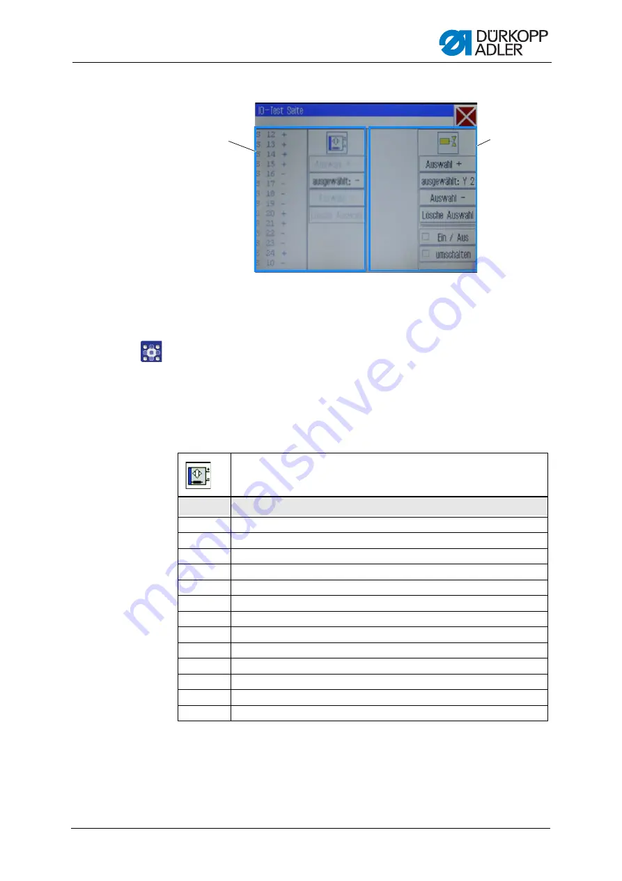
Fig. 53: Test inputs and outputs
The input elements are listed and selected at the left side (1) and the
output elements at the right side (2).
2.
For the 1
st
time: Press the button
selected:
and select an output.
3.
Next, use
Select
+
or
Select
-
to select the desired element
in the respective area.
The number of the element is displayed on the
selected:
button.
4.
Test the element using the
On/Off
or
Toggle
buttons, depending
on the type of the input or output element.
(1)
- Area for input elements
(2)
- Area for output elements
①
②
Input elements
No.
Meaning
S1
Lower right clamp
S2
Lower left clamp
S9
Needle thread monitor active
S10
Hook cover closed
S11
Machine head latch closed
S13
Pedal forwards
S14
Pedal backwards
S16
Pressure switch
S17
Quick-stop
S100
Sewing motor reference
S101
X-axis reference
S102
Y-axis reference
S103
Z-axis reference
Summary of Contents for 911-211-10
Page 1: ...911 211 10 Operating Instructions...
Page 6: ...Table of Contents 4 Operating Instructions 911 211 10 00 0 10 2020...
Page 10: ...About these instructions 8 Operating Instructions 911 211 10 00 0 10 2020...
Page 34: ...Operation 32 Operating Instructions 911 211 10 00 0 10 2020...
Page 88: ...Programming 86 Operating Instructions 911 211 10 00 0 10 2020...
Page 108: ...Setup 106 Operating Instructions 911 211 10 00 0 10 2020...
Page 110: ...Decommissioning 108 Operating Instructions 911 211 10 00 0 10 2020...
Page 112: ...Disposal 110 Operating Instructions 911 211 10 00 0 10 2020...
Page 133: ......


