A Related Documentation
Index
Figures
1–1
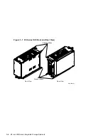
EF-Series ISE (Front and Rear View) . . . . . . . . . . . . . . . . . .
1–2
1–2
3.5-inch RZ-Series ISE (Rear View) . . . . . . . . . . . . . . . . . . . .
1–3
1–3
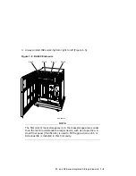
Front Panel Assembly . . . . . . . . . . . . . . . . . . . . . . . . . . . . . .
1–4
1–4
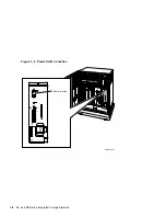
Power Switch Location . . . . . . . . . . . . . . . . . . . . . . . . . . . . . .
1–8
1–5
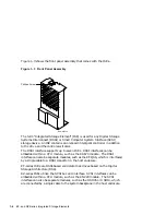
BA440 Enclosure . . . . . . . . . . . . . . . . . . . . . . . . . . . . . . . . . .
1–9
1–6
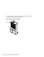
Blank Front Panel Assembly . . . . . . . . . . . . . . . . . . . . . . . . .
1–10
1–7
Removing the Plastic Skid Plate from the EF-Series ISE . . .
1–11
1–8
Installing the ISE in the Storage Cavity . . . . . . . . . . . . . . . .
1–12
1–9
Keylock Positions . . . . . . . . . . . . . . . . . . . . . . . . . . . . . . . . . .
1–15
1–10
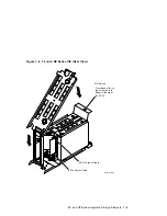
Removing the ISE to Be Upgraded or Replaced . . . . . . . . . . .
1–17
1–11
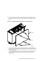
Removing the Top Outside Bracket from the ISE . . . . . . . . . .
1–19
1–12
Installing the Phillips Screws That Secure the Storage
Device to the Inside Brackets . . . . . . . . . . . . . . . . . . . . . . . . .
1–21
1–13
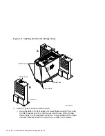
Installing the ISE Upgrade in the Storage Cavity . . . . . . . . .
1–23
2–1
Opening the Enclosure Doors . . . . . . . . . . . . . . . . . . . . . . . . .
2–4
2–2
Installing the TLZ07 Drive . . . . . . . . . . . . . . . . . . . . . . . . . .
2–6
3–1
Opening the Enclosure Doors . . . . . . . . . . . . . . . . . . . . . . . . .
3–3
3–2
Inserting the RRD CD–ROM drive . . . . . . . . . . . . . . . . . . . .
3–5
3–3
KZQSA IN Connector . . . . . . . . . . . . . . . . . . . . . . . . . . . . . . .
3–6
3–4
Removing the Connector Cover . . . . . . . . . . . . . . . . . . . . . . .
3–7
3–5
KZQSA Cable . . . . . . . . . . . . . . . . . . . . . . . . . . . . . . . . . . . . .
3–7
3–6
Connecting to KZQSA IN . . . . . . . . . . . . . . . . . . . . . . . . . . .
3–8
3–7
KZQSA Label . . . . . . . . . . . . . . . . . . . . . . . . . . . . . . . . . . . . .
3–9
3–8
KZQSA Module Connector . . . . . . . . . . . . . . . . . . . . . . . . . . .
3–9
3–9
Connecting to KZQSA IN . . . . . . . . . . . . . . . . . . . . . . . . . . .
3–10
4–1
Opening the Enclosure Doors . . . . . . . . . . . . . . . . . . . . . . . . .
4–3
4–2
Installing the RRD/TLZ07 Dual ISE . . . . . . . . . . . . . . . . . . .
4–5
5–1
TZ86 Tape Drive Front Panel . . . . . . . . . . . . . . . . . . . . . . . . .
5–1
5–2
Power Switch Location . . . . . . . . . . . . . . . . . . . . . . . . . . . . . .
5–4
5–3
Installing the TZ-Series Drive . . . . . . . . . . . . . . . . . . . . . . . .
5–6
5–4
TZ-Series Drive Installed in Mass Storage Slot 0 . . . . . . . . . .
5–7
v

