Note
If the DIP switches on the TLZ07 drive are used to set the bus node ID,
ensure that all of the bus node ID jumpers are removed. If the jumpers
are used to set the bus node ID on the TLZ07 drive, ensure that all of
the bus node ID DIP switches are set to 0.
In VAX 4000 systems, the SCSI termination and TERM PWR are provided by
the controller module on one end of the bus and termination for the other end
of the bus is provided by an external terminator.
Note
Refer to Section 1.4.4 for bus node ID configuration guidelines.
4.3 Installation Procedure
Use the following procedure to install the dual ISE drives into a BA400-series
enclosure. Have the system manager shut down the operating system before
installing the ISE.
CAUTION
Static electricity can damage integrated circuits. Use the antistatic
wrist strap and antistatic pad found in the static-protective field service
kit (29-26246-00) when you work with the internal parts of a computer
system.
1.
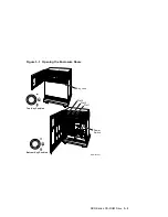
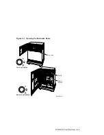
Open the top and bottom enclosure doors.
2.
Power off the system and unplug the power cord from the wall outlet.
3.
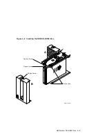
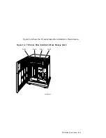
Loosen the captive Phillips screw (at the top) and remove the drive front
panel and filler panel located in mass storage slot 0.
Note
The RRD/TLZ07 Dual ISE can be installed in slot 0 only.
4–2 RRD/TLZ07 Dual ISE Drives


