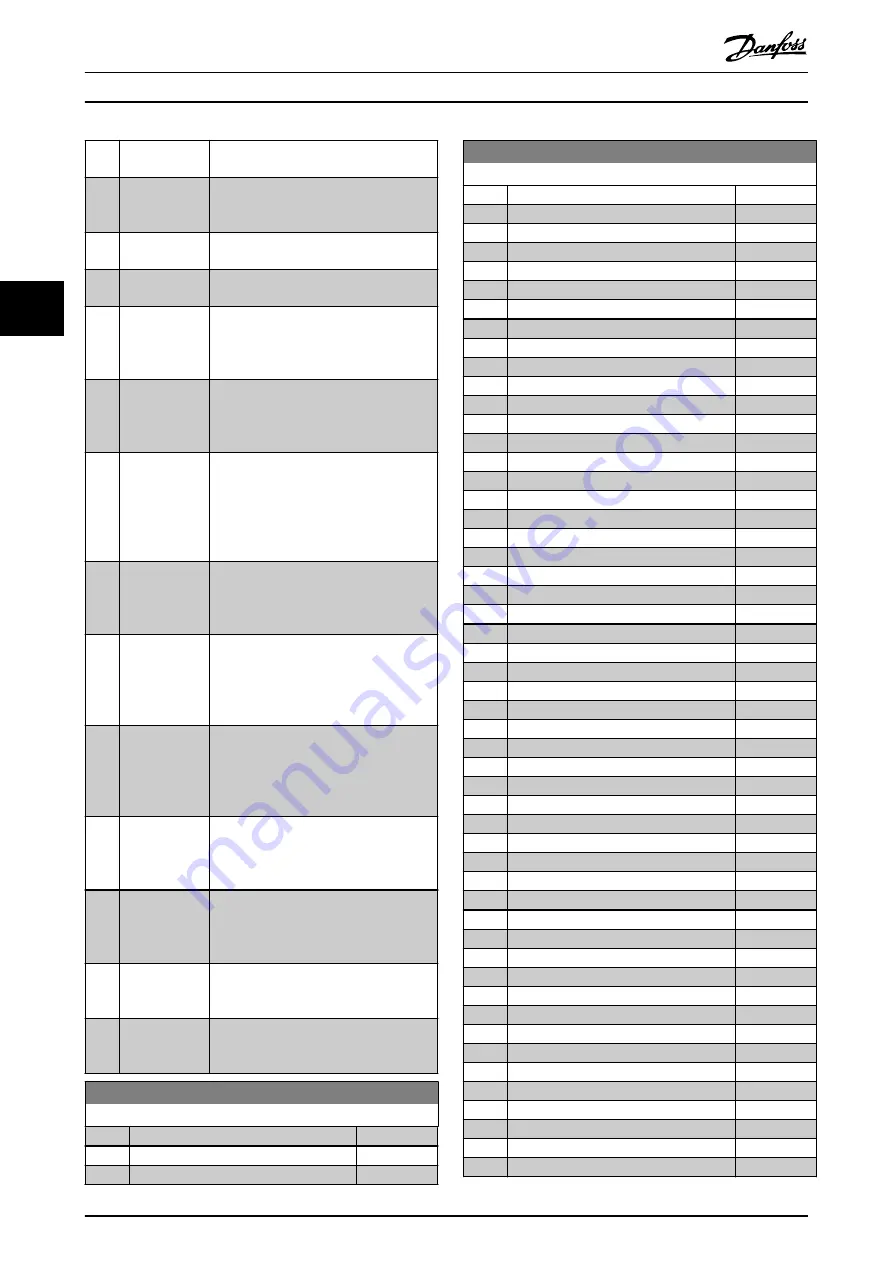
[166] Remote ref
active
[167] Start command
active
The output is high when there is an
active start command, and no stop
command is active.
[168] Drive in hand
mode
The output is high when the frequency
converter is in
Hand On
mode.
[169] Drive in auto
mode
The output is high when the frequency
converter is in
Auto On
mode.
[170] Homing
Completed
The homing operation is completed. This
option is only effective
when
parameter 37-00 Application Mode
is
set to
[2] Position Control
.
[171] Target Position
Reached
The target position is reached. This option
is only effective when
parameter 37-00 Application Mode
is set to
[2] Position Control
.
[172] Position
Control Fault
A fault occurred in the positioning
process. Refer to
for details about the fault.
This option is only effective when
parameter 37-00 Application Mode
is set to
[2] Position Control
.
[173] Position Mech
Brake
Selects mechanical control for positioning.
This option is only effective when
parameter 37-00 Application Mode
is set to
[2] Position Control
.
[174] TLD indicator
Indicates whether the tension is out of
limit (
on
) during center winding. This
option is only effective when
parameter 37-00 Application Mode
is set to
[1] Center winder
.
[175] Running on
tension
Indicates whether tension PID control is
active (
on
) or inactive (
off
). This option is
only effective when
parameter 37-00 Application Mode
is set to
[1] Center winder
.
[176] Ready to run
The center winder control is ready to run.
This option is only effective when
parameter 37-00 Application Mode
is set to
[1] Center winder
.
[177] End of roll
The diameter limit is reached. This option
is only effective when
parameter 37-00 Application Mode
is set to
[1] Center winder
.
[193] Sleep mode
The frequency converter/system has
entered sleep mode. See parameter group
22-4* Sleep Mode
.
[194] Broken belt
A broken belt condition has been
detected. See parameter group
22-4*
Sleep Mode
.
5-30 Terminal 27 Digital Output
Option:
Function:
[0]
*
No operation
[1]
Control Ready
[2]
Drive ready
5-30 Terminal 27 Digital Output
Option:
Function:
[3]
Drive rdy/rem ctrl
[4]
Stand-by / no warning
[5]
Running
[6]
Running / no warning
[7]
Run in range/no warn
[8]
Run on ref/no warn
[9]
Alarm
[10]
Alarm or warning
[11]
At torque limit
[12]
Out of current range
[13]
Below current, low
[14]
Above current, high
[15]
Out of frequency range
[16]
Below frequency, low
[17]
Above frequency, high
[18]
Out of feedb. range
[19]
Below feedback, low
[20]
Above feedback, high
[21]
Thermal warning
[22]
Ready, no thermal warning
[23]
Remote,ready,no TW
[24]
Ready, no over-/ under voltage
[25]
Reverse
[26]
Bus OK
[27]
Torque limit & stop
[28]
Brake, no brake warning
[29]
Brake ready, no fault
[30]
Brake fault (IGBT)
[31]
Relay 123
[32]
Mech brake ctrl
[36]
Control word bit 11
[37]
Control word bit 12
[40]
Out of ref range
[41]
Below reference, low
[42]
Above ref, high
[43]
Extended PID Limit
[45]
Bus ctrl.
[46]
Bus control, timeout: On
[47]
Bus control, timeout: Off
[55]
Pulse output
[56]
Heat sink cleaning warning, high
[60]
Comparator 0
[61]
Comparator 1
[62]
Comparator 2
[63]
Comparator 3
[64]
Comparator 4
[65]
Comparator 5
[70]
Logic rule 0
[71]
Logic rule 1
[72]
Logic rule 2
[73]
Logic rule 3
[74]
Logic rule 4
Parameter Descriptions
VLT
®
AutomationDrive FC 360
54
Danfoss A/S © 7/2015 All rights reserved.
MG06C602
4
4


