EM11 User’s Manual
Appendix II
151
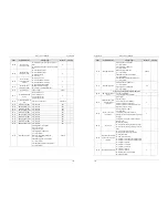
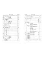
Code
Parameter Name
Setting range
Default
Property
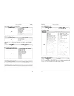
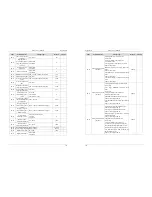
b4-06 DO3
function(extend)
26: Zero current state
27: Output current exceeded limitation
28: Lower voltage state output
29: Frequency inverter overload pre-warning
30: Motor overheat pre-warning
31: Motor overload pre-warning
32: off load
33: AI1 larger than AI2
34: AI1 input exceeded limitation
35: Alarm output (all faults)
36: Present running time reached
37: Accumulative power-on time reached
38: Accumulative running time reached
0
☆
b4-07 DO4
function(extend)
0
☆
b4-08 DO5
function(extend)
0
☆
b4-09 DO6
function(extend)
0
☆
b4-10
FMR ON delay time 0.0s~3000.0s
0.0s
☆
b4-11
FMR OFF delay time 0.0s~3000.0s
0.0s
☆
b4-12
Relay 1 ON delay time 0.0s~3000.0s
0.0s
☆
b4-13 Relay 1 OFF delay time 0.0s~3000.0s
0.0s
☆
b4-16
DO1 ON delay time 0.0s~3000.0s
0.0s
☆
b4-17
DO1 OFF delay time 0.0s~3000.0s
0.0s
☆
b4-18
DO2 ON delay time 0.0s~3000.0s
0.0s
☆
b4-19
DO2 OFF delay time 0.0s~3000.0s
0.0s
☆
b4-20
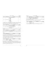
DO logic selection 1
Unit's digit: FMR valid mode.
0: Positive logic
1: Negative logic
Ten's digit: Relay 1 valid mode.
0, 1 (same as FMR)
Hundred's digit: Relay 2 valid mode.
0, 1 (same as FMR)
Thousand's digit: DO1 valid mode.
0, 1 (same as FMR)
Ten thousand's digit: DO2 valid mode.
0, 1 (same as FMR)
00000
☆
b4-21
DO logic selection 2
Unit's digit: DO3 valid mode.
0: Positive logic
1: Negative logic
Ten's digit: D04 valid mode.
0, 1 (same as FMR)
Hundred's digit: DO5 valid mode.
0, 1 (same as FMR)
Thousand's digit: DO6 valid mode.
0, 1 (same as FMR)
Ten thousand's digit: reserved
00000
☆
b4-22
Frequency detection
value (FDT1)
0.00 Hz~ maximum frequency
50.00 Hz
☆
b4-23
Frequency detection
hysteresis (FDT
hysteresis 1)
0.0%~100.0% (FDT1 level)
5.0%
☆
Appendix II
EM11 User’s Manual
152
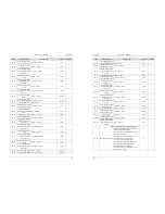
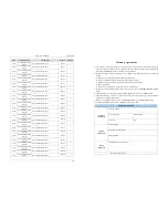
Code
Parameter Name
Setting range
Default
Property
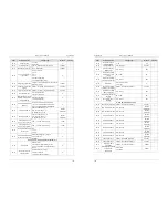
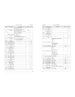
b4-24
Frequency detection
value (FDT2)
0.00Hz ~ maximum frequency
50.00 Hz
☆
b4-25
Frequency detection
hysteresis (FDT
hysteresis 2)
0.0%~100.0% (FDT2 level)
5.0%
☆
b4-26
Detection amplitude of
frequency reached
0.00~100% (maximum frequency)
3.0%
☆
b4-27
Any frequency reaching
detection value 1
0.00 Hz ~ maximum frequency
50.00 Hz
☆
b4-28
Any frequency reaching
detection amplitude 1
0.0%~100.0% (maximum frequency)
3.0%
☆
b4-29
Any frequency reaching
detection value 2
0.00 Hz ~ maximum frequency
50.00 Hz
☆
b4-30
Any frequency reaching
detection amplitude 2
0.0%~100.0% (maximum frequency)
3.0%
☆
b4-31
Zero current detection
level
0.0%~100.0% (rated motor current)
5.0%
☆
b4-32
Zero current detection
delay time
0.00s~600.00s 0.10s
☆
b4-33
Over current output
threshold
0.0%~300.0% (rated motor current)
200.0%
☆
b4-34
Over current output
detection delay time
0.00s~600.00s 0.10s
☆
b4-35
Any current reaching 1 0.0%~100.0% (rated motor current)
100.0%
☆
b4-36
amplitude of any current
reaching 1
0.0%~100.0% (rated motor current)
3.0%
☆
b4-37
Any current reaching 2 0.0%~100.0% (rated motor current)
100.0%
☆
b4-38
Amplitude of any
current reaching 2
0.0%~100.0% (rated motor current)
3.0%
☆
b4-39
Module temperature
threshold
25~100°C 75°C
☆
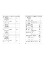
Group b5: Pulse/Analog input terminals
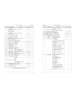
b5-00
Pulse minimum
input(HDI6)
0.00 kHz ~b5-02
0.00 kHz
☆
b5-01
Corresponding setting
of pulse minimum input
-100.00% ~100.0%
0.00%
☆
b5-02
Pulse maximum input b5-00 ~ 50.00 kHz
50.00 kHz
☆
b5-03
Corresponding setting
of pulse maximum input
-100.00% ~100.0%
100.0%
☆
b5-04
Pulse filter time
0.00s~10.00s
10.00s
☆
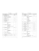
b5-05
AI1 input voltage lower
limit of protection
0.00 V~ b5-06
3.10 V
☆
b5-06
AI1 input voltage upper
limit of protection
b5-05~10.00 V
6.80 V
☆
b5-07
AI1input minimum
value
0.00 V ~ b5-15
0.00 V
☆

