EM11 User’s Manual
5. Description of Function Codes
113
Code
Parameter Name
Setting Range
Default
d2-12
Voltage source for
V/F separation
0: Digital setting (d2-13)
1: AI1
2: AI2
3: AI3
4: Pulse setting (DI6)
5: Multi-function
6: Simple PLC
7: PID
8: Communication setting
(Note: 100.0% corresponds to the rated motor voltage)
0
d2-13
Voltage digital setting
for V/F separation
0 V ~ rated motor voltage
0 V
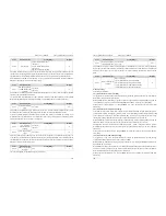
V/F separation is generally applicable to these sites, such as induction heating, inverse power supply and
motor torque control.
If V/F separated control is enabled, the output voltage can be set in d2-13 or by analog, Multi-function,
simple PLC, PID or communication. If you set the output voltage by means of non-digital setting, 100% of
the setting corresponds to the rated motor voltage. If a negative percentage is set, its absolute value is used
as the effective value.
0: Digital setting (d2-13)
The output voltage is set directly in d2-13.
1: AI1;
2: AI2;
3: AI3
The output voltage is set by analog input terminals.
4: Pulse setting (DI6)
The output voltage is set by pulses of the terminal DI6.
Pulse setting specification: voltage range 9V~30 V, frequency range 0kHz~100 kHz
5: Multi-function
6: Simple PLC
If the voltage source is simple PLC mode, parameters in group FC must be set to determine the setting
output voltage.
7: PID
The output voltage is generated based on PID closed loop. For details, see the description of PID in group
C0.
8: Communication setting
The output voltage is set by the host computer by means of communication.
The voltage source for V/F separation is selected in the similar way to the frequency source selection. For
details, see b0-03 (main frequency source X specification). 100.0% of the setting in each mode corresponds
to the rated motor voltage. If the corresponding value is negative, its absolute value is used.
Code
Parameter Name
Setting Range
Default
d2-14
Voltage rise time of
V/F separation
0.0s~1000.0s
Note: It indicates the time for the voltage rising from 0 V
~ rated motor voltage.
0.0s
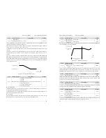
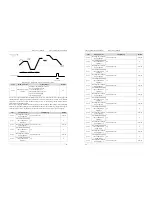
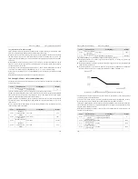
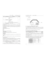
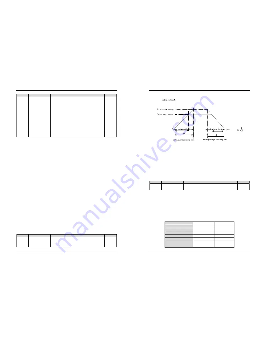
d2-14 indicates the time required for the output voltage to rise from 0 V to the rated motor voltage shown
5. Description of Function Codes
EM11 User’s Manual
114
as t1 in the following figure.
Diagram 5-33 Voltage of V/F separation
5.21 Group d3 to d5: Relevant parameters of motor 2
EM11 series support the switchover of two groups of motor parameters, and the two motors can separately
set the motor nameplate parameters, motor auto-tuning parameters, V/F control or vector control mode, the
related parameters of encoder and the related performance parameters of V/F control or vector control
mode.
For the setting of motor 2, please refer to the relevant description of motor1 parameters.
5.22 Group d6: Control Optimization Parameters
Code
Parameter Name
Setting Range
Default
d6-00
Carrier frequency 0.5kHz~15.0 kHz
Model
dependent
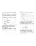
It is used to adjust the carrier frequency of the frequency inverter, helping to reduce the motor noise,
avoiding the resonance of the mechanical system, and reducing the leakage current to earth and interference
generated by the frequency inverter.
If the carrier frequency is low, output current has high harmonic wave, and then the motor will increase
power loss and temperature rising.
If the carrier frequency is higher, the power loss and temperature rising of the motor will decline. However,
the frequency inverter will have an increasing in power loss, temperature rising and interference.
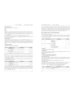
Adjusting the carrier frequency will exert influences on the aspects listed in the following table.
Table 6-1 Influences of carrier frequency adjustment
Carrier frequency
Low
→
High
Motor noise
Large
→
Small
Output current
Bad
→
Good
Motor temperature
High
→
Low
Frequency inverter
Low
→
High
Leakage current
Small
→
Large
External radiation
interference
Small
→
Large

