


EM11 User’s Manual
5. Description of Function Codes
83
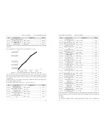
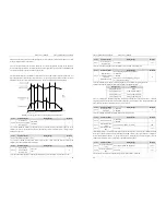
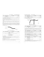
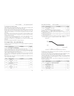
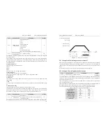
function. This function will be carried out by frequency inverter, when the current exceeds bb-07. This value
is the percentage of motor rated current.
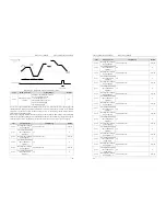
bb-06 (over current stall gain) is used to adjust the over current suppression capacity of the frequency
inverter. The larger the value is, the greater the over current suppression capacity will be. In condition of no
over current occurrence, should set bb-06 to a small value.
For small-inertia load, the value should be small. Otherwise, the system dynamic response will be slow. For
large-inertia load, the value should be large. Otherwise, the suppression result will be poor and over current
fault may occur. If the over current stall gain is set to 0, the over current stall function is disabled.
Diagram 5-23 Diagram of the over current stall protection function
Code
Parameter Name
Setting Range
Default
bb-08
Protection of
short-circuit to ground
after power-on
0: Disabled
1: Enabled
1
It is used to determine whether to check the motor is short-circuited to ground after power-on of the
frequency inverter. If this function is enabled, the frequency inverter's UVW will have voltage output a
while after power-on.
Code
Parameter Name
Setting Range
Default
bb-09 Fault auto reset times
0~99
0
It is used to set the times of fault auto resets if this function is used. After the value is exceeded, the
frequency inverter will remain in the fault state.
Code
Parameter Name
Setting Range
Default
bb-10
Relay action
selection during
fault auto reset
0: Not act
1: Act
0
It is used to decide whether DO acts during the fault auto reset if the fault auto reset function is used.
5. Description of Function Codes
EM11 User’s Manual
84
Code
Parameter Name
Setting Range
Default
bb-11
Time interval of
fault auto reset
0.1s~100.0s
1.0s
It is used to set the waiting time from the frequency inverter alarm to fault auto reset.
Code
Parameter Name
Setting Range
Default
bb-12
Input phase loss
protection/contactor
energizing
protection selection
Unit's digit: Input phase loss protection
0: Disabled
1: Enabled
Ten's digit: Contactor energizing protection
0,1( same as Unit’s digit)
0
It is used to determine whether to perform input phase loss or contactor energizing protection.
The EM11 models that provide this function are listed in the following table.
Voltage Class
Models
Single-phase 220 V
None
Three-phase 220 V
From 11 kW G model
Three-phase 380 V
From 18.5 kW G model
Three-phase 690 V
From 18.5 kW G model
For every voltage class, the EM11 frequency inverters provide function of input phase loss or contactor
energizing protection for above model. The EM11 Frequency inverters do not have this function below the
power listed in the table no matter whether bb-12 is set to 0 or 1.
Code
Parameter Name
Setting Range
Default
bb-13
Output phase loss
protection
0: Disabled
1: Enabled
0
It is used to determine whether to perform output phase loss protection.
Code
Parameter Name
Setting Range
Default
bb-14
Off load protection
0: Disabled
1: Enabled
0
bb-15
Off load detection
level
0.0%~100.0% (rated motor current)
1.0%
bb-16
Off load detection
time
0.0s~60.0s
1.0s
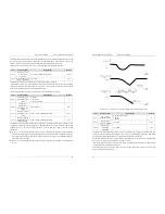
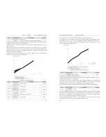
If off load protection is enabled, when the output current of the frequency inverter is lower than the detection
level (bb-15) and the duration time exceeds the detection time (bb-16), the output frequency of frequency
inverter automatically declines to 7% of the rated frequency. During the protection, the frequency inverter
automatically accelerates to the set frequency if the load restore to normal.
Code
Parameter Name
Setting Range
Default
bb-17
Over-speed detection
value
0.0%~50.0% (maximum frequency)
20.0%
bb-18
Over-speed detection
time
0.0s~60.0s
1.0s
This function is valid only when the frequency inverter runs in the VC+PG mode.