EM11 User’s Manual
5. Description of Function Codes
43
corresponding frequency values change display.
This parameter is not restored when factory fault setting is done.
Code
Parameter Name
Setting Range
Default
b0-12
Preset frequency
0.00 ~ maximum frequency (b0-13)
50.00 Hz
If the frequency source is digital setting or terminal UP/DOWN, the value of this parameter is the initial
frequency of the frequency inverter (digital setting).
Code
Parameter Name
Setting Range
Default
b0-13
Maximum frequency
50.00~3000.00 Hz
50.00 Hz
When the frequency source is AI, pulse setting (DI6), or Multi-segment speed, the 100% of input
corresponds to the value of this parameter.
The output frequency of the EM11 can reach up to 3000 Hz. To take both frequency reference resolution
and frequency input range into consideration, you can set the number of decimal places for frequency
reference in b0-11.
If b0-11 is set to 1, the frequency reference resolution is 0.1 Hz. In this case, the setting range of b0-13 is
50.0 to 3000.0 Hz.
If b0-11 is set to 2, the frequency reference resolution is 0.01 Hz. In this case, the setting range of b0-13
is 50.00 to 300.00 Hz.
Note:
After the value of b0-11 is modified, the frequency resolution of all frequency related function codes
change accordingly.
Code
Parameter Name
Setting Range
Default
b0-14
Source of frequency upper
limit
0: Set by (b0-15)
1: AI1
2: AI2
3: AI3
4: Pulse setting (DI6)
5: Communication setting
0
It is used to set the source of the frequency upper limit, including digital setting (b0-15), AI, pulse setting or
communication setting. If the frequency upper limit is set by means of AI1, AI2, AI3, DI5 or
communication, the setting is similar to that of the main frequency source X. For details, see the description
of b0-03.
For example, to avoid runaway in torque control mode in winding machine application, you can set the
frequency upper limit by means of analog input. When the frequency inverter reaches the upper limit, it will
run at this limited speed.
Code
Parameter Name
Setting Range
Default
b0-15
Frequency upper limit
Frequency lower limit (b0-17)~maximum
frequency (b0-13)
50.00 Hz
This parameter is used to set the frequency upper limit.
Code
Parameter Name
Setting Range
Default
b0-16
Frequency upper limit offset
0.00 Hz~ maximum frequency(b0-13)
0.00 Hz
If the source of the frequency upper limit is analog input or pulse setting, the final frequency upper limit is
obtained by adding the offset in this parameter to the frequency upper limit set in b0-14.
Code
Parameter Name
Setting Range
Default
b0-17
Frequency lower limit
0.00 Hz ~frequency upper limit(b0-15)
0.00 Hz
If the frequency command is lower than the value of this parameter, the frequency inverter can stop, or run
at the frequency lower limit, or run at zero speed. The result can be determined by b2-17(setting frequency
lower than frequency lower limit running mode).
5. Description of Function Codes
EM11 User’s Manual
44
Code
Parameter Name
Setting Range
Default
b0-18
Rotation direction
0: Forward direction
1: Reverse direction
0
You can change the rotation direction of the motor just by modifying this parameter without changing the
motor wiring. Modifying this parameter is equivalent to exchanging any two phase of the motor's U, V, W
wires.
Note:
The motor will restore original running direction after parameter initialization (A0-09). Do not use this
function in applications where changing the rotating direction of the motor is prohibited after system
commissioning is complete.
Code
Parameter Name
Setting Range
Default
b0-19
Base frequency for UP/
DOWN modification during
running
0: Running frequency
1: Setting frequency
0
This parameter is valid only when the frequency source is digital setting.
It is used to set the base frequency to be modified by using keys
and
or the terminal UP/DOWN
function. If the running frequency and setting frequency are different, there will be a large difference
between the frequency inverter's performance during the acceleration/ deceleration process.
Code
Parameter Name
Setting Range
Default
b0-20
Acceleration/Deceleration
mode
0: Linear acceleration/ deceleration
1: S-curve acceleration/deceleration A
2: S-curve acceleration/deceleration B
0
It is used to set the frequency changing mode during the frequency inverter start and stop process.
0: Linear acceleration/deceleration
The output frequency increases or decreases in linear mode. The EM11 provides four groups of
acceleration/deceleration time, which can be selected by using multi-function DI terminals (b3-00 to b3-11).
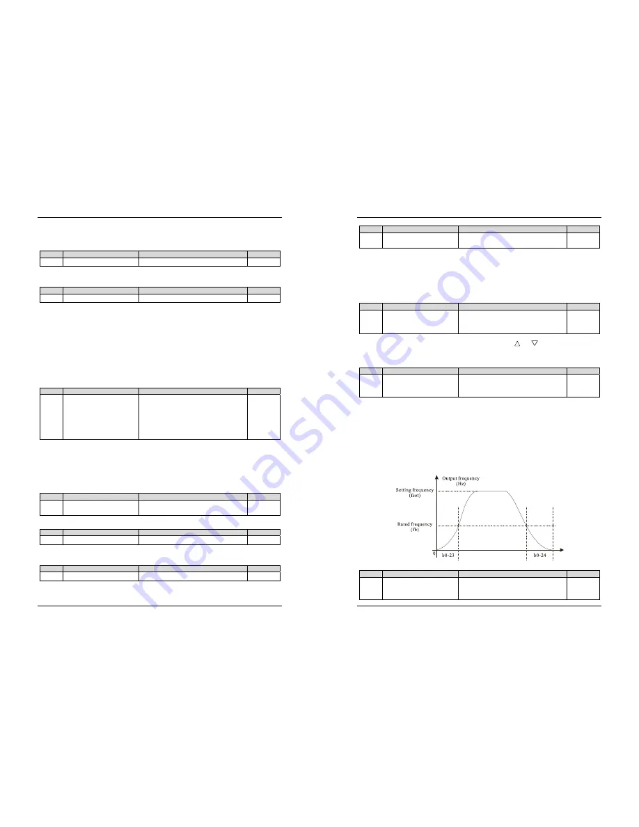
1: S-curve acceleration/deceleration A
The output frequency increases or decreases along the S curve. This mode is generally used in the
applications where start and stop processes are required relatively smooth, such as elevator and conveyor
belt. The b0-23 and b0-24 respectively define the time proportions of the start segment and the end segment.
2: S-curve acceleration/deceleration B
In this curve, the rated motor frequency fb is always the inflexion point of S curve. This mode is usually
used in applications where acceleration/deceleration is required at the speed higher than the rated frequency.
Diagram 5-2 S-curve acceleration/deceleration B diagram
Code
Parameter Name
Setting Range
Default
b0-21
Acceleration time 1
0.00s~650.00s (b0-25 = 2)
0.0s~6500.0s (b0-25 = 1)
0s~65000s (b0-25 = 0)
Model
dependent


