EM11 User’s Manual
5. Description of Function Codes
115
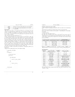
The factory setting of carrier frequency varies with the frequency inverter power. If you need to modify the
carrier frequency, note that if the set carrier frequency is higher than factory setting, it will lead to an
increase in temperature rise of the frequency inverter's heatsink. In this case, you need to de-rate the
frequency inverter. Otherwise, the frequency inverter may overheat and alarm.
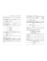
Code
Parameter Name
Setting Range
Default
d6-01
DPWM switchover
frequency upper limit
0.00Hz~15.00 Hz
12.00 Hz
This parameter is valid only for V/F control.
It is used to determine the wave modulation mode in V/F control of asynchronous motor. If the frequency is
lower than the value of this parameter, the waveform is 7-segment continuous modulation. If the frequency
is higher than the value of this parameter, the waveform is 5-segment intermittent modulation.
The 7-segment continuous modulation causes more wastage of IGBT switches of the frequency inverter but
smaller current ripple. The 5-segment intermittent modulation causes less wastage of IGBT switches of the
frequency inverter but larger current ripple. This parameter may lead to motor running instability at high
frequency. Do not modify this parameter generally.
For instability of V/F control, refer to parameter d2-10. For wastage of frequency inverter and temperature
rising, please refer to parameter d6-00.
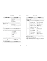
Code
Parameter Name
Setting Range
Default
d6-02
PWM modulation
mode
0: Asynchronous modulation
1: Synchronous modulation
0
This parameter is valid only for V/F control.
Synchronous modulation indicates that the carrier frequency varies linearly with the change of the output
frequency, ensuring that the ratio of carrier frequency to output frequency remains unchanged. Synchronous
modulation is generally used at high output frequency, which helps improve the output voltage quality.
At low output frequency (100 Hz or lower), synchronous modulation is not required. This is because ratio
of carrier frequency to output frequency is still high, and asynchronous modulation is more superior at such
low running frequency.
Synchronous modulation takes effect only when the running frequency is higher than 85 Hz. If the
frequency is lower than 85 Hz, asynchronous modulation is always valid.
Code
Parameter Name
Setting Range
Default
d6-03
Carrier frequency
adjustment with
temperature
0: No
1: Yes
1
It is used to set whether the carrier frequency is adjusted based on the temperature. The frequency inverter
automatically reduces the carrier frequency when detecting that the heatsink temperature is high. The
frequency inverter restores the carrier frequency to the set value when the heatsink temperature becomes
normal. This function is used to reduces the overheat alarms.
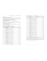
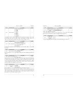
Code
Parameter Name
Setting Range
Default
d6-04
Random PWM depth
0: Random PWM invalid
1~10: Random PWM carrier frequency depth
0
5. Description of Function Codes
EM11 User’s Manual
116
The setting of random PWM depth can make the motor shrill noise to soft and reduce the electromagnetic
interference to other equipments. If this parameter is set to 0, random PWM is invalid.
Code
Parameter Name
Setting Range
Default
d6-05
Dead zone
compensation mode
selection
0: No compensation
1: Compensation mode 1
2: Compensation mode 2
1
Generally, you need not modify this parameter. Try to use a different compensation mode only when there
is special requirement on the output voltage waveform quality or oscillation occurs on the motor.
For high power frequency inverter, compensation mode 2 is recommended.
Code
Parameter Name
Setting Range
Default
d6-06
SVC mode selection
0: SVC mode 0
1: SVC mode 1
1
SVC mode 0: Used in the application that high speed stability required.
SVC mode 1: Used in the application that high torque control linearity required.
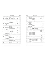
5.23 Group U0: Monitoring Parameters
Group U0 is used to monitor the frequency inverter's running state. You can view the parameter values by
using operation panel, convenient for on-site commissioning, or from the host computer by means of
communication (address: 0x7000 ~ 0x7044).
U0-00 ~ U0-31 are the monitoring parameters in the running and stop state defined by b9-02 and b9-03.
For more details, see Table 6-1.
Code
Parameter Name
Display Range
U0-00
Running frequency 0.00~300.00 Hz (b0-11 = 2)
0.00~3000.0 Hz (b0-11 = 1)
U0-01
Setting frequency
These two parameters display the absolute value of theoretical running frequency and set frequency. For the
actual output frequency of the frequency inverter, see U0-19.
Code
Parameter Name
Display Range
U0-02
DC Bus voltage
0.0~3000.0 V
It displays the frequency inverter's DC bus voltage.
Code
Parameter Name
Display Range
U0-03
Output voltage
0V~1140 V
It displays the frequency inverter's output voltage in the running state.
Code
Parameter Name
Display Range
U0-04
Output current
0.00A~655.35 A (Frequency inverter power
≤
55 kW)
0.0A~6553.5 A (Frequency inverter power > 55 kW)
It displays the frequency inverter's output current in the running state.
Code
Parameter Name
Display Range
U0-05
Output power
0~32767

