EM11 User’s Manual
5. Description of Function Codes
59
Code
Name
Value
Function Description
b3-13
Terminal command mode
2
Three-line 1
b3-00
DI1 function selection
1
Forward RUN (FWD)
b3-01
DI2 function selection
2
Reverse RUN (REV)
b3-02
DI3 function selection
3
Three-line control
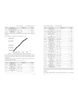
Diagram 5-12 Setting of three-line mode 1
As shown in the preceding figure, if SB1 is ON, the frequency inverter instructs forward rotation when Sb2
is pressed to be ON, and instructs reverse rotation when SB3 is pressed to be ON. The frequency inverter
stops immediately after SB1 becomes OFF. During normal startup and running, SB1 must remain ON. The
frequency inverter's running state is determined by the final actions on SB1, SB2 and SB3.
3: Three-line mode 2
In this mode, DI3 is RUN enabled terminal. The RUN command is given by DI1 and the direction is decided
by DI2. The parameters are set as below:
Code
Name
Value
Function Description
b3-13
Terminal command mode
3
Three-line 2
b3-00 DI1
function
selection
1 RUN
enabled
b3-01
DI2 function selection
2
Forward or reverse
b3-02
DI3 function selection
3
Three-line control
Diagram 5-13 Setting of three-line mode 2
As shown in the preceding figure, if SB1 is ON, the frequency inverter starts running when SB2 is pressed to
be ON; the frequency inverter instructs forward rotation when K is OFF and instructs reverse rotation when
K is ON. The Frequency inverter stops immediately after SB1 becomes OFF. During normal startup and
running, SB1 must remain ON
,
SB2 is effective immediately after ON action.
Code
Parameter Name
Setting Range
Default
b3-14
Terminal UP/DOWN rate
0.001Hz/s~65.535 Hz/s
0.100 Hz/s
It is used to adjust the ratio of changing of frequency for per second when the frequency is adjusted by
means of terminal UP/ DOWN.
5. Description of Function Codes
EM11 User’s Manual
60
1.
If b0-11 (Frequency reference resolution) is 2, the setting range is 0.001Hz/s~65.535 Hz/s.
2.
If b0-11 (Frequency reference resolution) is 1, the setting range is 0.01Hz/s~655.35 Hz/s.
Code
Parameter Name
Setting Range
Default
b3-15
DI1 ON delay time
0.0s~3000.0s
0.0s
b3-16
DI1 OFF delay time
0.0s~3000.0s
0.0s
b3-17
DI2 ON delay time
0.0s~3000.0s
0.0s
b3-18
DI2 OFF delay time
0.0s~3000.0s
0.0s
b3-19
DI3 ON delay time
0.0s~3000.0s
0.0s
b3-20
DI3 OFF delay time
0.0s~3000.0s
0.0s
b3-21
DI4 ON delay time
0.0s~3000.0s
0.0s
b3-22
DI4 OFF delay time
0.0s~3000.0s
0.0s
b3-23
DI5 ON delay time
0.0s~3000.0s
0.0s
b3-24
DI5 OFF delay time
0.0s~3000.0s
0.0s
These parameters are used to set the delay time of the frequency inverter when the status of DI terminals
changes.
The DI1 to DI5 support the delay time function.
Code
Parameter Name
Setting Range
Default
b3-25
DI valid selection 1
Unit's digit: DI1 valid mode.
0: Low level valid
1: High level valid
Ten's digit: DI2 valid mode.
0, 1 (same as DI1)
Hundred's digit: DI3 valid mode.
0, 1 (same as DI1)
Thousand's digit: DI4 valid mode.
0, 1 (same as DI1)
Ten thousand's digit: DI5 valid mode.
0, 1 (same as DI1)
00000
b3-26
DI valid selection 2
Unit's digit: DI6 valid mode.
0, 1 (same as DI1)
Ten's digit: DI7 valid mode.
0, 1 (same as DI1)
Hundred's digit: DI8 state.
0, 1 (same as DI1)
Thousand's digit: DI9 valid mode.
0, 1 (same as DI1)
Ten thousand's digit: DI10 valid mode.
0, 1 (same as DI1)
00000
These parameters are used to set the valid mode of DI terminals.
0: Low level valid
The DI terminal is invalid when being connected with COM, and valid when being disconnected from COM.
1: High level valid
The DI terminal is valid when being connected with COM, and invalid when being disconnected from COM.
5.5 Group b4: Output Terminals
The EM11 provides an analog output (AO) terminal, a digital output (DO) terminal, a relay terminal and a


