EM11 User’s Manual
2. Product Information
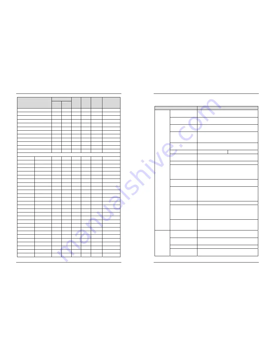
7
Model
Adaptable Motor Input
Current
(A)
Output
Current
(A)
Power
Capacity
(KVA)
Thermal Power
Consumption
(KW)
KW
HP
EM11- G2-004
3.7
5
14.6
13
8.9
0.132
EM11- G2-5d5
5.5
7.5
26
25
17
0.214
EM11- G2-7d5
7.5
10
35
32
21
0.288
EM11-
G2-011
11 15 46.5 45 30
0.489
EM11-
G2-015
15 20 62 60 40
0.608
EM11- G2-018
18.5
25
76
75
57
0.716
EM11-
G2-022
22 30 92 91 69
0.887
EM11- G2-030
30
40
113
112
85
1.11
EM11- G2-037
37
50
157
150
114
1.32
EM11- G2-045
45
60
180
176
134
1.66
EM11- G2-055
55
75
214
210
160
1.98
EM11-
G2-075
75 100 307 304 231
2.02
Three-phase 380V
,
50/60Hz
EM11- G3-d75
0.75
1
3.4
2.1
1.5
0.027
EM11- G3-1d5 EM11- P3-1d5
1.5
2
5
3.8
3
0.050
EM11- G3-2d2 EM11- P3-2d2
2.2
3
5.8
5.1
4
0.066
EM11- G3-004 EM11- P3-004
3.7
5
10.5
9
5.9
0.120
EM11- G3-5d5 EM11- P3-5d5
5.5
7.5
14.6
13
8.9
0.195
EM11- G3-7d5 EM11- P3-7d5
7.5
10
20.5
17
11
0.262
EM11- G3-011 EM11- P3-011
11
15
26
25
17
0.445
EM11- G3-015 EM11- P3-015
15
20
35
32
21
0.553
EM11-
G3-018
EM11-
P3-018
18.5 25 38.5 37 24
0.651
EM11- G3-022 EM11- P3-022
22
30
46.5
45
30
0.807
EM11- G3-030 EM11- P3-030
30
40
62
60
40
1.01
EM11- G3-037 EM11- P3-037
37
50
76
75
57
1.20
EM11- G3-045 EM11- P3-045
45
60
92
91
69
1.51
EM11- G3-055 EM11- P3-055
55
75
113
112
85
1.80
EM11- G3-075 EM11- P3-075
75
100
157
150
114
1.84
EM11- G3-090 EM11- P3-090
90
125
180
176
134
2.08
EM11- G3-110 EM11- P3-110
110
150
214
210
160
2.55
EM11-
G3-132
EM11-
P3-132
132 200 256 253 192
3.06
EM11-
G3-160
EM11-
P3-160
160 250 307 304 231
3.61
EM11-
G3-200
EM11-
P3-200
200 300 385 377 250
4.42
EM11-
G3-220
EM11-
P3-220
220 300 430 426 280
4.87
EM11-
G3-250
EM11-
P3-250
250 400 468 465 355
5.51
EM11-
G3-280
EM11-
P3-280
280 370 525 520 396
6.21
EM11-
G3-315
EM11-
P3-315
315 500 590 585 445
7.03
EM11-
G3-355
EM11-
P3-355
355 420 665 650 500
7.81
EM11-
G3-400
EM11-
P3-400
400 530 785 725 565
8.51
EM11-
P3-450
450 600 883 820 630
9.23
2. Product Information
EM11 User’s Manual
8
2.4 Technical Specifications
Table 2-2 Technical specifications of EM11
Item
Specifications
Standard
functions
Maximum frequency
Vector control: 0~300 Hz
V/F control: 0~3000 Hz
Carrier frequency
0.5–16 kHz (The carrier frequency is automatically adjusted
based on the load features.)
Input frequency resolution
Digital setting: 0.01 Hz
Analog setting: maximum frequency x 0.025%
Control mode
Sensor-less vector control (SVC)
Closed-loop vector control (VC)
(
+ PG card
)
Voltage/Frequency (V/F) control
Startup torque
G type: 0.5 Hz/150% (SVC); 0 Hz/180% (VC)
P type: 0.5 Hz/100%
Speed range
1:100 (SVC)
Speed range
Speed stability accuracy
± 0.5% (SVC)
± 0.02% (VC)
Torque control accuracy ± 5% (VC)
Overload capacity
G type: 60s for 150% of the rated current, 3s for 180% of the
rated current
P type: 60s for 120% of the rated current, 3s for 150% of the
rated current
Torque boost
Auto boost
Manual boost 0.1%~30.0%
V/F curve
Straight-line V/F curve
Multi-point V/F curve
N-power V/F curve (1.2-power, 1.4-power, 1.6-power,
1.8-power, square)
V/F separation
Two types: complete separation; half separation
Acceleration/deceleration
curve
Straight-line ramp
S-curve ramp
Four groups of acceleration/deceleration time with the range
of 0.0s~65000s
DC braking
DC braking frequency: 0.00 Hz ~ maximum frequency
Braking time: 0.0s~36.0s
Braking trigger current value: 0.0%~100.0%
Standard
functions
JOG control
JOG frequency range: 0.00Hz~50.00 Hz
JOG acceleration/deceleration time: 0.00s~6500.0s
Built-in simple PLC,
multiple speeds
It realizes up to 16 speeds via the simple PLC function or
combination of DI terminal states.
Built-in PID
It realizes closed loop control system easily.
Auto voltage regulation
(AVR)
It can keep constant output voltage automatically when the
mains voltage fluctuation.


