background image

7B-36 

M A N U A L   T R A N S M IS S IO N

1

.

M a in   D riv e   G e a r

1


1

.

R e v e rs e   D riv e n   G e a r

2

.

D riv e   G e a r   B e a r in g

1 2

.

P o p p e t  S p r in g

R e ta in e r

1 3 .

P o p p e t  B a ll

3.

S n a p   R in g -O u te r

1 4 .

S h ift  R ail

4.

3 r d   a n d   4 th

1 5 .

1st  a n d   2 n d   S h ift

S y n c h r o n iz e r   R in g

F o rk

5.

3 r d   a n d   4 th

1 6 .

1 st  S p e e d   G e a r

S y n c h r o n iz e r   C o lla r

1 7 .

T h r u s t  W a s h e r

6

.

3 r d   a n d   4 th   S h ift

1 8 .

B e a r in g   S n a p   R in g

F o rk

1 9 .

S p e e d o m e te r   D riv e

7.

3 r d   a n d   4 th   S p e e d

G e a r

S y n c h r o n iz e r   R in g

2 0

.

O u tp u t  Y o k e

8

.

3 r d   S p e e d   G e a r

2 1

.

F la n g e   N u t

9.

2 n d   S p e e d   G e a r

2 2

R e a r   B e a r in g

10

.

1

 st  a n d  

2

nd

R e ta in e r   O il  S e a l

S y n c h r o n iz e r

2 3

R e a r  B e a r in g

A s s e m b ly

R e ta in e r

2 4

M a in s h a f t   R e a r

3 7 .

T h r u s t  W a s h e r

B e a r in g

3 8 .

S n a p   R in g

2 5 .

R e a r   B e a r in g   S n a p

3 9 .

F r o n t  C o u n te r s h a ft

R ing

B e a r in g

2 6

S n a p   R in g

4 0

C o u n t e r g e a r   F ro n t

2 7

C o u n te r s h a ft

C o v e r

2 8

C o u n t e r s h a f t   R e a r

4 1 .

P ilo t  B e a r in g   R o lle rs

B e a r in g

4 2 .

C lu tc h   G e a r   O il

2 9

B e a r in g   S n a p   R in g

S lin g e r

3 0

R e v e rs e   Id le r   G e a r

4 3 .

S n a p   R in g

3 1 .

R e v e rs e   Id le r   S h a ft

4 4 .

3 r d   S p e e d   G e a r

3 2 .

C a s e   M a g n e t

B u s h in g

3 3 .

S n a p   R in g

4 5 .

T h r u s t   W a s h e r

3 4 .

S n a p   R in g

4 6 .

2 n d   S p e e d   G e a r

3 5 .

S p a c e r

B u s h in g

3 6

C o u n t e r g e a r

4 7 .

1 st  S p e e d   G e a r

B u s h in g

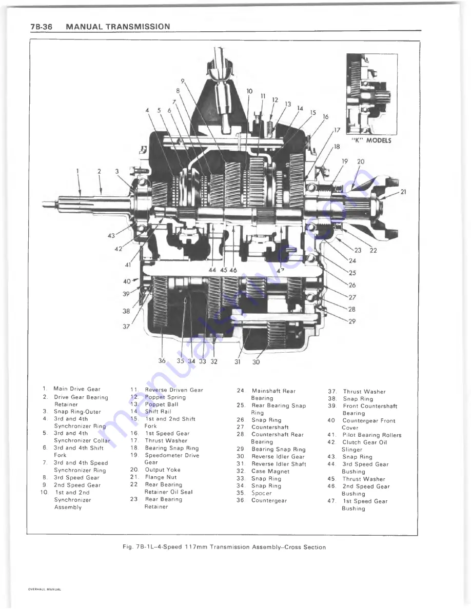
Fig.  7B-1 L--4-Speed  1  17mm  T ransm ission  A sse m b ly-C ro ss  S ection

O V E R H A U L   M A N U A L

Summary of Contents for 1977 Monte Carlo

Page 1: ...CHEVROLET ST 333 80...

Page 2: ...ject is a Table of Contents which gives the page number on which each major subject begins An index is placed at the beginning of each major subject within the section Summaries of Special Tools when...

Page 3: ...sonal injury to service personnel or the p ossib ility that im proper service m ethods w ill be fo llo w ed w hich m ay dam age the vehicle or render it unsafe It also is im portant to understand that...

Page 4: ......

Page 5: ...ial lines for this purpose while most customary nuts do not have strength markings Mismatched or incorrect fasteners can result in vehicle damage or malfunction or possibly personal injury There fore...

Page 6: ......

Page 7: ...ID 37 R 4 Compressor Pressure Relief Valve or Pressure Sw itch ID 37 R 4 Compressor Front Head and or O Ring 4 ID 37 R 4 Compressor Thrust and Belleville W ashers ID 39 R 4 Compressor Main Bearing ID...

Page 8: ...NDITIO NING section and Figure ID 2 and Figure ID 3 for information relative to parts nomenclature and location Removal and illustration of external compressor components and disassembly and assembly...

Page 9: ...IL PUMP COVER f O REAR DISCHARGE VALVE PLATE ASSEMBLY REAR SUCTION REED f A X IA L PLATE BUSHING I 0 V J G NEEDLE BEARING 4 O RING j REAR CYLINDER HALF BEARING BEARING RETAINER PULLEY RETAINER RING CL...

Page 10: ...RELIEFt V A L V E O IL PICK UP TUBE O IL SUMP REAR C Y LIN D E R H A LF THRU ST BEARING CLUTCH COIL A N D HOUSING CLUTCH PLATE A N D HUB ASSEMBLY S E A L SEAT R ETA IN ER RING SEAL SLEEVE Figure 1D 3...

Page 11: ...ng facing spacer 6 Using Thin Wall Socket J 9399 and Clutch Hub Holder J 25030 or J 9403 to install a new shaft locknut with shoulder or circular projection on the locknut facing towards retainer ring...

Page 12: ...before reinstallation Replace 1 If original Pulley and Bearing assembly is to be reinstalled wipe frictional surface of pulley clean If frictional surface of pulley shows any indication of damage due...

Page 13: ...17 The Installer will apply the force to the outer race of the bearing NOTICE DO NOT CLEAN NEW BEA RIN G ASSEMBLY W ITH A N Y TYPE OF SOLVENT Bearing is supplied with correct lubricant when assembled...

Page 14: ...ch or disassembly of the Internal Compressor Cylinder and Shaft Assembly are considered Major since the refrigeration system must be completely purged of refrigerant before proceeding and or because m...

Page 15: ...A 6 system must then also be removed oil drained measured etc according to same section S P E C IF IC A T IO N P A R T S S E A L I C A R S O N M A T E R IA L L A R G E C H A M F E R O N IN S ID E D 1...

Page 16: ...er by pressing downward and twisting counter clockwise 5 Attach the ceramic Seal Seat to the Seal Seat Remover and Installer J 23128 and dip the ceramic Seat in clean 525 viscosity refrigerant oil to...

Page 17: ...een the drive and driven plates dislocation of the shaft should be suspected If the carbon seal is not seating against the seal seat it will not be possible to completely Evacuate the System as outlin...

Page 18: ...quid measuring cup may be used for this purpose Drained oil should then be discarded 4 Remove four locknuts from threaded studs on compressor shell and remove rear head Tap uniformly around rear head...

Page 19: ...s side and push Front Head assembly through Compressor Sheel being careful not to damage sealing areas on inner side of front head Discard O ring It may be necessary to tap on outside of front head us...

Page 20: ...sly identified as No 1 with balls and shoe discs from axial plate a Inspect the Teflon piston rings for nicks cuts or metal particles imbedded in exposed ring surface and replace the piston rings as r...

Page 21: ...UST RACE then one thrust bearing and a SECOND ZERO THRUST RACE ONTO FRONT E N D of compressor shaft Lubricate races and bearing with petrolatum 4 Insert threaded end of axial shaft through needle bear...

Page 22: ...1 Piston over No 1 cylinder bore notched end of piston being on bottom and piston straddling axial plate and lower the shaft to allow No 1 Piston to drop into its bore Figure ID 43 11 Repeat Steps 6 t...

Page 23: ...t If shaft is hard to rotate install shaft nut onto shaft and turn shaft with wrench Figure 1D 45 Gaging A 6 Rear Piston Ball 17 Rotate shaft another 120 and again repeat Step 15 between these same pa...

Page 24: ...ed select a thrust race with a number corresponding to TWO 2 FULL SIZES LARGER than Dial Indicator or Feeler Gage measurement of the amount of end play shown If measurement is 007 select a No 9 or 090...

Page 25: ...the Piston and Ring Assembly in the Ring Sizer J 24608 6 several COMPLETE turns until the Assembly rotates relatively free in the Ring Sizer Figure ID 53 8 Remove the Piston and Ring Assembly wipe th...

Page 26: ...INSTALLER TEFLON RING Cylinder H alf over the shaft and start the pistons into the cylinder bore Figure ID 60 7 When all three Piston and Ring assemblies are in their respective cylinders align the e...

Page 27: ...tap it in until flush on both ends Figure 1D 56 Installing 1st A 6 Piston Assembly Into Front Figure 1D 57 Installing 2nd A 6 Piston A 6 COMPRESSOR INTERNAL CYLINDER AND SHAFT ASSEMBLY Re Install 1 P...

Page 28: ...Cylinder and Shaft Assembly with a grease pencil Carefully lower Front Head casting into position Figure ID 66 making certain that sealing area around center bore of head assembly does not contact sha...

Page 29: ...nd of shaft now facing downward Remove Support Block 12 Install new dowel pins in rear cylinder half if previously removed 13 Install new O ring in oil pick up tube cavity 14 Lubricate Oil Pick Up Tub...

Page 30: ...es with inner gear at the 9 o clock position The resulting cavity between gear teeth is then at 3 o clock position Figure ID 70 20 Generously oil Rear Discharge Valve Plate assembly with 525 viscosity...

Page 31: ...bed in A 6 Compressor Clutch Coil and Housing Assembly Replacement procedure 28 Install compressor Pulley and Bearing assembly as described in A 6 Compressor Pulley and Bearing Replacement procedure 2...

Page 32: ...shaft nut using Thin Wall Socket J 9399 Figure ID 77 3 Thread the Clutch Plate and Hub Assembly Remover J 9401 into the hub Hold the body of the Remover with a wrench and turn the center screw into t...

Page 33: ...T H R U S T W A S H E R S 1 BELLEVILLE W A S H E R O R IN G S U C TIO N D IS C H A R G E PORTS CLUTCH DRIVE A S S E M B LY C LU TC H H U B KEY S H A FT N U T VALVE PLATE RETAINER RING M A IN BEA RING...

Page 34: ...EW PULLEY RIM MTG SCREW LOCKWASHER ROTOR BEARING ROTOR BEARING RETAINER SEAL SEAT RETAINER SHAFT KEY SHAFT NUT SHAFT SEAL SEAL SEAT SEAL SEAT O RING C L U T C H DRIVE ASSEMBLY ROTOR AND HUB ASSEMBLY F...

Page 35: ...ced bend the lockwashers away from the pulley rim mounting screws see Figure ID 79 and remove the six mounting screws and special lock washers before proceeding with Step 3 Discard the lock washers 3...

Page 36: ...gure 1D 82 Installing R 4 Rotor and Bearing Puller Guide 2 Align the new bearing squarely with the hub bore and using Pulley and Bearing Installer J 9481 with Universal Handle J 8092 drive the bearing...

Page 37: ...BLY ON BENCH Reassemble the Rotor and Bearing assembly to the front head of the compressor using Rotor Bearing Installer J 26271 With Installer assembled to the Universal Handle J 8092 as shown in Fi...

Page 38: ...e ID 88 Figure 1D 89 R 4 Clutch Coil Assembly Replace 1 Assemble the Clutch Coil Pulley Rim and the Clutch Rotor and Bearing assembly as shown in Figure 1D 90 Use new special lock washers and apply se...

Page 39: ...or equivalent sealer on the threads and locked into place similar to the original locking method Procedure II INERTIA RING AND PULLEY RIM WELDED ASSEMBLY REPLACEMENT NEW PULLEY RIM AND INERTIA RING KI...

Page 40: ...screws are torqued in place lock all mounting screws in position by flattening the special washer against two opposite sides of the hex head screw using vise grip pliers Form a portion of the lock wa...

Page 41: ...ine oil loss R 4 COMPRESSOR SHAFT SEAL REPLACEMENT Remove On Car 1 Discharge the Refrigerant System according to the DISCH ARG ING A D D IN G OIL EVACUATING A N D C H A R G IN G PROCEDURES FOR C C O T...

Page 42: ...face of the new Seal assembly with clean 525 viscosity refrigerant oil Carefully mount the Seal assembly to Seal Installer J 9392 by engaging the tabs of the seal with the tangs of the Installer Figu...

Page 43: ...move 1 Discharge the Refrigerant System according to the DISCHARG ING A D D IN G OIL EVACUATING A N D C H A R G IN G PROCEDURES FOR C C O T A C SYSTEM in the A IR C O N D ITIO N IN G section 2 Perform...

Page 44: ...oil hole in the Front Head to be up when assembled to the compressor cylinder to correspond with the up position of the compressor Install the Front Head and tighten the front head mounting screws to...

Page 45: ...ashers with clean 525 viscosity refrigerant oil and assemble the Front Head and new O ring onto the compressor as described in R 4 Compressor Front Head Replacement procedure R 4 COMPRESSOR MAIN BEARI...

Page 46: ...alternately tighten each bolt approximately 1 4 turn to push the Shell free of the O rings on the cylinder if one screw appears to require more force to turn than the other immediately turn the other...

Page 47: ...ate replacement and or piston inspection Repeat this operation for additional valve plates and retainer rings If all four valve plates and retainers are to be removed remove two sets and then rotate c...

Page 48: ...ING A N D C H A R G IN G PROCEDURES FOR C C O T A C SYSTEMS in the AIR C O N D ITIO N IN G section 2 Remove the Clutch Plate and Hub assembly as described in R 4 Compressor Clutch Plate and Hub Remova...

Page 49: ...lution per second can result in a lower pump up pressure and disqualify a good pumping compressor 16 Observe the reading on HIGH pressure gage at the completion of the tenth revolution of the compress...

Page 50: ......

Page 51: ...ERING 3B 1 SECTION 3B STEERING CONTENTS OF THIS SECTION Manual Steering Gear 3B 1 Power Steering Pum p 3B 5 Integral Power Steering Gear 3B 8 Special T o o ls 3B 19 MANUAL STEERING GEARS OVERHAUL MANU...

Page 52: ...E COVER REMOVE 1 Center steering gear 2 Remove parts as shown INSTALL 1 Before installing turn preload adjuster screw counter clockwise until it bottom s then back screw o ff one half turn 2 Install p...

Page 53: ...STER DISASSEMBLE Pry lower bearing re tainer out with screw driver R e m o ve c u p u s in g J 5822 puller and slide hammer WORM BEARING ADJUSTER LOWER W ORM BEARING CUP LOWER WORM BEARING ASSEMBLE 1...

Page 54: ...G ADJUSTMENT TORQUE TO TURN WORM SHAFT Worm Bearing 0 6 1 0 N m 5 8 In Lbs Over Center Preload 0 5 1 2 N m 4 10 In Lbs in excess of Worm Bearing Preload Total Steering Gear Preload 1 8 N m 16 In Lbs M...

Page 55: ...ng gear or pump broken components or foreign material are encountered the remaining components of the entire hydraulic system should be disassembled inspected thoroughly cleaned and flushed before ser...

Page 56: ...r PUNCH REMOVE RETAINING RING I LUBRICATE END PLATE AND RETAINING RING INSTALL PARTS AS SHOWN REFER TO INSET FOR POSITIONING OF RETAINING RING IN HOUSING RETAINING RING LOCATE RING GAP AT POSITION SH...

Page 57: ...ur bolts SMALL GEAR 605 MODEL LARGE GEAR 800 808 MODEL Key No Port Name 1 HOUSING STEERING GEAR 2 RETAINER STRG COUPLING SHIELD 3 BEARING ASSY NEEDLE STUB SHAFT 4 SEAL STUB SHAFT 5 SEAL STUB SHAFT OUS...

Page 58: ...HIM STOCK Screw driver HOU SIN G ASSEMBLY OIL SEAL REMOVE AND INSTALL PITMAN SHAFT AND SIDE COVER REMOVE 1 If pitman shaft and side cover are to be separated remove preload adjuster nut IT IS A LEFT H...

Page 59: ...g from rack piston VALVE A N D W O R M ASSEM BLY DISASSEMBLE 1 Disassem ble parts as shown ASSEMBLE 2 Assem ble parts as shown VALVE B O D Y O RING VALVE B O D Y VALVE S P O O L T S TU B S H A F T 7 V...

Page 60: ...t top of seal with anhydrous calcium grease I Install dust seal just deep enough to clear retaining ring groove then install retaining ring HOUSING ASSEMBLY Inspect for burrs OIL SEAL WASHER DUST SEAL...

Page 61: ...Newton metres 6 to 10 in lbs metres 20 Ft lbs Prevent adjuster screw from turning while torqueing lock nut RECOMMENDED TORQUE SPECIFICATIONS NEWTON METRES Gear To Frame Bolts 95 High Pressure Line Fit...

Page 62: ...del 605 uses an acme thread on the worm which mates with an acme thread in the rack piston Round side cover held in SMALL GEAR 605 M O D EL Repair procedures for these two models are different Note th...

Page 63: ...T LOCK 32 NUT PITMAN SHAFT 33 NUT RACK PISTON 34 BALL 35 GUIDE BALL RETURN 2 36 CLAMP BALL RETURN GUIDE Key No Port Nome 37 SCREW ASSY LOCKWASHER 2 38 PLUG RACK PISTON 39 SEAL O RING RACK PISTON 40 RI...

Page 64: ...f removed install gasket seal by bending tabs around cover edges Install parts as shown SIDE COVER BOLTS Torque to 60 Newton Metres 45 Ft Lbs Separate pitman shaft and gasket seal from side cover if r...

Page 65: ...CE LARGE UPPER TH R U ST BEARING UPPER BEARING RACE SM ALL TH R UST BEARING SPACER BEARING RETAINER RETAINER VALVE BODY RING teflon S P O O LTO BODY O RING Shaft cap A Loosen shaft cap B Rem ove and i...

Page 66: ...Alternately install rem ainder of balls and retain with grease at each end of guide Installer J 22407 C LA M P W hen tool bottom s on housing bearing is fully in sta lled SCREW Tighten to 5 Newton Met...

Page 67: ...ighten adjuster plug until thrust bearing is firmly bottomed 27 Newton Metres 20 Ft Lbs C Turn adjuster in until torque to turn stub shaft is 0 6 to 1 2 Newton Metres 6 to 10 in Lbs more than reading...

Page 68: ...djustment it is necessary that the steering gear assembly be removed from the car and both thrust bearing and over center preload be checked and corrected as necessary An in car check of the steering...

Page 69: ...Teflon Ring Compressor J 6221 Bearing Installer J 21552 Ball Retainer J 6222 End Cover Seal Protector Used for Installing J 24319 01 Puller Adjuster Plug J 22407 Pitman Bearing Installer J 6278 Pitma...

Page 70: ......

Page 71: ...may be reinstalled at original lash to avoid changing gear tooth contact 1 Remove screw that retains differential pinion shaft and remove pinion shaft 2 Remove rear axle shafts as outlined in the Ser...

Page 72: ...earing on hub with thick side of inner race toward case and drive into place using J 22175 for 8 7 8 or J 22761 for 8 1 2 ring gear and Driver Handle J 8092 as shown in figure 4B 4 Before bearing inst...

Page 73: ...rs until the differential pinion bores and the case shaft holes are aligned 4 Install pinion shaft and lock screw It is not necessary to torque lock screw until axle shafts are installed 5 Differentia...

Page 74: ...0 Install left shim first then wedge right shim between bearing cup and spacer Position shim so that chamfered side is outward or next to spacer If shim does not have sufficient chamfer or lead around...

Page 75: ...damage pinion bearings while removing pinion from carrier Insoect bearings nrd cups for damage and replace if needed 9 Remove the pinion oil seal and the front pinion bearing Remove the cover and retr...

Page 76: ...total of Service Spacer A Service Shim B Feeler Gauge C 26 5 010 240 TO M A IN T A IN PROPER BACKLASH 005 008 ring gear is moved away from pinion by subtracting 010 shims from ring gear side and addin...

Page 77: ...insert stud through rear bearing and pilot J 21777 35 and through front bearing and pilot J 21777 42 Install the hex nut until snug and rotate the bearings to Fig 10B Checking Ring Gear Backlash make...

Page 78: ...ion Record this figure 14 Check the rear face of the drive pinion being installed for a pinion code number This number indicates the necessary alteration of the pinion shim thickness as Fig 13B Drive...

Page 79: ...s exposed when the companion flange is placed into position Remove the washer and install the companion flange using J 8614 11 Fig 17B Installing Pinion Front Bearing Cup 6 Tighten nut until all end p...

Page 80: ...ide of the ring gear tooth which curves outward or is convex is referred to as the drive side The concave side is the coast side The end of the tooth nearest center of ring gear is referred to as the...

Page 81: ...uring Rotating Torque pinion head and inner race of rear bearing The shim is used in the differential to compensate for manufacturing tolerances Increasing shim thickness will move the pinion closer t...

Page 82: ...llation and Adjustment 4B 15 Drive Pinion 4B 15 Removal 4B 15 Disassembly 4B 15 Inspection 4B 16 Reassembly 4B 16 n ion and Adjustment 4B 17 md Adjustments 4B 17 Pinion Bearing Preload 4P 17 Side Bear...

Page 83: ...scribed in Step 9 of Differential Case Installation This will indicate gear or bearing wear or an error in backlash or pinion depth setting which will help in determining cause of axle noise Backlash...

Page 84: ...se and cover halves with a scribe line for reassembly in the same position 2 With ring gear removed separate case and cover 3 Remove the internal parts and keep separated so they may be installed in t...

Page 85: ...en left adjusting nut one slot If backlash is less than 003 loosen the left adjusting nut one slot and tighten the right adjusting nut one slot Fig 7E Removing Retainer Bolts DRIVE PIN IO N ASSEM BLY...

Page 86: ...Fig 10E Pressing Drive Pinion from Bearing Retainer 5 Place bearing retainer with cups in position onto the drive pinion Install a new collapsible spacer into position 6 Press front bearing onto drive...

Page 87: ...tep 3 onto the carrier housing making sure the bolt holes align with those of carrier and that the mating surfaces are clean and free from foreign material 5 Place the pinion retainer assembly into po...

Page 88: ...ure to ring gear teeth When properly applied the area of tooth contact will be clearly visible after load is applied 3 Tighten bearing cap bolts to specifications 4 Apply load to gears by expanding br...

Page 89: ...l and Disassem bly 4B 20 Drive Pinion Removal and Disassem bly 4B 21 Differential Case Reassem bly 4B 22 Shim Requirements Gaging Procedures 4B 22 Drive Pinion Assembly and Installation 4B 23 Differen...

Page 90: ...The inner shim is used to maintain proper pinion depth The outer shim is used to maintain proper preload on the pinion bearing DIFFERENTIAL CASE Removal 1 Place vehicle on hoist with rear axle hangin...

Page 91: ...outlined 2 Check pinion bearing preload as described under Drive Pinion Installation and Adjustment If there is no preload reading check for looseness of pinion assembly by shaking the companion flang...

Page 92: ...half of case to bottom half making sure scribe marks are aligned 5 Assemble body bolts finger tight Then tighten bolts alternately to specifications 6 Install ring gear to differential case 7 Install...

Page 93: ...e etched 0 By adding 003 shims the mounting distance of the pinion was decreased 003 which is just what a 3 etching indicated Refer to figure 10F If the old ring and pinion set is to be reused measure...

Page 94: ...or farther from the drive pinion The adjusting shims are also used to set side bearing preload To increase backlash increase right shim and decrease left DANA 9 3 4 RING GEAR INDEX General Descriptio...

Page 95: ...oper preload on the pinion bearing 4 Remove plug in carrier and drain lubricant 5 Remove cap screws and lock washers attaching cover to carrier Remove cover and gasket 6 Mark one side of carrier and m...

Page 96: ...drift tap on inner race of outer pinion bearing to remove pinion oil seal slinger gasket outer pinion cone and roller and shim pack Tag shim pack for reassembly 5 Should inspection indicate necessity...

Page 97: ...ce differential case as far as possible toward the dial indicator Rock the ring gear to set the bearings With force still applied set indicator at O 10 Reposition screwdrivers between bearing cup and...

Page 98: ...osition and tighten screws just enough to hold the bearing cups in place 2 Install dial indicator on carrier with indicator button contacting back of ring gear as in figure 19F 3 Place two screwdriver...

Page 99: ...05 0 006 0 007 0 008 Fig 21F Dana Pinion Code Chart 7 Check gear tooth contact as described earlier in Dana 10 1 2 Ring Gear section under Gear Tooth Contact Pattern Check Refer to figure 25F 8 Using...

Page 100: ...4B 32 REAR AXLE DIFFERENTIAL Fig 24F lnstalling Pinion Flange OVERHAUL M AN U AL...

Page 101: ...Inspection 4B 35 Pinion Reassembly 4B 35 Differential Disassem bly 4B 36 Differential Inspection 4B 36 Ring Gear R eplacem ent 4B 36 Differential Bearing Replacem ent 4B 36 Differential Reassem bly 4...

Page 102: ...two trunnion bearing U bolts from the rear yoke and split the rear universal joint The bearings can be left on the trunnion and held in place with tape 3 Swing propeller shaft to one side and tie to...

Page 103: ...tion 1 Wash all parts in cleaning solvent 2 Inspect pinion for scored cracked chipped or worn teeth 3 Inspect splines on pinion shaft for excessive wear 4 Inspect pinion bearing assemblies for roughne...

Page 104: ...by tapping the back of the gear with a soft faced hammer 2 Inspect ring gear pilot case flange and back of ring gear for dirt or burrs 3 Install two guide pins made from cap screws with heads cut off...

Page 105: ...nd adjusting nut until free of bearing then retighten snugly against bearing 5 Tighten right hand nut from one to two additional notches to a locking position This method of adjustment provides for pr...

Page 106: ...dure in Service Manual 6 Fill axle with lubricant to a level even with bottom of filler hole See Section 0 in the Truck Service Manual for proper lubricant Fig 1 1G Ring Gear Thrust Pad Adjustm ent 3...

Page 107: ...he tw o front springs Secure each bolt w ith a nut as in figure 3D 4 After installing the retaining bolts continue to drive spring retainer from the case until enough of the retainer is exposed to per...

Page 108: ...ves and for excessive wear at spring seats Fig 5 D C C la m p an d B ar S to c k In s ta lle d fo r S p rin g R e m o v a l Reassembly 1 Lubricate clutch plates and discs with special limited slip lub...

Page 109: ...n Remove tool Fig 9 D A s s e m b lin g C lu tc h P ack 18 Drive spring pack into side gears sufficiently to retain front springs then remove 1 4 inch bolts from springs Drive spring pack into positio...

Page 110: ...case into the shaft then turn the case to remove both pinions and thrust washers 4 Remove the case from the axle shaft and remove both side gears clutch packs and shims Mark the gears clutch packs and...

Page 111: ...lutch pack and shim from the case 9 Install the opposite gear clutch pack and original shim into the opposite side of the case Place both pinion gears and thrust washers into position and install the...

Page 112: ...ss both wheels are off the floor Differential Case Disassemble 1 Before disassembling differential case inspect differential side bearings for visible damage of rollers and outer races 2 Place one out...

Page 113: ...ferential case in such a manner that pinion shaft retaining dowel can be inserted through pinion gear shaft into differential case This prevents pinion shaft from sliding out and causing damage to car...

Page 114: ...lves of differential so they can be reassembled in their original locations 5 Remove eight bolts attaching two halves of case together 6 Separate plain half of differential case from flanged half 7 Re...

Page 115: ...listed install the following 1 side gear 2 side gear ring 3 flat plate with tabs 4 flat disc with teeth 5 flat plate with tabs 6 Belleville disc with convex bulged side up or toward side gear 7 Bellev...

Page 116: ...oximately 100 rpm or more This action retards a cam which in turn compresses a multi disc clutch locking one side gear to the case At wheel to wheel differentials of less than approximatley 100 rpm th...

Page 117: ...eel to gradually increase in speed As speed of the free wheel is increased the differential will lock causing the rotating wheel to stop or both wheels to turn at the same speed The engine may stall i...

Page 118: ...g b ra c k e t D R ep lace c lu tc h plates and w ave spring A F ree u p g o ve rn o r assem bly B R ep lace g o ve rn o r assem bly and la tc h in g b ra c k e t C R ep lace g o v e rn o r assem bly...

Page 119: ...mponents for this differential Governor assembly and latching bracket with spring and stop pin Cam plate Clutch disc pack with guides flange end only Pinion cross shaft Pinion gears Pinion thrust wash...

Page 120: ...ernately as shown Begin and end with an eared disc Install 4 small clutch pack guide clips on the ears of the bell end clutch pack using grease for retention Install in case with original shim Origina...

Page 121: ...THIS DIFFERENTIAL Governor assembly and latching bracket with spring Cam Plate Clutch disc pack with wave spring and guide clips Pinion yoke Pinion gears Pinion thrust washers Reaction blocks 4 sizes...

Page 122: ...e of block facing up Use original block unless severely scored or worn If new block is used determine face to face thickness of original block with calipers and replace with a service block of the sam...

Page 123: ...and install three 3 screws 14 Lock an axle shaft in a vise in a vertical position Install differential assembly on axle shaft engaging the spline of the axle with a side gear Rotate unit slowly A shor...

Page 124: ...h J 2 17 7 7 42 F ro n t Bearing Plug 16 J 5 85 3 In Lbs T o rq ue W rench J 2 17 7 7 43 Stud 17 J 7137 P inion F ro n t Bearing C up In sta lle r 3 J 2 2779 Side Bearing Shim Gauge Used w ith J 8092...

Page 125: ...ng R ing D rive 18 J 2 4 3 8 5 Case Spreader T o o l 7 J 1 4 8 8 D iffe re n tia l Side Bearing R eplacer 19 J 2 4 4 3 0 Side Bearing In staller 8 J 8 6 0 8 D rive Pinion Rear Bearing C up In staller...

Page 126: ......

Page 127: ...es for the Chevrolet 8 1 2 model are the same as covered previously in Section 4B of this manual FRONT AXLE DIFFERENTIAL Differential Case Dana Models Removal On Vehicle Fig 4C 1 1 Raise the vehicle o...

Page 128: ...om drive pinion Remove drive pinion from carrier 3 With a long drift tap on inner race of outer pinion bearing to remove pinion oil seal slinger gasket outer pinion cone and roller and shim pack Tag s...

Page 129: ...aring Cap 32 D ifferential Carrier 5 Drive Pinion Shims 23 D ifferential Bearing Cone 33 Inner Bearing Cone 6 Inner Bearing Shims 15 D ifferential Pinion 24 D ifferential Bearing Cup 34 Inner Bearing...

Page 130: ...Inner Pinion Bearing 13 Cone and Roller Inner Pinion 14 Ring and Pinion 15 Gasket Housing Cover 16 Screw and Washer Cover 17 Cover and Plug 24 Bolt Differential 18 Lock Pin Pinion Bearing Cap Shaft 25...

Page 131: ...ossible toward the dial indicator Rock the ring gear to set the bearings With force still applied set indicator at 0 10 Reposition screwdrivers between bearing cup and carrier on ring gear side Pull o...

Page 132: ...a new gear set is being used notice the plus or minus etching on both the old and new pinion and adjust the thickness of the old shim pack to compensate for the difference of these two figures For exa...

Page 133: ...case with a soft faced hammer to ensure proper seating of case in carrier 4 Remove spreader and torque cap bolts to specifications 5 Install dial indicator and check ring gear backlash at four equall...

Page 134: ...he correct pattern The position of the drive pinion is adjusted by increasing or decreasing the shim thickness between the pinion head and inner race of rear bearing The shim is used in the differenti...

Page 135: ...2 13 J 23494 0 0 Holder and Remover Com panion Flange Installer Com panion Flange Gauge Pinion Depth Consists of Parts 1 SE 1065 1 2 5 2 6 2 9SS 1 10 1 58 w ith 1 m icrom eter Dial Indicator Set Press...

Page 136: ......

Page 137: ...sassembly 2 Remove the power piston group from the rear Scribe a line across front and rear housing to facilitate assembly 1 Remove and discard the vacuum check valve and grommet from the front housin...

Page 138: ...ve reaction body retainer 7 Remove reaction body 8 Remove reaction disc and reaction piston from the center of reaction body by pushing down on the end of the reaction piston with a small blunt punch...

Page 139: ...e lubricant This lubricant is provided in the service repair kit Front Housing Group Assembly 1 Insert the NEW grommet in the front housing 2 Install the NEW vacuum check valve into the grommet Power...

Page 140: ...y a thin coat of silicone lubricant to the I D of the secondary diaphragm Fig 5 7 A ln s ta llin g P rim a ry S u p p o rt P la te an d D ia p h ra g m A s s e m b ly 17 With assembly Tool J 28458 mou...

Page 141: ...licone lubricant Final Assembly Fig 5 1OA 1 Mount Tool J 23456 in vise and position rear housing in tool Retain rear housing with two nuts 2 Install the power piston assembly to the rear housing by pr...

Page 142: ...5 6 BRAKES Fig 5 1 1A Gaging Piston Rod OVERHAUL M AN U AL...

Page 143: ...ng 11 Attach base of Holding Fixture J 22805 to front housing with nuts and washers and draw down tight to eliminate bending or damage to studs 12 Place power unit with Holding Fixture J 22805 in an a...

Page 144: ...reused should be washed in denatured alcohol or brake fluid Dry the parts with compressed air and place them on clean paper or lint free cloth Small rust spots inside the shells may be removed with cr...

Page 145: ...ate must be aligned between lances in rear housing for reassembly Work outer rim of front diaphragm into rear housing with screwdriver blade so that it is under lances in housing 11 Attach base of Hol...

Page 146: ...boot opening with denatured alcohol and assemble over operating valve rod and over flange of rear housing Fig 5 7B Rear Bearing and Rear Shell 21 Install new check valve and grommet 22 Apply silicone...

Page 147: ...HRAGM POWER BRAKE UNIT UNIT REPAIR Disassembly 1 Scribe a mark on bottom center of front and rear housings to facilitate reassembly Mark staked interlocks so they will not be restaked Then straighten...

Page 148: ...n tool fit into three notches in power piston fig 5 7C 7 Press dow n on support plate and ro tate counter clockwise until support plate separates from pow er piston fig 5 8C 8 Remove diaphragm from su...

Page 149: ...ies polish clean with crocus cloth or fine emery paper washing clean afterwards with specified cleaning fluid NOTICE If there is any suspicion of contamination or any evidence of corrosion completely...

Page 150: ...ottom of depression in housing Power Piston Group Assembly 1 Place new O ring in groove on the master cylinder piston rod Wipe a thin film of Power Brake Lube or equivalent on O ring 2 Master cylinder...

Page 151: ...be by placing J 21601 01 Floating Control Valve Retainer Installer on top of retainer and pushing down by hand fig 5 11C 11 After floating control valve is seated position push rod limiter washer over...

Page 152: ...alve face 1 Replace A ir Valve Push Rod Assembly 1 A ir valve scratches dents distortion or corrosion of I D or O D A ll seats to be smooth and free of nicks and dents 1 Do not repair Replace 2 Push r...

Page 153: ...e power piston which has a raised divider in the center One end of lock ring goes under lug and on one side of divider 27 As you work your way around power piston either way the lock ring goes over ea...

Page 154: ...or right without contacting studs The center section of gage has two levels The piston rod end should always touch the longer section of gage which extends into front housing The piston rod end shoul...

Page 155: ...pet V alve 19 A ir V alve Lock Plate 4 Diaphragm 1 2 P oppet V alve Spring 20 Diaphragm Lip 5 Diaphragm Plate 13 Poppet R etainer 2 1 Fro n t Housing 6 Rear Housing 14 Dust Boot 2 2 Fro n t Housing Se...

Page 156: ...unit Rear Housing Group 1 Remove the air filter element from location within the diaphragm plate extension NOTICE To prevent chipping of the plastic diaphragm plate exercise extreme caution when remo...

Page 157: ...rebuild procedure that no grease or mineral oil comes in contact with the rubber parts of the power brake unit 2 Lubricate power head parts as outlined below with silicone lubricant provided in the se...

Page 158: ...lly seated against reaction disc 11 Install front housing seal Press seal into front housing until seal is bottomed in recess of housing Gaging 1 Place the power head assembly in a padded vise front h...

Page 159: ...n remove the mounting bracket 2 Remove the pedal rod boot if equipped by pulling it off over the pedal rod eyelet 3 Place Tool J 24569 around the pedal rod and resting on the input rod end as shown in...

Page 160: ...in Figure 5 6E 13 Using Tool J 22269 01 or a large C clamp 6 minimum depress the accumulator Insert a punch into the hole in the housing and remove retaining ring with a small screwdriver fig 5 6E 14...

Page 161: ...bore has nicks or scoring that can be felt with a fingernail particularly on the lands the entire booster should be replaced as an assembly NOTICE The clearance between the spool valve and the spool...

Page 162: ...turn hose fitting with new O ring 10 If accumulator valve was removed install new seat into the valve bore The seat can be forced to the bottom by installing the two function valve fig 5 8E Make certa...

Page 163: ...54 and a torque wrench fig 5 15E tighten the nut to 110 ft lbs NOTICE See Notice on Page 1 of this section 22 Use a hammer and a small punch inserted into the staking groove of the nut at the slot in...

Page 164: ...SM ALL SCREWDRIVER 2 Remove And Install Hydro Boost II REMOVE NOTICE Power steering fluid and brake fluid cannot be mixed If brake seals contact steering fluid or steering seals contact brake fluid da...

Page 165: ...UTW ARD J 29192 BRACKET NUT 150 N m 110 FT LBS NUT CUTTING NUT TO REMOVE BRACKET NUT STAKING BRACKET NUT 3 Remove And Install Bracket REMOVE 1 Cut nut w ith chisel 2 Remove parts as shown INSTALL 1 In...

Page 166: ...AL IN S TA LL POWER PISTON ACCUM ULATOR SEAL REMOVE POWER PISTON ACCUM ULATOR SPRING BE SURE SPOOL V A LV E IS ENGAGE SPOOL V ALVE WHEN REPLACING POWER PISTON ACCUM ULATOR D R ILL A 1 8 HOLE BEFORE DI...

Page 167: ...ow er C y lin d e r H o ld in g F ix tu re 1 0 J 2 2 8 3 9 F ro n t Plate H o ld in g F ix tu re 1 1 J 2 2 8 9 3 B ooster S eparating A d a p te r 12 J 2 3 1 0 1 P ow er Piston H o ld in g T o o l 13...

Page 168: ......

Page 169: ...7A1 21 Front Carrier Assembly 7A1 22 Front Internal Gear and Thrust Washer 7A1 23 Rear Selective Thrust W asher 7A1 23 Check Rear Unit End P lay 7A1 24 Front Unit Parts 7A1 24 Direct Clutch Housing A...

Page 170: ...roceed as follows 1 Remove and discard old angle cut seal rings full circle rings must be cut off 2 Inspect seal ring groove for burrs or damage 3 When installing angle cut seal rings do nQt over stre...

Page 171: ...eck ball located in case Figure 7A1 22 Figure 7A 1 18 Removing Throttle Valve and Bracket Assembly Figure 7A1 17 Removing Oil Screen 7 Governor Assembly a Using small screwdriver remove governor cover...

Page 172: ...er retaining ring aligning ring with gap at case slot Figure 7A1 27 b Install pin J 25014 1 into J 25014 2 Figure 7A1 27 NOTICE Make Sure the tapered pin end is properly located against the band apjpl...

Page 173: ...ill read 1mm 040 The identification ring is located on the band end of the pin Figure 7A1 24B Removing Electrical Connector NOTICE If band selection pin does not register between the high and low limi...

Page 174: ...diate Band Apply Pin W DIAL INDICATOR TRAVEL APPLY PIN IDENTIFICATION 0 72m m 0 0 2 9 1 Ring 72mm 1 44mm 0 2 9 057 2 Rings 1 44mm 2 16m m 0 5 7 0 8 6 3 Rings 2 16m m 2 88m m 086 114 Wide Band B7A6 Fig...

Page 175: ...2 2 9 mm 0 0 8 6 0 0 9 0 5 Scarlet 2 3 1 2 4 2 mm 0 0 9 1 0 0 9 5 6 Purple 2 4 4 2 5 5 mm 0 0 9 6 0 1 0 0 7 Cocoa Brown 2 5 7 2 6 8 m m 0 1 0 1 0 1 0 6 8 Orange 2 7 0 2 81 m m 0 1 0 6 0 1 1 1 9 Y ello...

Page 176: ...adjusting screw on output shaft and push output shaft downward Figure 7A1 40 b Install gage clamp on case as shown Figure 7A1 41 THICKNESS IDENTIFICATION Number and or Color 2 90 3 01 mm 0 114 0 119...

Page 177: ...nd reverse clutch housing assembly by moving J 25012 back and forth Figure 7A1 48 d Remove low and reverse clutch housing to case spacer ring Figure 7A1 49 Figure 7A1 39 Location of Front Selective Wa...

Page 178: ...output shaft Figure 7A1 52 5 Turn transmission to horizontal position and remove J 25013 5 and J 25013 1 tools from case Turn transmission to vertical position with rear end up 6 If necessary remove r...

Page 179: ...wl shaft Figure 7A1 61 i Remove parking pawl and return spring b Remove parking lock actuator rod and inside detent lever assembly c Remove manual shaft retaining pin from case and slide manual shaft...

Page 180: ...U R N S P R IN G B O L T B R A C K E T T O C A S E P A R K IN G P A W L B R A C K E T T P A R K IN G P A W L S H A F T S L O T T E D S P R IN G P IN S T E E L C U P P L U G M A N U A L S H A F T S E...

Page 181: ...reads and the flats for raised edges File down any raised edges Reassembly 1 Turn transmission to horizontal position oil pan side up 2 If removed install new manual shaft seal with lip facing inward...

Page 182: ...M COOLER TO COOLER w 9B7A18 J 21426 R E A R O IL SEA L 607C65 Figure 7A1 63 Oil Passages Front of Case REAR GEAR PARTS Output Shaft Figure 7A1 71 NOTICE The service output shaft has one speedometer dr...

Page 183: ...ip tapping gear lightly with plastic hammer NOTICE Make sure speedometer drive gear is located so speedometer driven gear will mesh with it c Place speedometer drive gear clip with the tanged end in t...

Page 184: ...ear Figure 7A1 77 4 Inspect 4 tanged rear carrier to rear internal gear thrust washer for being scored or distorted tangs Figure 7A1 77 5 Inspect rear carrier for damage Figure 7A1 77 6 Inspect roller...

Page 185: ...anged rear carrier to rear internal gear thrust washer Align tangs into slots of rear carrier and retain with petrolatum Figure 7A1 83 6 Install roller clutch and rear carrier assembly into rear inter...

Page 186: ...g Roller Clutch Into Rear Carrier Figure 7A1 84 Installing Rear Carrier into Rear Internal Gear O U T P U T S H A F T R E A R I N T E R N A L G E A R R E A R C A R R IE R RACEERCLUTCH rearcarrier l o...

Page 187: ...rse clutch piston 4 Remove outer and inner piston seals Figures 7A1 90 and 7A1 91 5 Remove clutch apply ring Inspection 1 Inspect low and reverse clutch housing for damage plugged feed hole 2 Inspect...

Page 188: ...gure 7A1 88 Low and Reverse Clutch Housing Exploded View LO 8c R CLUTCH PISTON CLUTCH INNER SEAL LIP UP 607C83 WAVE RELEASE SPRING LO REVERSE CLUTCH HOUSING Figure 7A1 89 Removing Lo and Reverse Clutc...

Page 189: ...nd reverse clutch housing thrust washer for scoring or distorted tangs Figure 7A1 99 6 If damaged replace rear sun gear to input drum snap ring Reassembly 1 Install rear sun gear into input drum splin...

Page 190: ...direct clutch use Measure forv and the s he w t ard and lo reverse clutch flat steel clutch plates and the forward clutch waved steel plate should be identified by their forward production installed c...

Page 191: ...A 1 106 7 Install front internal gear and thrust washer Figure 7 A 1 106 Rear Selective Thrust Washer 1 Inspect selective washer for scoring or damage Figure 7A 1 106 The rear selective thrust washer...

Page 192: ...r thrust washer and output shaft snap ring If more or less washer thickness is required to bring end play within specifications select proper washer from the THICKNESS CHART 5 Remove dial indicator an...

Page 193: ...sed 10 Inspect release springs for being collapsed 11 Remove release spring guide and inspect for damage 12 Remove direct clutch piston 13 Remove outer and inner seals from direct clutch piston and di...

Page 194: ...direct clutch piston past larger direct clutch snap ring groove Groove could cut outer seal on piston 5 Oil seals and install direct clutch piston Figure 7A 1 118 NOTICE To make the piston easier to i...

Page 195: ...10 Remove J 23327 1 J 2504 and J 25018 11 Remove retainer and spring assembly from housing 12 Inspect release spring retainer for distortion 13 Inspect release springs for being collapsed 14 Remove f...

Page 196: ...tch plates into the forward clutch housing starting with the waved steel plate and alternating composition faced and flat steel clutch plates See Figure 7A 1 131 and Clutch Plate Usage Chart Figure 7A...

Page 197: ...EEL PLATE Figure 7A 1 122 Forward Clutch Assembly Exploded View Figure 7A 1 125 Removing Forward Clutch Release Spring Snap Ring THRUST WASHER FORWARD CLUTCH ASSEMBLY 607C99 Figure 7A1 123 Removing Fo...

Page 198: ...orward clutch drum Figure 7A1 134 Figure 7A 1 129 Installing Forward Clutch Piston NOTICE Align direct clutch composition faced clutch plate teeth one above the other to make the forward clutch assemb...

Page 199: ...SSEMBLY FIG 7A1 137 Inspection 1 Remove pump to case seal ring and inspect groove for damage 2 Place pump over hole in bench with pump cover side up 3 Remove pump to direct clutch thrust washer and in...

Page 200: ...ssure regulator valve for free operation in bore NOTICE Do not drop the check ball that is in the pump as the pump body and pump cover are separated 7 Remove pump cover to pump body attaching bolts an...

Page 201: ...D ASSEMBLY 0 RING SEAL PUMP TO CASE GASKET SOLENOID ASSEMBLY Figure 7A1 139A Removing Solenoid Attaching Bolts CONVERTER CLUTCH VALVE BUSHING CONVERTER CLUTCH VALVE BUSHING BORE RETAINING PIN CONVERTE...

Page 202: ...reen in pump body 9d Install new cup plug small diameter end first into hole in pump body 9e Using a 7 9mm 5 16 diameter metal rod and hammer drive cup plug until just below surface of hole Figure 7A1...

Page 203: ...mp body using J 25015 Figure 7A1 148 and place bolt or screwdriver through pump to case bolt hole and bench 4 Torque pump cover attaching bolts to 24 N m 18 lb ft Figure 7A1 142 Installing Seal into P...

Page 204: ...re assembled in the same relationship as cut Also make sure rings are seated in the grooves to prevent damage to the rings during reassembly of mating part over rings Retain with petrolatum 18 Install...

Page 205: ...noid Assembly SOLENOID ASSEMBLY 0 RING SEAL PUMP TO CASE GASKET CONVERTER CLUTCH VALVE BUSHING THRUST WASHER PUMP ASSEMBLY 607C125 Figure 7A1 150A Install Apply Valve Bushing Figure 7A 1 1 51 Installi...

Page 206: ...ged oil passage 2 Wash in cleaning solvent and blow out oil passage 3 Inspect governor driven gear for nicks or damage 4 Inspect governor shaft seal ring for cuts damage and free fit in groove 5 Inspe...

Page 207: ...Inspect inner and outer piston seal rings for damage and free fit in ring grooves D o not remove unless replacing 4 Inspect spring 5 Inspect intermediate servo cover and piston assembly for proper com...

Page 208: ...re 7A 1 162 4 If removed install new intermediate servo piston inner and outer seal rings Make sure cut ends are assembled in the same relationship as cut Figure 7A1 132 Make sure rings are seated in...

Page 209: ...se Clutch Housing to Case Cup Plug and Seal 3 Connect short solenoid lead wire to the electrical connector Figure 7A1 164B J 28653 IN TE R M E D IA TE SERVO COVERS IN TE R M E D IA TE SERVO R ETA IN I...

Page 210: ...a 1 5mm 1 16 alien wrench with ground sides to fit inside the pin remove the inner coiled pin Figure 7A1 168 Remove the throttle valve 10 From upper left bore remove coiled pin intermediate boost spr...

Page 211: ...3 Check Ball 4 4 4 Check Ball 3 4 5 Check Ball 2 4 6 Check Ball 1 M O T E 5th Check Ball In Cas l Figure 7A 1 165 Control Valve Assembly Exploded View Figure 7A 1 166 Removing Shift T V Plug coiled pi...

Page 212: ...balls used in the case and control valve assembly is 6 35mm 250 The size of the check ball used in the pump is 7 14mm 281 Do not interchange 4 Install 5th check ball in case as shown Figure 7A1 173 Fi...

Page 213: ...e not interchangeable 12 Inspect inside manual detent roller and spring assembly for damage 13 Remove guide pins and replace with bolts and inside manual detent roller and spring assembly locating the...

Page 214: ...R N D E X H A U S T D R IV E D R IV E R E V E R S E BOOST PUMP IN T A K E R IL BOOST D IR E C T C L U T C H D IR E C T C L U T C H T V E X H A U S T 3R D A C C U M U L A T O R P A R T T H R O T T L E...

Page 215: ...in speedometer driven gear housing with retainer Torque bolt to 12 N m 8 lb ft 5 Place transmission in cradle or transmission jack Remove holding fixture J 8763 02 from transmission 6 Install the con...

Page 216: ...oving and Installing Speedometer Driven Gear Typical Figure 7A 1 182 Installing Pump Cover Bushing Front Rear Bushing Using Tool J 25019 14 with Slide Hammer J 7004 1 remove bushing Figure 7A1 183 Usi...

Page 217: ...T CLUTCH HOUSING Figure 7A1 185 Removing Pump Bushing Figure 7A1 187 Removing Direct Clutch Housing Bushing Front Place bushing chamfered inside diameter end first over Tool J 25019 9 Using Tool J 25...

Page 218: ...SIN G if1 f w f jW W B I W P 1 7B 7A550 Figure 7A 1 189 Removing Direct Clutch Housing Bushing Rear J 8092 7B7A551 J 25019 6 DIRECT CLUTCH HOUSING FR O N T IN T E R N A L GEAR 7B7A552 J 8092 J 25019 3...

Page 219: ...h Driver Handle J 8092 drive or press new bushing Part No 8628929 into place until tool bottoms Figure 7A 1 196 Rear Carrier Bushing Using Tool J 25019 16 with Slide Hammer J 7004 1 remove bushing Fig...

Page 220: ...ushing Part No 6261109 to a distance of approximately 17 3mm or 11 16 between rear end of the bushing and rear end of the case Figure 7A1 199 Figure 7A1 198 Installing Rear Carrier Bushing Case Bushin...

Page 221: ...x 1 5 27 0 34 0 N m 20 25 ft lbs Cooler Connector Brass 2 1 4 1 8 NPSF 35 0 4 0 0 Nm 26 30 ft lbs Line Pressure Take O ff 1 1 8 2 7 N P T F 7 0 14 0 N m 5 10 ft lbs Throttle Lever Link and Bracket To...

Page 222: ...ect Clutch Installer 10 J 2 5 0 2 5 A lig nm en t Pin and Stud Set 1 1 J 2 5 0 1 3 O u tp u t Shaft and Rear U nit Support Fixture 12 J 2 5 0 1 0 Direct Clutch Seal Protector 13 J 2 5 0 1 1 Reverse Cl...

Page 223: ...DISASSEMBLY AND REASSEMBLY TRANSMISSION DISASSEMBLY 1 Install Holding Fixture J 8763 01 on transmission and place into Holding Tool base J 3289 14 with converter facing up Cleanliness is an important...

Page 224: ...discard gasket Removal of Valve Body and Linkage 1 Remove detent roller and spring assembly from valve body Figure 7A5 14 2 Remove actuator pin from detent actuator valve lever and remove control wir...

Page 225: ...reen and clean 10 Remove governor feed screen from case and clean 11 Remove park lock special attaching bolts and Figure 7A5 14 park lock If it becomes necessary to remove the internal linkage oroceed...

Page 226: ...ring seal Removal of Oil Pump and Internal Case Components 1 Remove eight 8 pump attaching bolts with washer type seals 2 Install two 2 threaded slide hammers J 7004 into threaded holes in pump body...

Page 227: ...t Washer Removal 9 Remove input ring gear 10 Remove output carrier to output shaft snap ring Figure 7A5 28 11 Remove input ring gear rear output carrier thrust washer Figure 7A5 29 12 Remove output ca...

Page 228: ...assembly from output ring gear and shaft assembly 18 Remove reaction carrier to output ring gear needle bearing Figure 7A5 35 20 Remove output ring gear to case needle bearing assembly Figure 7A5 36 2...

Page 229: ...ring seal from case 27 Remove 1 2 accumulator piston spring 28 Remove 1 2 accumulator piston assembly Refer to Figure 7A5 41 Also remove inner and outer scarf cut teflon oil seal rings only if damage...

Page 230: ...SE AT 2 5 D E T E N T R E G U L A T O R V A L V E S P R IN G 2 6 R E T A I N I N G PIN f 9 J 20 121 U2 27 D E T E N T V A L V E 2 8 W A S H E R 2 9 D E T E N T V A L V E i N N E R S P R I N G 3 0 D E...

Page 231: ...lve body assembly core face up 2 From bore remove retaining pin seat spring and converter clutch apply valve Inspection 1 Inspect apply valve for scoring cracks and free movement in bore 2 Inspect val...

Page 232: ...ump body and check pump body face to gear face clearance Clearance should be 0 0005 to 0 0015 in Figure 7A5 49 Reassembly 1 Replace hub lip seal if defective Figs 7A5 48 2 Place pump body on wood bloc...

Page 233: ...stall pump drive gear and driven gear Figure 7A5 46 4 Install direct clutch drum housing to pump cover selective thrust washer over pump cover delivery sleeve 5 If removed install three 3 direct clutc...

Page 234: ...ng ring Forward Clutch Figure 7A5 60 Disassembly 1 Remove direct clutch drum to forward clutch housing needle bearing Figure 7A5 61 2 Remove forward clutch retaining ring and pressure plate Figure 7A5...

Page 235: ...tch Exploded DIRECT CLUTCH DRUM TO FORWARD CLUTCH HOUSING NEEDLE ROLLER BEARING S E P A R A TO R PLATES FACED PLATES Figure 7A5 61 Direct Clutch Drum to Forward Clutch Housing Needle Bearings RETAININ...

Page 236: ...er and install retaining ring using Tool J 23327 as shown on Figure 7A5 64 WHEN DIM C IS USE OR EQUIVALENT 0160 0520 6261072 0520 0830 6261349 0830 1218 6261350 Figure 7A5 68 Determining Selective Fit...

Page 237: ...n gear to drive shell front retaining ring 5 If bushing is to be replaced refer to Figure 7A5 71 Rear Steel Thrust Washer Inspection Check gear and sun gear shell for damage or wear Reassembly ring 1...

Page 238: ...m retaining ring Low and reverse overrun clutch inner race should free wheel in the clockwise direction only INTERMEDIATE SERVO Place tool J 22269 in a vise and place the intermediate servo in tool J...

Page 239: ...7A5 17 Figure 7A5 77 Servo Apply Piston Retainer Removal as a complete assembly The driven gear can be serviced separately It is necessary to disassemble governor assembly in order to replace driven...

Page 240: ...oring or galling 3 Check governor sleeve for free operation in bore of transmission case 4 Inspect governor valve for nicks burrs scoring or galling 5 Check governor valve for free operation in bore o...

Page 241: ...s that may have collected Reassembly 1 Install governor valve in bore of sleeve large land end first 2 Install governor weights and springs and thrust cap on governor sleeve 3 Align pin holes in thrus...

Page 242: ...steel separator plates should be placed toward bottom of case 9 Install low and reverse clutch support assembly Figure 7A5 85 Make certain the splines on inner race of the roller clutch align with sp...

Page 243: ...b Install dial indicator as shown in Figure 7A5 80B Zero indicator c Lift up on transmission output shaft and observe total indicator movement d Indicator should read 0 010 to 0 044 in If end play is...

Page 244: ...pawl tooth toward the inside of case into case Figure 7A5 93 Parking Pawl Shaft 5 Install parking pawl disengaging spring square end hooked on pawl 6 Install park lock bracket using 2 special bolts GM...

Page 245: ...ROLLER SPRING ASSY r 5 CASE ELECTRICAL CONNECTOR PARK LOCK t b BRACKET SPECIAL BOLTS Figure 7A5 96 Valve Body Linkage and 1 Install governor assembly O ring and cover seal Install retainer wire 2 Inst...

Page 246: ...ctor Lever to S h a ft 25 ft lbs Detent Valve Actuating Bracket 52 in lbs Converter to Flywheel B o lt s 35 ft lbs Under Pan to Transmission C ase 110 in Ib6 Transmission Case to E n g in e 35 ft lbs...

Page 247: ...NSMISSION 7A5 25 SPECIAL TOOLS J 21363 J 21409 J 21370 6 J 21366 J 21362 J 21368 J 7 0 0 4 J 21369 J 21885 J 2 5 9 0 J 21427 J 4 8 8 0 J 21465 J 21359 J 21464 J 9 5 7 8 J 5 5 8 6 J 8 4 0 0 2 2 9B7A31...

Page 248: ......

Page 249: ...6 Sun Gear and Sun Gear Drive Shell 7A 27 D isassem bly 7A 28 Inspection 7A 28 A ssem bly 7A 28 Low and Reverse Roller Clutch Support 7A 28 Disassem bly 7A 28 Inspection 7A 30 A ssem bly 7A 30 Governo...

Page 250: ...SHAFT INTERMEDIATE OVERRUN ROLLER CLUTCH MANUAL SHAFT REACTION CARRIER GOVERNOR O W AND REVERSE OVERRUN ROLLER CONVERTER INTERMEDIATE INTERMEDIATE FORWARD ASSEMBLY CLUTCH OVERRUN BAND CLUTCH INPUT SH...

Page 251: ...disassembly all parts should be thoroughly cleaned in cleaning fluid and then air dried Wiping cloths or rags should not be used to dry parts NOTICE D o not use solvents which could damage rubber seal...

Page 252: ...aced Fig 7 A 8 B R e m o v i n g E x ten s io n H o u s in g B u s h in g REM O VAL OF EXTENSION SPEEDOMETER DRIVEN GEAR GOVERNOR OIL PAN AND SCREEN 1 Remove four housing to case attaching bolts 2 Rem...

Page 253: ...ss of fluid and damage to the transmission 7 Withdraw governor assembly from case fig 7A 1 IB and check governor bore and governor sleeve for scoring 8 Remove oil pan attaching screws fig 7A 12B oil p...

Page 254: ...s Disconnect wire from solenoid Remove auxiliary valve body and solenoid or transfer support plate Fig 7A 16B 3a If transmission is equipped in a torque converter clutch use the following procedures 3...

Page 255: ...iner with screwdriver fig 7A 21B Fig 7A 2 1B Removing Manual Shaft to Case Retainer Fig 7 A 1 8 B C h e c k Ball Fo ur 4 L o ca tio n s auxiliary valve body or valve body transfer spacer plate to case...

Page 256: ...ver and parking pawl actuator rod from case Disassembly inner lever from parking pawl actuator rod fig 7A 23B 11 Remove manual shaft to case lip seal fig 7A 24B 12 Remove parking lock lock bracket fig...

Page 257: ...ton a n d R e la te d Parts REM OVAL OF OIL PUM P A ND INTERNAL CASE CO M PO NEN TS 1 Remove eight 8 pump attaching bolts with washer type seals fig 7A 29B INTERMEDIATE SERVO PISTON AND SEAL WASHER lA...

Page 258: ...holes in pump body and remove pump assembly from case fig 7A 30B Discard pump gasket 3 Remove intermediate clutch cushion spring fig 7A 3 IB 4 Remove intermediate clutch drive plates and steel reacti...

Page 259: ...diate overrun brake band fig 7A 34B 7 Pull outward on the input shaft to remove the direct and forward clutch assemblies from case fig 7A 35B 8 Remove input ring gear front thrust washer fig 7A 36B Wa...

Page 260: ...fig 7A 38B 12 Remove output carrier assembly fig 7A 40B 11 Remove input ring gear rear output carrier thrust 13 Remove sun gear drive shell assembly fig 7A washer fig 7A 39B 41B Fig 7A 4 1B Removing S...

Page 261: ...ing 16 Remove low and reverse clutch plates and steel reaction plates fig 7A 43B Fig 7 A 4 4 B R e m o v in g R e a c tio n C a r r ie r A s s e m b ly 17 Remove reaction carrier assembly from output...

Page 262: ...L o w a n d R everse C lu tc h Piston S p rin g R e ta in e r 21 Compress low and reverse clutch piston spring retainer using tool J 23327 fig 7A 48B and remove piston retaining ring and spring retain...

Page 263: ...o w a n d R ev e rse C lu tc h Piston C e n te r a n d In n e r S e a l 25 Remove low and reverse clutch piston center and inner seal fig 7A 52B 26 Install tool J 23069 to compress intermediate clutc...

Page 264: ...ning E ring fig 7A 55B NOTICE Piston may be damaged if piston is over compressed 9 Remove direct clutch accumulator piston and metal oil seal ring and spring 10 From the next bore down from the direct...

Page 265: ...shift control valve spring shift control valve sleeve and retaining pin 6 In the next bore up install the 1 2 shift valve 1 2 shift control valve control valve spring control valve sleeve and retaini...

Page 266: ...7A 59B Fig 7 A 5 9 B l n t e r m e d i a t e C lu tc h S p r in g R eta in er R etu rn S p rin g s a n d Piston 4 Remove intermediate clutch piston inner and outer seals fig 7A 60B 5 Remove two 2 for...

Page 267: ...check pump body face to gear face clearance Clearance should be 0005 0015 fig 7A 63B Reassembly PUMP COVER AND STATOR SHAFT ASSEMBLY PUMP BODY Fig 7 A 6 2 B S e p a r a t i n g P u m p C o v e r From...

Page 268: ...P u m p B o d y Oil P a s s a g e s 5 Install three 3 direct clutch to pump hub hook type oil seal rings Install two 2 forward clutch to pump hub hook type oil seal rings If the 2 forward clutch to hu...

Page 269: ...bolt Tighten bolts to 18 pound feet 10 Align pump body to cover and start bolts DIRECT CLUTCH A ND INTERM EDIATE OVERRUN ROLLER CLUTCH FIG 7A 69B Disassembly 1 Remove intermediate overrun clutch drum...

Page 270: ...direct clutch pressure plate to clutch drum retaining ring and pressure plate fig 7A 73B 6 Remove drive plates and steel driven plates fig 7A 74B 7 Using compressor tool J 23327 remove direct clutch p...

Page 271: ...r clutch inner and outer race for scratches or indentations Fig 7 A 7 8 B l n s t a l l i n g D irec t C lu tc h Piston 6 Inspect roller cage for wear and roller springs for distortion Reassembly 1 In...

Page 272: ...g R ing a n d P res s u re P la te NOTICE If roller falls out during assembly operation reinstall roller from inside to outside cage direction to avoid bending spring 9 Install intermediate clutch ov...

Page 273: ...dels return springs are attached to return seat CLUTCH PISTON INNER SEAL Fig 7 A 8 5 B R e m o v in g F o r w a r d C lu tc h Piston In ne r a nd O u t e r S e a ls 5 Remove forward clutch piston asse...

Page 274: ...rp pointed knife by inserting under the seal and cutting making sure not to damage the seal land area Install new seal using J 22974 and J 9392 01 Position J 22974 with large open end on top of input...

Page 275: ...ssure plate selective fit and retaining ring Using chart on Figure 7A 88B to select correct pressure plate dimension C measure distance from the top of clutch pack to the top of clutch drum dimension...

Page 276: ...drive shell front retaining ring fig 7A 92B Discard retaining ring 5 If bushing is to be replaced refer to Figure 7A 104B Inspection Check gear and sun gear shell for damage or wear Reassembly 1 Insta...

Page 277: ...N N ER RACE C A G E M UST HAVE 4 EQ UA L LY SPACED 091 LUBE H O LES O N THIS SIDE THRUST W A S H E R IF ROLLER FALLS OUT IN ST A LL ROLLER FROM O U T SID E IN AS S H O W N TO A V O ID BEN D IN G SPR I...

Page 278: ...stall low and reverse roller clutch assembly to inner race with oil holes toward rear of transmission 2 Install low and reverse overrun clutch outer race 3 Install low and reverse clutch to cam retain...

Page 279: ...with care in the following manner 1 Drive out governor gear retaining split pin using small punch 2 Support governor on 3 16 inch plates installed in exhaust slots of governor sleeve place in arbor pr...

Page 280: ...ool J 23062 1 and drive handle J 8092 Using tool J 23062 1 and drive handle J 8092 with extension J 21465 1J install bushing from interior of case to 3 16 from front surface with crimpled line in bush...

Page 281: ...le J 8092 install bushing to approximately 1 16 below rear face inside gear end fig 7A 103B Fig 7 A 1 0 4 B ln s t a l lin g S un G e a r B u s h in g s Sun Gear Bushing With sun gear properly support...

Page 282: ...shown on Figure 7A 107B Make certain the splines on inner race of the roller clutch align with splines on reaction carrier 10 Install low and reverse roller clutch inner race to sun gear shell thrust...

Page 283: ...case Install attaching bolts with new washer type seals If the input shaft can not be rotated as the pump is being pulled into place the direct and forward clutch housings have not been properly insta...

Page 284: ...que bolts to 130 in lbs 9 Connect detent control valve wire to detent valve actuating lever then attach lever to valve body 10 Install detent roller and spring assembly to valve body 11 Align lube hol...

Page 285: ...Lever to S h a ft 25 ft lbs Detent Valve Actuating Bracket 52 in lbs Converter to Flywheel B o lt s 35 ft lbs Under Pan to Transmission C ase 110 in lbs Transmission Case to E n g in e 35 ft lbs Oil C...

Page 286: ...sed w ith J 8092 21 J 2 6 1 9 01 Slide H a m m e r 5 8 x 18 w ith 1 2 x 13 A dapter 8 J 2 3 3 2 9 D irect C lutch Bushing Installer N o t Illustrated 9 J 9534 01 O u tp u t S haft Bushing Remover 10 J...

Page 287: ...utch and Intermediate Roller Service 7A 31 Center Support Service 7A 35 Reaction Carrier Roller Clutch and Output Carrier A ssem bly 7A 40 Pinion Replacem ent 7A 40 Output Shaft Rear Internal Gear Sun...

Page 288: ...400 7A 2 AUTOMATIC TRANSMISSIONS OVERHAUL MANUAL Fig 7A 1C 400 Automatic Transmission Side Cross Section Typical...

Page 289: ...nsmission into holding Tool Base J 3289 14 with bottom pan facing up Fig 7A 2C Fig 7 A 4 C R e m o v in g V a c u u m M o d u l a t o r a n d V a lv e 4 Remove modulator assembly attaching screw and r...

Page 290: ...ilter retainer bolt Fig 7A 7C 7 Remove filter and intake pipe assembly from case Fig 7A 8C and discard filter 8 Remove intake pipe to case O ring seal from intake pipe or case and discard Removal of C...

Page 291: ...connector terminal Fig 7A 12C Removal of Rear Servo Valve Body Spacer Gasket and Front Servo 1 Remove rear servo cover attaching screws servo cover and gasket Discard gasket Fig 7A 13C 2 Remove rear s...

Page 292: ...a r B a n d A p p l y Pin M o d e ls C D a nd CL d If the gage surface is between the steps the medium pin identified by 2 rings should be used e If both steps are above the gage surface the short pin...

Page 293: ...when the detent solenoid is removed as it prevents the spacer plate and gasket and check balls from dropping down 5 Remove detent solenoid attaching screws detent solenoid and gasket Fig 7A 18C Fig 7...

Page 294: ...e ta in in g S p r in g 5 Remove attaching screws and parking bracket Fig 7A 23C 6 Remove parking pawl return spring Fig 7A 24C The following steps are to be completed only if 1 or more of the parts...

Page 295: ...9 C C h e c k in g F ron t U n it End P lay d Push on turbine shaft rearward e Push output shaft forward f Set dial indicator to Zero g Pull turbine shaft forward Read resulting travel or end play Sho...

Page 296: ...ide hammer bolts J 9539 with weights J 6585 01 into bolt holes in pump body and remove pump assembly from case Fig 7A 32C See illustration for location of threaded holes 4 Remove and discard pump to c...

Page 297: ...en output shaft thrust washer and rear face of transmission case Fig 7 A 3 7 C C h e c k in g R e a r U n it End Play REAR END WASHER THICKNESS Identification Thickness Notches and or Numeral 074 078...

Page 298: ...hree 3 steel clutch plates 14 Remove center support to case retaining snap ring Fig 7A 41C Fig 7A 4 1C Removing Center Support to Case Retaining Snap Ring Fig 7 A 4 2 C R e m o v in g C e n t e r S u...

Page 299: ...ase spacer Fig 7A 44C 20 Remove rear band assembly Fig 7A 45C Disassembly of Gear Unit Assembly CL Model spur gears disassembly procedure is identical as illustrated 1 Remove center support assembly F...

Page 300: ...Remove front internal gear ring from output carrier assembly 6 Remove sun gear Fig 7A 49C 7 Remove reaction carrier to output carrier thrust washer 8 Turn assembly over and place main shaft through ho...

Page 301: ...ive gear off output shaft Fig 7A 53C 2 To install place clip square end toward flange of shaft into hole in output shaft Fig 7A 54C Align slot in speedometer drive gear with clip and install gear The...

Page 302: ...ff one end of each governor weight pin and remove pins governor thrust cap governor weights and springs Governor weights are interchangeable from side to side and need not be identified Fig 7A 57C 2 R...

Page 303: ...governor sleeve place in arbor press and with a long punch press gear out of sleeve 3 Carefully clean governor sleeve of chips that remain from original gear installation 4 Support governor on 7 64 i...

Page 304: ...ervice the oil seal ring is aluminum 1 Inspect servo pin for damage 2 Inspect piston and oil ring for damage 3 Check fit of servo pin in piston and case bore Disassembly 1 Remove rear accumulator pist...

Page 305: ...lon oil seal ring 1 Inspect freedom of accumulator rings in piston grooves 2 Inspect fit of servo pin in servo piston in case bore 3 Inspect servo pin for scores or cracks 4 Inspect accumulator and se...

Page 306: ...age Reassembly 1 Install front accumulator spring and piston into valve body 2 Install Special Tools J 22269 and J 24675 and compress spring and piston and secure with retaining E ring 3 Install the 1...

Page 307: ...odulator 19 3 2 Intermediate 27 Bore Plug 7 Detent Regulator Bushing Spring 28 Retaining Pin Valve Spring 13 Retaining Pin 20 2 3 Modulator Valve 29 1 2 Accumulator 8 1 2 Shift Valve 14 Retaining Pin...

Page 308: ...and spacer s if present Fig 7A 70C 6 Remove pump cover to body attaching bolts Fig 7 A 7 1 C In sta llin g P res s u re R e g u la t o r R e ta in in g Pin a nd B ore Plug 7 Remove pump cover from bo...

Page 309: ...g threads 6 Check for overall flatness of pump body face Fig 7 A 7 5 C P u m p B o d y Oil P a s s a g e s 7 Check bushing for scores or nicks If replacement is necessary proceed as follows a Using To...

Page 310: ...replacement bushing into place until tool bottoms Rear c With pump and stator shaft properly supported using Tool J 21465 15 with slide hammer Tool J 2619 and adapter tool J 2619 4 remove bushing d U...

Page 311: ...type oil seal rings 10 Assemble pump cover to pump body with attaching bolts Fig 7A 78C Leave bolts one turn loose at this time 11 To align the pump body and cover place the pump assembly less rubber...

Page 312: ...0 7 75 1 4 4 0 4 2 1 3 CM CT CJ CP CG CH CF CO 4 0 7 75 1 5 5 0 5 2 1 3 CL CD 5 0 9 15 0 5 6 0 6 3 0 3 CB 4 0 7 75 1 5 6 0 6 3 0 3 CQ CR 4 0 7 75 1 5 5 1 5 2 1 3 A D 4 0915 1 5 4 1 5 2 1 3 NOTE FOR SE...

Page 313: ...aved steel plate Fig 7 A 8 2 C R e m o v i n g T u r b in e S h a f t fr o m F o rw a r d C lu tc h H o u s in g 5 If necessary place forward clutch and turbine shaft in arbor press and remove turbine...

Page 314: ...re care should be exercised to make certain the proper piston be installed in the clutch assemblies as shown in Figure 7A 102C 1 Place new inner and outer oil seals on clutch piston lips face away fro...

Page 315: ...r d C lu tc h A s s e m b ly E x p lo d e d V i e w NOTICE D o not confuse the flat steel clutch plate plate with V notch with the waved steel clutch plate plate with U notch or damage may occur Fig...

Page 316: ...w a r d C lutch A s s e m b ly C lutch H u b S n a p Ring SNAP RING INTERMEDIATE CLUTCH RETAINER INTERMEDIATE CLUTCH OUTER RACE INTERMEDIATE ROLLER CLUTCH DIRECT CLUTCH H O U SIN G AN D RACE ASSEMBLY...

Page 317: ...lin g D ir e c t C lu tc h S n a p Ring 4 Remove direct clutch backing plate composition plates and steel clutch plates 5 Using clutch compressor Tool J 4670 and J 21664 compress spring retainer in ar...

Page 318: ...pistons during reassembly therefore care should be exercised to make certain the proper piston be installed in the clutch assemblies as shown in Figure 7A 102C 1 Install a new inner clutch piston seal...

Page 319: ...ervice piston which has a check ball Models CB CD and CL service piston has 2 check balls EITHER THE DIRECT CLUTCH H O USING A N D O R THE PISTON MUST C O NTAIN A CHECK BALL S 4 Place seal protectors...

Page 320: ...h forefinger and inserting the roller from the outer side Fig 7 A 10 6 C ln s t a llin g In t e r m e d ia t e C lu tc h R oller A s s e m b ly 11 Turn unit over and install the intermediate clutch ro...

Page 321: ...t oil feed hole This is considered normal Apply air through left oil feed hole to actuate piston and move direct clutch plates DISASSEM BLY INSPECTION AND RE ASSEM BLY OF CENTER SUPPORT Disassembly 1...

Page 322: ...r and remove snap ring 7A 113C 3 Remove spring retainer Fig 7A 114C and three 3 clutch release springs Fig 7A 115C 4 Remove intermediate clutch spring guide Fig 7A 116C 5 Remove intermediate clutch pi...

Page 323: ...bushing is flush to 010 below top of oil delivery sleeve 3 Check oil ring grooves and oil rings for damage 4 Air check oil passages to be sure they are not inter connected 5 Inspect piston sealing su...

Page 324: ...7A 120C CLUTCH OUTER SEAL Fig 7A 1 20C lnstalling Intermediate Clutch Outer Seal Fig 7 A 1 2 1 C ln s t a lli n g In t e r m e d ia t e C lu tc h P iston 2 Install inner seal protector Tool J 21363 on...

Page 325: ...prings 6 Compress springs and install snap ring Fig 7A 124C 7 Install four 4 oil seal rings on the center support When installing teflon oil seal rings make sure slit ends are assembled in same relati...

Page 326: ...ler clutch cage and springs for damage 10 Inspect front internal gear output carrier for damaged teeth 11 Inspect output carrier pinions for damage rough bearings or excessive tilt 12 Check pinion end...

Page 327: ...eth for damage or wear 2 Inspect splines for damage 3 Be sure oil lubrication hole is open Inspection of Sun Gear Shaft 1 Inspect shaft for cracks or splits 2 Inspect splines for damage 3 Inspect bush...

Page 328: ...to press bearing out is located on outer race of bearing DO NOT locate against inner race or balls d Install ball bearing assembly and spacer bearing first e Install ball bearing assembly and snap ri...

Page 329: ...e d V i e w DRIVE lETENT EXHAUST REVERSE INTERM EDIATE IEVERSE lO D U LA TO R TERMED IATE H u n e O D U L A T O R IN TERM EDIATE TCLUTCH O V E R N O R ACCUM ULA1 INTERM EDIATE CLUTCH DIRECT CLUTCH S...

Page 330: ...for scratches or scoring 8 Inspect modulator valve bore for scoring or damage 9 Inspect cup plug inside case for good staking and sealing 10 Inspect case bushing If necessary to replace proceed as fol...

Page 331: ...ut of Tool J 21371 8 5 Loosen hex nut while holding cap nut stationary With the hex nut loosened and holding Tool J 21371 3 firmly against the converter hub the reading obtained on the dial indicator...

Page 332: ...S h a ft a Place small diameter race against internal gear with center flange facing up b Place bearing on race c Place second race on bearing with outer flange cupped over bearing 7 Install output sh...

Page 333: ...ront internal gear ring prevents assembly of the carriers replace the front internal gear ring with the SERVICE ring 16 Install center support to sun gear thrust races and bearings as follows Retain w...

Page 334: ...ar unit assembly to hold units in place 22 Install output shaft to case thrust washer tabs in pockets Fig 7A 152C and retain with petrolatum This must be a metal washer ASSEMBLY OF UNITS TO TR A N SM...

Page 335: ...the gap located adjacent to the band anchor pin Fig 7A 157C Do not confuse this spacer 040 thick and both sides flat with either the center support to case snap ring one side beveled or the intermedia...

Page 336: ...c h P la te s b Models CB CD and CL Lubricate with transmission oil three 3 flat steel and three 3 composition faced intermediate clutch plates and install starting with flat steel and alternating com...

Page 337: ...nual shaft Rotate transmission to vertical position and remove J 21795 17 With converter end of transmission up carefully install direct clutch and intermediate roller assembly It will be necessary to...

Page 338: ...lide Hammer Bolt J 9539 into bolt hole in pump b Mount a dial indicator on rod and index indicator to register with end of turbine shaft c Push turbine shaft rearward d Push output shaft forward e Set...

Page 339: ...la tio n Installation of Check Balls Control Valve Spacer Plate and Gasket Detent Solenoid Front Servo Assembly and Electrical Connector 1 Install two control valve assembly attaching bolts with heads...

Page 340: ...front servo piston to slide very freely in the case The free fit of the ring in the bore is a normal characteristic and does not indicate leakage Fig 7 A 1 7 7 C F r o n t S e rv o G ro u p ln V e h i...

Page 341: ...end of each selective apply pin bears identification in the form of one two or three rings Fig 7A 1 80C lnstalling Rear Accumulator Spring Fig 7 A 1 8 1 C In s ta llin g R e a r S e rv o A s s e m b...

Page 342: ...or pipes on transmission while carefully aligning the governor feed pipe over the governor screen Fig 7A 184C Make certain gasket and spacer do not become mispositioned Check manual valve to make sure...

Page 343: ...L CONVERTER ASSEM BLY With the transmission in cradle or portable jack install the converter assembly into the pump assembly making certain that the converter hub drive slots are fully engaged with th...

Page 344: ...Manual Shaft N u t 8 ft lbs Manual Shaft to Inside Detent L ever 18 ft lbs Linkage Swivel Clamp N ut 43 ft lbs Converter Dust Shield Screws 93 ft lbs Transmission to Engine Mounting B o lts 35 ft lbs...

Page 345: ...er Tools J 21465 01 21 J 21465 17 Part of Bushing Tool Set 6 J 5154 Extension Oil Seal Installer 22 J 21465 8 Part of Bushing Tool Set 7 J 6585 Slide Hammer Weights 23 J 21465 13 Part of Bushing Tool...

Page 346: ...Hammer Bolts 3 8 16 Threads Speedo Gear Remover Puller Accumulator Piston Remover and Installer Converter Pressure Check Fixture Seal Protector Forward and Direct Clutch Inner Seal Protector Intermed...

Page 347: ...bearings and synchronizer ring from mainshaft assembly 8 Using snap ring pliers expand the snap ring in the extension which retains the mainshaft rear bearing Fig 7B 4A and remove the extension 9 Usin...

Page 348: ...st Speed Synch 18 Vent 26 Thrust W asher Front 34 Counter Shaft 5 3rd Speed Blocker Hub 19 Speedom eter Drive 27 Thrust W asher R ear 35 Reverse Idler Shaft Ring 13 1st Speed Synch Gear and Clip 28 Sn...

Page 349: ...cted closely and replaced if they show wear Inspect counter shaft and reverse idler shaft at the same time replace if necessary Replace all worn washers Gears 1 Inspect all gears for excessive wear ch...

Page 350: ...y A groove around the outside of the synchronizer hub identifies the end that must be opposite the fork slot in the sleeve when assembled This groove indicates the end of the hub with a greater recess...

Page 351: ...eeve Fig 7 B 1 2 A l n s t a l l i n g R e a r E x te n s io n S e a l becomes removed from 2 3 hub notches on hub O D face forward end of mainshaft Be sure the notches of the blocker ring align with...

Page 352: ...IO N FIG 7B 18A 1 Using Tool J 22246 load a row of roller bearings 27 and a bearing thrust washer at each end of the countergear Use heavy grease to hold them in place Fig 7B 16A Fig 7 B 1 4 A ln s t...

Page 353: ...bly Do not assemble bearing to gear yet Be sure the notches in the blocker ring align with the keys in the 2 3 synchronizer assembly 7 Place extension to case gasket at rear of case holding in place w...

Page 354: ...iner Oil Seal 49 Idler Shaft Key 28 Snap Ring 50 Reverse Idler Shaft 29 Bearing Snap Ring 51 Snap Ring 30 Front Bearing 52 Reverse Idler Gear 31 Drive Gear 53 Side Cover Gasket 32 Pilot Bearings 54 2...

Page 355: ...ssembly and remove front bearing retainer and gasket Fig 7B 6B Repairs 7B 14 Synchronizer Keys and Spring 7B 14 Extension Oil Seal or Bushing 7B 14 Clutch Bearing Retainer Qil Seal 7B 14 Mainshaft A s...

Page 356: ...R 3 1 EXPANSION PLUG 32 FILLER PLUG 33 TRANSMISSION CASE MAGNET 34 CASE 36 EXTENSION HOUSING TO CASE GASKET 36 SPEEDOMETER DRIVER GEAR RETAINING CLIP 37 TRANSMISSION REAR BEARING LOCK RING 38 MAINSHAF...

Page 357: ...t rear end of case 20 Remove clutch gear through top of case 21 Remove both shifter fork shafts Fig 7B 11B Fig 7 B 5 B R e m o v i n g C o u n t e r s h a f t 22 Remove countergear with tool in place...

Page 358: ...lso mark hub and sleeve for correct assembly Fig 7 B 9 B R o t a t i n g S h ift Rail 4 Remove sleeve and gear spring and three keys from hub Fig 7B 13B 5 Using an arbor press remove hub from output s...

Page 359: ...er Hub Bearing Rollers All clutch gear and countergear bearing rollers should be inspected closely and replaced if they show wear Inspect countershaft and reverse idler shaft at the same time replace...

Page 360: ...ig 7B 14B Extension Oil Seal or Bushing If bushing in rear of extension requires replacement remove seal and use Tool J 5778 to drive bushing into extension housing Fig 7B 15B Using the same tool driv...

Page 361: ...s in Second Third synchronizer assembly It may be necessary to tap synchronizer with a plastic hammer to ease assembly 8 Install retaining snap ring on output shaft and measure end play between snap r...

Page 362: ...rease could plug the lubricant holes in the shaft and prevent proper lubrication of the roller bearing 13 Install blocking ring on clutch gear and place clutch gear through top of case and position in...

Page 363: ...ansion plug in Second Third shift rail bore in front of case Be sure plug is fully seated in bore and is approximately 1 16 inch below front face of case 34 Install upper detent plug in detent bore th...

Page 364: ...3 0 R ear B ea rin g 3 8 1 2 S p e e d Synch Ring S n a p Ring 2 2 R e a r Oil S e a l 3 1 C o u n t e r g e a r Roller S le e v e and R everse 6 4 3 S n y c h S n a p Ring 14 1st S p e e d B locker...

Page 365: ...e mill file Front and Rear Bearings 1 Wash the front and rear ball bearings thoroughly in a cleaning solvent 2 Blow out bearings with compressed air NOTICE D o not allow the bearings to spin turn them...

Page 366: ...e the keys and the springs may be easily removed 3 Place the three keys and two springs in position one on each side of hub so all three keys are engaged by both springs Fig 7B 11J The tanged end of e...

Page 367: ...96 until seal seats in its bore Figs 7B 14J and 7B 15J Fig 7B 1 2J Extension Bushing Replacement Lip of seal must face rear of bearing retainer ASSEM BLY OF M A IN S H A FT Fig 7B 16J Turn the front o...

Page 368: ...ar opening along with a tanged thrust washer tang away from gear at each end and install countergear shaft and woodruff key from rear of case Be sure countershaft picks up both thrust washers and that...

Page 369: ...asher Bearings 11 Rear Bearing 4 3 4 Synchronizer 12 Speedo Drive Gear AssenL ly 13 Mainshaft 5 Third Speed Gear 14 Snap Ring 6 Second Speed Gear 15 Synchronizing 7 1 2 Synchronizer and B locker Ring...

Page 370: ...6 Drive Gear Bearing 20 Thrust Washer Rear 35 1st Speed Blocker 48 1 2 Synchronizer 62 Lipseal 7 Drive Gear Gear Ring Sleeve and Reverse 63 Detent Cam Retainer 8 M ainshaft Pilot 21 Countershaft 36 F...

Page 371: ...se shifter fork from the reverse gear 6 Remove five 5 rear extension attaching bolts tap extension rearward with a soft hammer to start removal Extension Oil Seal and or Bushing Replacement 7B 29 Driv...

Page 372: ...ng 15 1st Speed Gear Bushing 26 Rear Idler Gear 5 Clutch Gear 16 Spacer 27 Spacer 6 4th Speed Synchronizer Ring 17 Rear Main Bearing 28 Front Idler Gear 7 3rd 4th Speed Clutch Assy 18 Snap Ring and Wa...

Page 373: ...everse Idler Gear Rear 41 Thrust Washer Tanged 42 Reverse Idler Shaft 43 Reverse Idler Shaft Lock Pin and Welch Plug 4 4 Rear Bearing Retainer To Case Extension G asket 4 5 Reverse Shifter Shaft Deten...

Page 374: ...retainer snap ring Fig 7B 10K and slide retainer from mainshaft 3 Remove rear bearing to mainshaft snap ring Fig 7B 11K 4 Support mainshaft under 2nd gear and press mainshaft from rear bearing 1st ge...

Page 375: ...ed mark for assembly purposes 2 Push the hub from the sliding sleeve the keys will fall free and the springs may be easily removed 3 Place the two springs in position one on each side of hub so all th...

Page 376: ...Remove shift fork 3 Carefully drive shifter shaft into case extension allowing ball detent to drop into case Remove shaft and ball detent spring Remove O ring seal from shaft Fig 7B 1 1K Removing Rear...

Page 377: ...r extension 2 Insert new idler shaft into extension until hole in shaft lines up with hole in boss Fig 7B 1 5K Installing Rear Extension Seal 3 Insert roller pin in transmission boss opening and drive...

Page 378: ...4658 into countergear CHECKING COUNTERGEAR END PLAY 1 Rest the transmission case on its side with the side cover opening toward the assembler Put countergear tanged thrust washers in place retaining t...

Page 379: ...oward the assembler Position the countergear tanged washers in place using a heavy grease to retain them NOTICE Be sure the tangs are in the notches of the thrust face 2 Install the countergear in the...

Page 380: ...h tang of washer in notch of idler thrust face of extension 14 Place the lst 2nd speed and 3rd 4th speed clutch sliding sleeve in neutral position Pull reverse shift shaft partially out of extension a...

Page 381: ...bearing by tapping gently on bottom side of drive gear shaft and prying directly opposite against the case and bearing snap ring groove at the same time Remove 4th gear synchronizer ring Index cut out...

Page 382: ...al S yn ch ro n izer 2 3 R ear B earing A ssem bly R etain er 24 M a in s h a ft R ear 3 7 T h ru s t W a s h e r B earing 3 8 S n a p Ring 2 5 R ear B ea rin g S nap 3 9 Fro n t C o u n ters h a ft R...

Page 383: ...6 Oil Slinger 18 1st Gear 31 Synchronizer Spring 4 2 Snap Ring 54 Reverse Id ler Gear 7 Drive Gear and Pilot 19 Thrust Washer 32 Synchronizer Keys 4 3 3rd Speed 55 Case Bearings 20 Rear Main Bearing 3...

Page 384: ...tral position 6 Place two 2 interlock balls between the 1st and 2nd shifter shaft and 3rd and 4th shifter shaft in the cross bore of the front support boss Hold 1st and 2nd fork in position and push s...

Page 385: ...ring to secure bearing on drive gear shaft 3 Install bearing retainer ring in groove on O D of bearing The bearing must turn freely after it is installed on the shaft 4 Install snap ring on I D of ma...

Page 386: ...e slides freely on clutch hub Also check fit of clutch hub on mainshaft splines Third and fourth speed slutch sleeve should slide freely on third and fourth speed clutch hub but clutch hub should be s...

Page 387: ...22873 press 1st speed gear bushing o nto m ainshaft until it bottom s against hub Fig 7B 17L L ubricate all bushings w ith E P oil before installation of gears Fig 7 B 10 L R e m o v in g D rive G e a...

Page 388: ...n 2 Install new 3rd speed countergear retaining ring using snap ring pliers 3 Install new clutch countergear rear retaining ring using Tool J 22830 J 22873 and snap ring pliers as follows Install Tool...

Page 389: ...race with plastic tip hammer 7 Install drive gear bearing retainer using a new gasket Install bolts and tighten to 15 18 ft lbs 8 Install appropriate tool in countergear front bearing opening in case...

Page 390: ...inch leading edge of reverse idler gear teeth lines up with the front edge of the 1st speed gear Install cover assembly with new gasket to transmission case Shifting forks must slide into their proper...

Page 391: ...UAL TRANSMISSION 7B 45 F ig 7 B 1 8 L In s ta llin g 3 rd S p e e d G e a r B u s h in g Fig 7 B 2 0 L P o s itio n in g T o o l J 2 2 8 3 2 on C o u n te rs h a ft SPACER J 2 2 8 3 2 OVERHAUL M AN U...

Page 392: ...G J 22830 Fig 7 B 2 1 L In s ta llin g C o u n te r G e a r S n a p R ing Fig 7 B 2 3 L ln s ta llin g M a in s h a ft R e a r B e a rin g Fig 7B 22L lnstalling Clutch Countergear Fig 7B 24L Counterge...

Page 393: ...ISSION 7B 47 J 23070 F ig 7 B 2 6 L ln s ta llin g M a in s h a ft R e a r B e a rin g L o ck N u t 4 W h e e l D rive on ly F ig 7 B 2 5 L ln s ta llin g C o u n te rg e a r R e a r B e a rin g OVERH...

Page 394: ...h Gear Retainer to Case B o lts 15 ft lbs Side Cover to Case Bolts 15 ft lbs Extension to Case Bolts 45 ft lbs Shift Lever to Shifter Shaft B o lts 25 ft lbs Lubrication Filler P lu g 18 ft lbs Transm...

Page 395: ...ar Bearing Press Plates 4 J 5778 Extension Bushing Remover and Installer 9 J 933 Main Drive Gear Wrench 5 J 5154 Extension Seal Installer 10 J 5590 Clutch Gear Bearing Installer 6 J 5814 01 Speedomete...

Page 396: ...2 2 8 3 6 Front Output Shaft B earing R etainer Seal Installer J 2 1 3 5 9 Rear O utput Shaft Bearing R etainer Seal Installer J 23431 Rear O utput Shaft Housing Bearing Rem over and Installer J 7137...

Page 397: ...7C 7 SINGLE PLATE DIAPHRAGM CLUTCH INDEX Disassembly 7C 2 Inspection 7C 2 Assembly 7C 2 Pilot Bearing Replacement 7C 2 1 Flywheel 2 Dowel hole 3 Pilot Bushing 4 Driven Disc 5 Pressure Plate 6 Diaphrag...

Page 398: ...ng is an oil impregnated type bearing pressed into the crankshaft This bearing requires attention when the clutch is removed from the vehicle at which time it should be cleaned and inspected for exces...

Page 399: ...r INSPECTION In addition to applicable items listed under Diaphragm Clutch Inspection check the following items 1 Check driving lugs for wear 2 Check clutch cover for distortion or cracks 3 Check rele...

Page 400: ...assembly from press Fig 7C 4E Grasping Lever and Strut Fig 7 C 5 E R e m o v in g o r In s ta llin g L ever ADJU STIN G LEVERS While no wear adjustment is needed because of the coil spring design it...

Page 401: ...il spring pressure is relieved to allow clutch and gauge plate to be removed Fig 7 C 9 E ln s ta l in g A n ti R a ttle S p rin g 350 V 8 3 SPRINGS UNPAINTED 9 SPRINGS PAINTED ORANGE ADJACENT TO LEVER...

Page 402: ...7C 6 CLUTCHES Fig 7 C 1 2 E D e p r e s s in g L ever Fig 7 C 1 4 E S ta k in g N u t...

Page 403: ...SPECIAL TOOLS 1 J 6456 01 Height Gauge 2 J 1048 Gauge Plate 3 J 1522 Pilot Bearing Driver 4 J 23720 Clutch Pilot Tool 5 J 1448 Pilot Bearing Puller Fig 7 C 1 S T C lu tc h S p e c ia l T o o ls OVERH...

Page 404: ......

Page 405: ...ng using Tool J 23432 and discard 5 Remove thrust washer and washer pin 6 Remove tanged bronze washer Remove gear needle bearings 32 per row spacer and second row of needle bearings 7 Remove tanged br...

Page 406: ...e bearing cups 2 as required from idler gear CLEANING AND INSPECTION Bearings Place all bearings and rollers in cleaning solution and allow to remain long enough to loosen all accumulated lubricant Be...

Page 407: ...over and G asket 5 1 Locknut 9 R oller B earings 2 5 Bearing 3 6 T hrust W a s h e r 5 2 O utput Y oke 10 S pacer 26 S p ee d o m e te r G ear 3 7 Snap Ring 53 B earing R etainer 11 T hrust W ash p r...

Page 408: ...e rail lock pin Fig 7 E 7 R S h ift R ail R em o v a l Front Output S haft and Gear Assembly 1 Install two rows of needle bearings 32 each separated by a spacer in the front low output gear and reatin...

Page 409: ...k 60 Front O utput Shaft 12 Bearing 36 Front Wheel Drive Shift Rail 61 Needle Bearings 13 Snap Ring 37 Interlock Pins 62 Spacer 14 Thrust W asher 38 Rear Idler Lock Nut 63 Needle Bearing 15 Thrust W a...

Page 410: ...all washer pin and also large thrust washer over shaft and pin Rotate washer until tab fits into slot approximately 90 degrees away from pin Finally install snap ring using Tool J 23423 and J 23423 1...

Page 411: ...6 R ln s ta llin g F ro n t O u tp u t B e a rin g R e ta in e r S e a l Miscellaneous 1 Install P T O cover and gasket Torque bolts to 15 ft lbs 2 Install and seal cup plugs at rail pin holes if not...

Page 412: ...i Rear wheel drive 4 Hi All wheel direct drive Lever Location Rear of trans shift lever Power Take Off Data Opening Location SAE 6 bolt Left side Lubricants Oil capacity Type grade 5 2 pints See Owner...

Page 413: ...earing Retainer Seal Installer 2 J 22 3 8 8 Rear O u tp u t Shaft Seal Installer 3 J 21 3 5 9 In put gear Bearing Retainer Seal Installer 4 J 24745 Cluster Gear Loading Tool 5 J 8614 1 Com panion Flan...

Page 414: ......

Page 415: ...ined by SI Systeme International This was done to reduce the number of sizes used and yet retain the best strength characteristics in each thread size For example the customary 1 4 20 and 1 4 28 screw...

Page 416: ...D RECOMMENDATIONS FOR REUSE A CLEAN UNRUSTED PREVAILING TORQUE BOLTS AND NUTS MAY BE REUSED AS FOLLOWS 1 CLEAN DIRT AND OTHER FOREIGN MATERIAL OFF NUT AND BOLT 2 INSPECT BOLT AND NUT TO ASSURE THERE A...

Page 417: ...he bolt head Some metric nuts will be marked with single digit strength identification numbers on the nut face The following figure illustrates the different strength markings GRADE 2 GM 200 M GRADE 5...

Page 418: ...ounds sq in 6 895 kilopaseals 0 016 4 liters 1 Quart 0 946 4 liters ENERGY OR WORK Gallon 3 785 4 liters Yard 0 764 6 meters3 m3 BTU 1 055 joules J Foot pound 1 355 8 joules MASS Kilowatt hour 3 600 0...

Page 419: ...03125 5 15937 45 64 703125 17 85937 7 32 21875 5 55625 23 32 71875 18 25625 15 64 ____ 234375 5 95312 47 64 734375 18 65312 1 4 ____ 250 6 35000 3 4 750 ____ 19 05000 17 64 ____ 265625 6 74687 49 64 7...

Page 420: ......

Page 421: ......

Page 422: ......

Page 423: ......

Page 424: ......

Page 425: ...FIRST CLASS PERMIT NO 302 WARREN MICHIGAN POSTAGE WILL BE PAID BY ADDRESSEE CHEVROLET MOTOR DIVISION GENERAL MOTORS CORPORATION 30007 VAN DYKE AVE WARREN MICHIGAN 48090 NO POSTAGE NECESSARY IF MAILED...

Page 426: ...Suggestion M anual No and Title 1980 CHEVROLET SERVICE MANUAL PLEASE TYPE OR PRINT CLEARLY Q Error Date Section and Page No Name Dealership or Company_ Title Zone Address City State Zip Code Q Sugges...

Page 427: ......

Page 428: ......

Reviews: