BRAKES
5-17
POWER
PISTON
INSTALLER
J -2 1 601
F ig . 5 -1 1 C ~ ln s t a lli n g F l o a t in g C o n t r o l V a l v e A s s e m b ly
17. This assembly can now be turned over and placed,
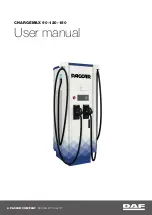
Fig. 5-1 2 C—I nsta 11 i n g S u p p o rt Plate on Pow er Piston
tube down, in a tool, fabricated from a piece of w ood, 2"
x 4" x 8" long with a 1-3/8" h ole in the center, clam ped
in a vise.
18. W ith Snap R ing Pliers J-4880, assem ble snap ring
into groove in air valve.
19. Place air valve spring retainer on snap ring.
A ssem ble reaction bum per into groove in end o f air valve.
20. Position air valve return spring, large end down,
on spring retainer.
21. The three reaction levers are now placed into
position with ears on w ide end in slots in power piston. The
narrow ends w ill rest on top o f air valve return spring.
22. Position reaction plate (with num bered side up) on
top o f reaction levers. Press down on plate until large ends
o f reaction levers pop up so plate rests flat on levers. Be sure
reaction plate is centered.
23. M aster cylinder piston rod and reaction retainer
assembly is now assem bled to the power piston.
24. W ith round end o f piston rod up, and with reaction
retainer held toward top o f piston rod, place small end o f
piston rod in hole in center o f reaction plate. Line up ears
on reaction retainer w ith notches in power piston and push
reaction retainer down until ears seat in notches.
25. M aintain pressure on reaction retainer and position
large lock ring dow n over master cylinder push rod.
26. There is a lug on the power piston w hich has a
raised divider in the center. O ne end o f lock ring goes under
lug and on one side o f divider.
27. A s you work your way around pow er piston (either
w ay), the lock ring goes over ear o f reaction retainer, under
a lug on power piston, and so forth, until other end o f lock
ring is seated under lug w ith raised divider.
Be sure both ends o f lock ring are securely under large
lug.
R ear Housing G roup A ssem bly
1. Place a new power piston bearing in center o f rear
housing so flange on center hole o f housing fits into groove
o f power piston bearing. The large flange on power piston
bearing w ill be on stud side o f housing.
2. Coat inside o f power piston bearing w ith D elco
Power Brake Lube (or equivalent).
Final Assembly
1. Place air silencer over holes on tube o f power piston.
W ipe tube o f power piston with D elco Power Brake Lube
(or equivalent).
2. A ssem ble power piston to rear housing.
3. W ipe tube o f reaction retainer with D elc o Pow er
Brake Lube (or equivalent) and lay assem bly aside.
4. Place front housing in a vise. Place power piston
return spring over the insert in the front housing. Lubricate
the I.D . o f the support plate seal with power brake lube or
equivalent.
5. Lightly lubricate beaded edge o f the diaphragm with
Pow er Brake Lube (or equivalent). H old rear housing and
power piston assem bly over front housing with m aster
cylinder push rod down. Position rear housing so that when
rotated into locked position, scribe marks on the housings
w ill be in line.
6. U sing H older J-22805-01 and W rench J-9504-01
lock housings together. Stake housing interlocks at 2 new
SUPPORT
PLATE
POWER
PISTON
SUPPORT PLATE
REMOVER AND
INSTALLER J-21524
O V E R H A U L M A N U A L
Summary of Contents for 1977 Monte Carlo
Page 1: ...CHEVROLET ST 333 80...
Page 4: ......
Page 6: ......
Page 50: ......
Page 70: ......
Page 100: ...4B 32 REAR AXLE DIFFERENTIAL Fig 24F lnstalling Pinion Flange OVERHAUL M AN U AL...
Page 126: ......
Page 136: ......
Page 142: ...5 6 BRAKES Fig 5 1 1A Gaging Piston Rod OVERHAUL M AN U AL...
Page 168: ......
Page 248: ......
Page 402: ...7C 6 CLUTCHES Fig 7 C 1 2 E D e p r e s s in g L ever Fig 7 C 1 4 E S ta k in g N u t...
Page 404: ......
Page 414: ......
Page 420: ......
Page 421: ......
Page 422: ......
Page 423: ......
Page 424: ......
Page 427: ......
Page 428: ......