Chapter 7
7-34
If all is normal, the toner supply motor (M8 through M11) rotates clockwise (CW). If something goes wrong and the motor rotates counterclockwise (CCW), how-
ever, the toner supply feedscrew will rotate to cause a change in the output of PS3 through (with the machine assuming malfunction of the toner supply motor).
E021-0000: Y/M development motor error
E021-0001: C/Bk development motor error
Any of the foregoing errors will be identified if a motor ready state fails to occur 3 sec or more after the start of the development motor.
E021-0100: Y/M development motor error
E021-0101: C/Bk development motor error
Any of the foregoing errors will be identified if a motor ready state remains for 3 sec or more while the development motor is at rest.
3. Toner recovery control
In the case that piezo sensor detects the toner absence, it executes toner recovery control when; installing machine, activating machine power (in the case of detecting
toner absence), the front door (of the machine) is opened, and during image formation (in the case of detecting toner absence).
Toner recovery control makes the stirring plate (inside TCRG) rotate (drive) for a specified time, and also makes the toner (inside TCRG) transfer inside of the
hopper. Thanks to this control, the toner density (inside the hopper) is stabilized, and the toner inside TCRG can be efficiently used up
7.6.3 Detecting the Level of Toner
0014-0773
/ / / / iR C3380i / iR C3380 / iR C2880i / iR C2880
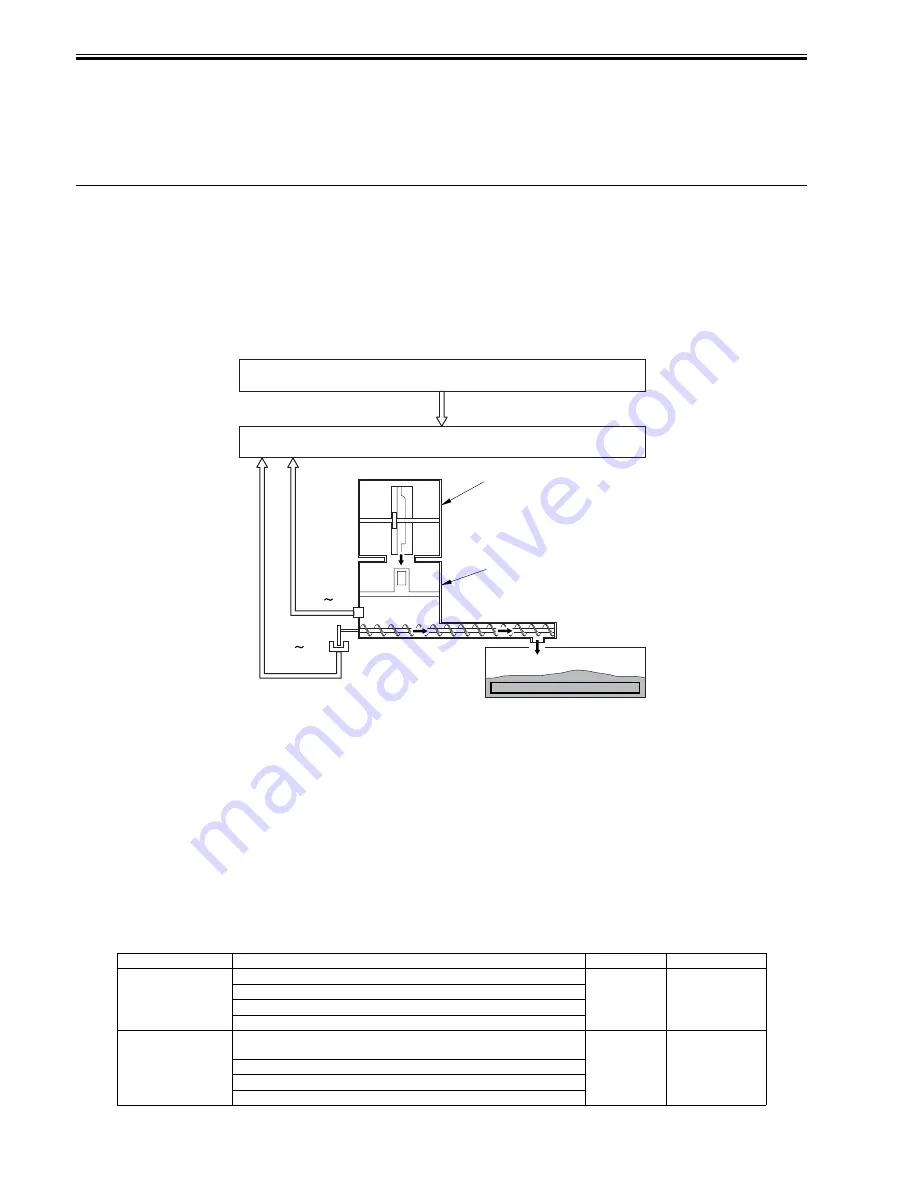
To detect the toner residual level of the hopper assembly for each color, this machine uses the following two kinds of detecting methods.
- Detection by the piezosensor
- Detection by toner refill quantity detection sensor
F-7-45
[1] Hopper assembly
[2] Toner detection signal
[3] Toner refill quantity detection signal
[4] drum unit
[5] toner container
TS1 through TS4: toner sensor (piezoelectric sensor)
PS3 to PS6: Toner feed level sensor
1. Detection by piezosensor
This is the detection for the presence or absence of the toner on the hopper assembly by the piezoelectric-vibrating piezosensor (TS1~4) mounted on the lower area
of the hopper assembly. It is executed at power ON, after the hopper assembly feeding and during the toner recovery control (hopper assembly forced feeding).
Piezosensor executes one set (sixteen times of reading) and judges the toner presence/absence based on the toner ratio at that time.
Toner absence: When the read value is judged as toner absence twelve times or more out of sixteen times
Toner presence: When judged as toner absence eight times or less out of sixteen times
The result of this detection is sent to DC control roller.
If the toner residual level is less than the specified value, DC controller notices two kinds of messages (toner absence notice, toner absence) to video controller.
The following is the relationship between the display message and the toner residual level.
T-7-14
Message type
Message Descriptio
Toner Level
Detected by:
Toner absence notice
"Black toner is low. Replacement not yet needed."
5%
video count
"Yellow toner is low. Replacement not yet needed. "
"Magenta toner is low. Replacement not yet needed."
"Cyan toner is low. Replacement not yet needed."
Abcence of toner
"Replace toner container. (Black)"
0%
piezo sensor
"Replace toner container. (Yellow) "
"Replace toner container. (Magenta) "
"Replace toner container. (Cyan) "
[4]
[5]
[1]
[2]
[3]
TS1 TS4
M-CON
D-CON
PS3 PS6
Summary of Contents for iR C3380 series
Page 1: ...Aug 29 2006 Service Manual iR C3380 2880 Series...
Page 2: ......
Page 6: ......
Page 23: ...Chapter 1 Introduction...
Page 24: ......
Page 26: ......
Page 52: ......
Page 53: ...Chapter 2 Installation...
Page 54: ......
Page 127: ...Chapter 3 Basic Operation...
Page 128: ......
Page 130: ......
Page 136: ......
Page 137: ...Chapter 4 Main Controller...
Page 138: ......
Page 160: ......
Page 161: ...Chapter 5 Original Exposure System...
Page 162: ......
Page 188: ...Chapter 5 5 24 F 5 68 4 Remove the original sensor 2 hook 1 F 5 69...
Page 189: ...Chapter 6 Laser Exposure...
Page 190: ......
Page 192: ......
Page 206: ......
Page 207: ...Chapter 7 Image Formation...
Page 208: ......
Page 256: ......
Page 257: ...Chapter 8 Pickup Feeding System...
Page 258: ......
Page 262: ......
Page 303: ...Chapter 9 Fixing System...
Page 304: ......
Page 306: ......
Page 321: ...Chapter 10 Externals and Controls...
Page 322: ......
Page 326: ......
Page 336: ...Chapter 10 10 10 F 10 10 2 Remove the check mark from SNMP Status Enabled...
Page 337: ...Chapter 10 10 11 F 10 11...
Page 359: ...Chapter 11 MEAP...
Page 360: ......
Page 362: ......
Page 401: ...Chapter 12 RDS...
Page 402: ......
Page 404: ......
Page 411: ...Chapter 13 Maintenance and Inspection...
Page 412: ......
Page 414: ......
Page 416: ...Chapter 13 13 2 F 13 1 8 9 1 2 3 3 5 6 7 10 11 12 13 14 4...
Page 421: ...Chapter 14 Standards and Adjustments...
Page 422: ......
Page 424: ......
Page 431: ...Chapter 15 Correcting Faulty Images...
Page 432: ......
Page 434: ......
Page 459: ...Chapter 16 Self Diagnosis...
Page 460: ......
Page 462: ......
Page 481: ...Chapter 17 Service Mode...
Page 482: ......
Page 484: ......
Page 571: ...Chapter 18 Upgrading...
Page 572: ......
Page 574: ......
Page 603: ...Chapter 19 Service Tools...
Page 604: ......
Page 606: ......
Page 609: ...Aug 29 2006...
Page 610: ......


