Chapter 2
2-29
2.11 Installing the Cassette Heater
2.11.1 Points to Note at Installation
0014-2976
iR C3380
- In the case of mounting the cassette heater unit to the cassette of the host machine, the heater PCB needs to be mounted.
- In the case of mounting the cassette heater unit to the cassette pedestal, the heater PCB and the cassette heater attachment need to be mounted.
2.11.2 Checking the Parts
0014-2690
/ / / / iR C3380i / iR C3380 / iR C2880i / iR C2880
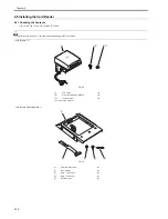
Prepare the following parts because each part of the heater PCB is assigned as service part.
F-2-91
T-2-2
2.11.3 Checking the Parts
0014-2775
/ / / / iR C3380i / iR C3380 / iR C2880i / iR C2880
Prepare the following parts because each part of the heater PCB is assigned as service part.
F-2-92
T-2-3
2.11.4 Turning Off the Host Machine
0014-2492
/ / / / iR C3380i / iR C3380 / iR C2880i / iR C2880
How to Turn Off the Main Power
When turning off the main power, be sure to go through the following steps to protect the hard disk:
1) Hold down the control panel power switch for 3 sec or more.
2) Follow the instructions on the shutdown sequence screen to let the main power switch be ready to turn off.
3) Turn off the power switch.
4) Disconnect the power cables (for the power outlet).
No.
Name
Part No.
Qty.
[1]
Heater Unit
FK2-0376-000
1pc
[2]
Plastic film
FC5-6899-000
1pc
[3]
Screw (binding; M4X6)
XB1-2400-607
1pc
No.
Name
Part No.
Qty.
[1]
Heater PCB
FM2-9979-000
1 pc
[2]
Screw (TP; M3X6)
XB6-7300-607
2 pc
[2]
[3]
[1]
[1]
[2]
Summary of Contents for iR C3380 series
Page 1: ...Aug 29 2006 Service Manual iR C3380 2880 Series...
Page 2: ......
Page 6: ......
Page 23: ...Chapter 1 Introduction...
Page 24: ......
Page 26: ......
Page 52: ......
Page 53: ...Chapter 2 Installation...
Page 54: ......
Page 127: ...Chapter 3 Basic Operation...
Page 128: ......
Page 130: ......
Page 136: ......
Page 137: ...Chapter 4 Main Controller...
Page 138: ......
Page 160: ......
Page 161: ...Chapter 5 Original Exposure System...
Page 162: ......
Page 188: ...Chapter 5 5 24 F 5 68 4 Remove the original sensor 2 hook 1 F 5 69...
Page 189: ...Chapter 6 Laser Exposure...
Page 190: ......
Page 192: ......
Page 206: ......
Page 207: ...Chapter 7 Image Formation...
Page 208: ......
Page 256: ......
Page 257: ...Chapter 8 Pickup Feeding System...
Page 258: ......
Page 262: ......
Page 303: ...Chapter 9 Fixing System...
Page 304: ......
Page 306: ......
Page 321: ...Chapter 10 Externals and Controls...
Page 322: ......
Page 326: ......
Page 336: ...Chapter 10 10 10 F 10 10 2 Remove the check mark from SNMP Status Enabled...
Page 337: ...Chapter 10 10 11 F 10 11...
Page 359: ...Chapter 11 MEAP...
Page 360: ......
Page 362: ......
Page 401: ...Chapter 12 RDS...
Page 402: ......
Page 404: ......
Page 411: ...Chapter 13 Maintenance and Inspection...
Page 412: ......
Page 414: ......
Page 416: ...Chapter 13 13 2 F 13 1 8 9 1 2 3 3 5 6 7 10 11 12 13 14 4...
Page 421: ...Chapter 14 Standards and Adjustments...
Page 422: ......
Page 424: ......
Page 431: ...Chapter 15 Correcting Faulty Images...
Page 432: ......
Page 434: ......
Page 459: ...Chapter 16 Self Diagnosis...
Page 460: ......
Page 462: ......
Page 481: ...Chapter 17 Service Mode...
Page 482: ......
Page 484: ......
Page 571: ...Chapter 18 Upgrading...
Page 572: ......
Page 574: ......
Page 603: ...Chapter 19 Service Tools...
Page 604: ......
Page 606: ......
Page 609: ...Aug 29 2006...
Page 610: ......


