Chapter 2
2-1
2.1 Making Pre-Checks
2.1.1 Selecting the Site of Installation
0013-8396
/ / / / iR C3380i / iR C3380 / iR C2880i / iR C2880
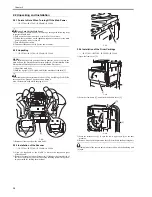
Select the site of installation against the following requirements; if possible, visit the user's before delivery of the machine:
1) There must be a power outlet properly grounded and rated as indicated (+, -10%) for exclusive use by the machine.
2) The environment of the room must be as indicated in the following diagram, and the machine must not be installed near a water faucet, water boiler, humidifier,
or refrigerator:
F-2-1
<Assured environmental zone>
[A]: A zone. All quality standard items are satisfied.
[B]: B zone. Some quality standard items are inferior to those in A zone or not satisfied.
[C]: C zone. Copying operation is performed normally without any safety issues, malfunction, and errors in display.
3) The machine must not be installed near a source of fire or in an area subject to dust or ammonium gas.
If the area is exposed to direct rays of the sun, provide curtains to the window.
4) The room must be well ventilated. (The level of ozone generated by the machine in use will not affect the individuals around it. However, some may find its odor
to be unpleasant, as when working in a poorly ventilated room.)
5) The floor of the machine must be level so that the feet of the machine will remain in contact and the machine will remain level.
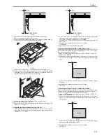
6) The machine must be at least 100 mm away from any wall, permitting unobstructed use.
Without accessory
F-2-2
100
(%RH)
(degC)
90
85
75
70
50
20
25
15
10
5
0
10
7.5
23
27.5
32.5
15
20
25
30
35
40
[A]
[B]
[C]
40 3/4" (1,035 mm)
4" (100 mm) or more
49" (1,243 mm )
Summary of Contents for iR C3380 series
Page 1: ...Aug 29 2006 Service Manual iR C3380 2880 Series...
Page 2: ......
Page 6: ......
Page 23: ...Chapter 1 Introduction...
Page 24: ......
Page 26: ......
Page 52: ......
Page 53: ...Chapter 2 Installation...
Page 54: ......
Page 127: ...Chapter 3 Basic Operation...
Page 128: ......
Page 130: ......
Page 136: ......
Page 137: ...Chapter 4 Main Controller...
Page 138: ......
Page 160: ......
Page 161: ...Chapter 5 Original Exposure System...
Page 162: ......
Page 188: ...Chapter 5 5 24 F 5 68 4 Remove the original sensor 2 hook 1 F 5 69...
Page 189: ...Chapter 6 Laser Exposure...
Page 190: ......
Page 192: ......
Page 206: ......
Page 207: ...Chapter 7 Image Formation...
Page 208: ......
Page 256: ......
Page 257: ...Chapter 8 Pickup Feeding System...
Page 258: ......
Page 262: ......
Page 303: ...Chapter 9 Fixing System...
Page 304: ......
Page 306: ......
Page 321: ...Chapter 10 Externals and Controls...
Page 322: ......
Page 326: ......
Page 336: ...Chapter 10 10 10 F 10 10 2 Remove the check mark from SNMP Status Enabled...
Page 337: ...Chapter 10 10 11 F 10 11...
Page 359: ...Chapter 11 MEAP...
Page 360: ......
Page 362: ......
Page 401: ...Chapter 12 RDS...
Page 402: ......
Page 404: ......
Page 411: ...Chapter 13 Maintenance and Inspection...
Page 412: ......
Page 414: ......
Page 416: ...Chapter 13 13 2 F 13 1 8 9 1 2 3 3 5 6 7 10 11 12 13 14 4...
Page 421: ...Chapter 14 Standards and Adjustments...
Page 422: ......
Page 424: ......
Page 431: ...Chapter 15 Correcting Faulty Images...
Page 432: ......
Page 434: ......
Page 459: ...Chapter 16 Self Diagnosis...
Page 460: ......
Page 462: ......
Page 481: ...Chapter 17 Service Mode...
Page 482: ......
Page 484: ......
Page 571: ...Chapter 18 Upgrading...
Page 572: ......
Page 574: ......
Page 603: ...Chapter 19 Service Tools...
Page 604: ......
Page 606: ......
Page 609: ...Aug 29 2006...
Page 610: ......


