background image

BÜCHI Labortechnik AG

Installation | 5

Operation Manual Interface I-300 Pro

35/102

The laboratory equipment to be evacuated is connected to the vacuum pump and the
VacuBox by means of vacuum tubing. See Chapter 5.2.5 "Overview: setting up vac-
uum tubing connections", page 37.

5.2.1

Connecting communication cables to interface unit

The communication connections between the Interface I-300 Pro, the VacuBox and
the other BUCHI laboratory equipment are established using the standard BUCHI
communication cable (green cable). The corresponding connection sockets are on
the rear panels of the devices and are marked "COM" for identification. Details of the
precise positions of the connection sockets are provided in the operating instructions
for the devices.

—

For connection options on the Interface I-300 Pro see Chapter 3.5.2 "Rear view",
page 15.

—

For connection options on the VacuBox see Chapter 3.5.3 "VacuBox (connec-
tions)", page 16.

5.2.2

Establishing LAN connection

Requirements for local network settings

u

The following port has to be enabled in the firewall settings on the internet gate-
way:

—

TCP (HTTPS) traffics through remote port 443

u

In order to use the BUCHI Cloud a DNS server must be configured on the instru-
ment.

NOTE

If there is no DNS server available enter the IP address for the BUCHI Cloud connec-
tion manually.

NOTE

If there is no DHCP server available enter the IP address, gateway subnet mask and
DNS server manually.

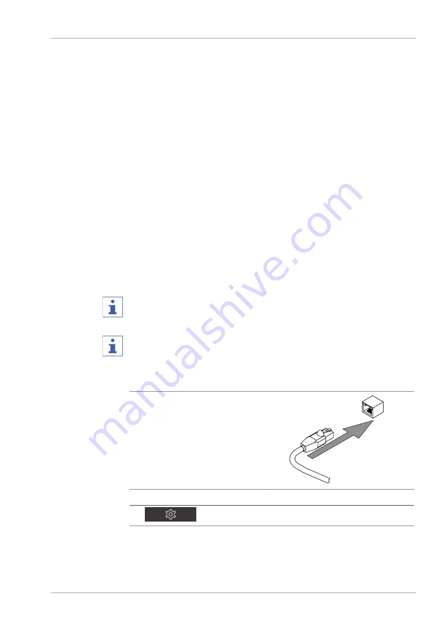
Preparing the instrument for app using

NOTICE! Do not unplug the LAN cable
while the unit is connected to the
BUCHI Cloud Services.

u

Connect the unit to the LAN (local
area network).

u

Restart the unit.

Navigation path


[Settings]


[Network]

u

Navigate to 

[Network]

.

Summary of Contents for Interface I-300

Page 1: ...Interface I 300 Pro Operation Manual STOP 11593781 E en ...

Page 2: ... right to make changes to the manual as deemed necessary in the light of experi ence especially with respect to structure illustrations and technical details This manual is copyrighted Information from it may neither be reproduced distributed or used for com petitive purposes nor made available to third parties The manufacture of any component with the aid of this manual without prior written agre...

Page 3: ...r R 300 and Rotavapor R 220 Pro controller 10 3 3 1 Control of R 300 and R 220 Pro 10 3 3 2 Parameter display with R 300 and R 220 Pro 12 3 4 Description of function for control of the R 300 with and without interface unit VacuBox 12 3 5 Configuration 14 3 5 1 Front view 14 3 5 2 Rear view 15 3 5 3 VacuBox connections 16 3 5 4 LegacyBox connections 17 3 5 5 Display 19 3 5 6 Type plate 20 3 6 Navig...

Page 4: ...nsor optional accessory 39 5 4 Connecting foam sensor optional accessory 40 5 5 Connecting valve unit for external vacuum 42 5 6 Operating I 300 and I 300 Pro in parallel 42 6 Operation 44 6 1 Navigating the menu 44 6 1 1 Selecting menu items 44 6 1 2 Entering parameter settings 45 6 1 3 Changing settings 47 6 2 Performing distillation 47 6 2 1 Overview typical distillation sequence 48 6 2 2 Basic...

Page 5: ...ults 86 8 1 Faults possible causes and remedies 86 8 2 Error messages 86 8 3 Customer service 86 8 4 eSupport 87 9 Taking out of service and disposal 88 9 1 Taking out of service 88 9 2 Disposal 88 10 Appendix 89 10 1 Solvent table 89 10 2 Spare parts and accessories 90 10 2 1 Accessories 90 10 2 2 Wearing parts 93 10 2 3 Spare parts 93 10 3 Health and safety approval 94 10 4 Health and safety 94 ...

Page 6: ...Signal word Meaning DANGER Indicates a danger with a high level of risk which could result in death or serious injury if not prevented WARNING Indicates a danger with a medium level of risk which could result in death or serious injury if not prevented CAUTION Indicates a danger with a low level of risk which could result in mi nor or medium severity injury if not prevented NOTICE Indicates a dang...

Page 7: ...ike this Field names Field names are marked up like this Menu Menu item Menus or menu items are marked up like this Status Status is marked up like this Signal Signals are marked up like this 1 3 Trademarks Product names and registered or unregistered trademarks that are used in this docu ment are used only for identification and remain the property of the owner in each case ...

Page 8: ... that intended In particular the following applications are not permissible Use of the device in areas that require apparatus that is safe to use in potentially explosive atmospheres Use as a calibration device for other equipment Operation at pressures above atmospheric Damage or hazards attributable to use of the product other than as intended are en tirely at the risk of the user alone 2 3 Staf...

Page 9: ...s used incorrectly Appropriate warnings in this manual serve to alert the user to these residual dangers 2 4 1 Faults during operation If a device is damaged sharp edges moving parts or exposed electrical wires can cause injuries u Regularly check device for visible damage u If faults occur switch off the device immediately unplug the power cord and in form the operator u Do not continue to use de...

Page 10: ...the associated VacuBox Measurement is independent of the solvent used 3 2 Description of function Cloud Services Option Dongle LAN App System owner X X X X X x X X X x X X X Option NOTE 4 For update details see Firmware Update Quick Guide 4 For details of Monitor app see BUCHI Monitor App Quick Guide 4 For details of eSupport see Chapter 8 4 eSupport page 87 4 For details of OpenInterface see Chap...

Page 11: ...e Chap ter 6 2 3 Executing Manual mode page 50 Distillation carried out with man ually set parameters See Chap ter 6 2 3 Executing Manual mode page 50 Timer mode Distillation carried out with man ually set parameters See Chap ter 6 2 4 Executing Timer mode page 53 Distillation carried out with man ually set parameters See Chap ter 6 2 4 Executing Timer mode page 53 Continuous pumping For drying th...

Page 12: ...o different parameters may be shown Below is a comparison of the R 300 and R 220 Pro Rotavapors Parameter Information R 300 R 220 Pro Vacuum Current system pressure Desired system pressure Rotation Current rotation speed Desired rotation speed Heating bath Current heating bath temperature Desired heating bath temperature Recirculating chiller Current system temperature Desired system temperature V...

Page 13: ...e Required temperature set us ing control knob on heating bath base Current and set temperature shown on display home screen of interface unit and on heating bath base Required temperature set us ing control knob on heating bath base Recirculating chiller temper ature Current coolant temperature shown on display on device Required temperature set us ing control knob on device Current system temper...

Page 14: ...BÜCHI Labortechnik AG 14 102 Operation Manual Interface I 300 Pro 3 5 Configuration 3 5 1 Front view STOP 1 2 3 Fig 1 Front view of Interface I 300 Pro 1 Touch screen display 3 Navigation control 2 STOP button emergency stop ...

Page 15: ... Manual Interface I 300 Pro 15 102 3 5 2 Rear view 2 3 1 4 6 5 Fig 2 Rear view of Interface I 300 Pro 1 LAN port 4 Slot for BUCHI SD card 2 BUCHI standard communication port COM 5 USB connection not used 3 Locating lug for bracket 6 MicroSD card not used ...

Page 16: ... Fig 3 Connections on the VacuBox 1 Vacuum connection 5 Connection for vapor temperature Au toDest sensor VT AS 2 Venting valve inert gas connection optional 6 Foam sensor connection FS 3 Water coolant valve connection CW 7 Standard BUCHI communication port COM 4 Connection for valve unit or straight way valve VALVE NOTE Connecting VacuBox with R 220 Pro If the Interface I 300 Pro and the VacuBox ...

Page 17: ...mp 2 4 3 1 6 5 Fig 4 Connections on the LegacyBox 1 Standard BUCHI communication port COM 4 RS 232 not used 2 0 10 V communication port for connecting pumps of other makes 5 External power supply for genuine BUCHI mains adaptor 30 V 30 W see Accessories 3 RS 485 communication port for connecting legacy BUCHI laboratory equipment Vacuum Pumps V 700 V 710 Rotavapors R 210 R 215 Recirculating Chiller...

Page 18: ... of socket Pin 8 pin notation Symbol Description 1 Ground Ground connection for valve and 10 V output 2 Valve Vacuum valve connection 3 Spare 4 10 V output 0 10 V max 20 mA min 500 Ohm 5 Relay In Max 30 V 2 A electrically isolated 6 Spare 7 Spare 8 Relay Out Max 30 V 2 A electrically isolated S Shield Shield connected to ground ...

Page 19: ... g vacuum 2 Menu bar 7 Direct intervention buttons 3 Current reading e g vacuum 8 Scroll bar 4 Lift position 9 Lift control 5 Function buttons context dependent 10 Graph display area NOTE While distillation is in progress the display is shown in inverse type A progress bar for each process parameter shows the status on reaching the specified setting con cerned ...

Page 20: ... name 8 Country of manufacture 3 Serial number 9 Approvals 4 Input voltage 10 Symbol for Do not dispose of as household waste 5 Frequency 11 Product code 6 Maximum power rating NOTE The VacuBox and the LegacyBox each have their own type plate on the rear 3 6 Navigating through the menu system 3 6 1 Menu bar The menus are represented by symbols on the menu bar The following menus are available Symb...

Page 21: ...g Drying the system after distillation See Chapter 6 2 5 Ex ecuting Continuous Pumping mode page 57 AutoDest Carrying out automatic single or multi stage distillation with specified settings for the vacuum continuously adjusted by the system See Chapter 6 2 6 Ex ecuting AutoDest mode page 59 Drying Post drying of contents of evaporating flask This feature is only available in conjunction with the ...

Page 22: ...ion of distillation On start start rota tion On Off Evaporating flask starts rotating when distillation is started On finish Stop ro tation On Off Evaporating flask stops rotating after au tomatic or manual termination of distilla tion On start immerse flask On Off Evaporating flask is automatically im mersed in the heating bath when distilla tion is started On finish lift out flask On Off Evapora...

Page 23: ...Temperature unit Choice of unit for indication of tem peratures C Celsius F Fahrenheit or K Kelvin Pressure Unit Choice of unit for indication of nega tive pressure hPa hectopascals mbar millibars torr mmHg mmHg millimeters of mer cury Height above sea level Enter value Altitude of location above mean sea level Max 4000 m For determination of max allowable pressure when working with the solvent li...

Page 24: ...u BUCHI Cloud Services contains functions and views relating to cloud solutions Action Option Explanation System owner Info Shows the details of the registered sys tem owner The details of the system owner are transferred from the connected app and can be edited there See BUCHI Cloud and Monitoring Services Quick Guide eSupport Status Shows the status of an eSupport re quest See Chapter 8 4 eSuppo...

Page 25: ...y calibration page 84 System Information submenu The submenu System information contains details of the currently connected labora tory equipment and information on network connection diagnosis 3 6 5 Libraries menu Action Option Explanation Solvent library Select The solvent library item izes the commonly used solvents in alphabetical or der Own solvent library For creating your own sol vent libra...

Page 26: ...x 50 x 221 mm Dimensions W x D x H Shipping box 300 x 85 x 340 mm Weight 600 g Power consumption 10 W Power supply voltage 30 VDC 5 Display Protection class IP21 Approvals CE CSA 3 8 2 Junction boxes VacuBox LegacyBox Dimension W x D x H 50 x 57 x 167 mm 50 x 28 x 167 mm Weight 400 g 200 g Measurement range 1300 0 mbar Measurement range Ambient pressure 0 mbar Measuring accuracy 2 mbar after calib...

Page 27: ...nt conditions Max altitude above sea level 2000 m Ambient temperature 5 40 C Maximum relative humidity 80 for temperatures up to 31 C decreasing linearly to 50 at 40 C The laboratory equipment described in this document may only be used in indoor ar eas 3 8 4 Materials Component Material Pressure foil Polyester Casing PBT Vent tube connection PPS Pressure sensor Al O 96 ...

Page 28: ...kage ideally in the original box u Avoid sharp movements during transit u After transportation check the device for damage u Damage that has occurred in transit should be reported to the carrier u Keep packing for future transportation 4 2 Storage u Make sure that the ambient conditions are complied with see Chapter 3 8 Tech nical data page 26 u Wherever possible store the device in its original p...

Page 29: ...nd see Chapter 5 1 4 Mounting interface unit on laboratory stand optional acces sory page 33 5 1 1 Mounting interface on Rotavapor R 300 The Interface I 300 Pro can be mounted and connected up on the vertically ad justable arm of the Rotavapor R 300 Tools required Torx keys Tx20 and Tx30 1 3 2 Fig 7 Handle of Rotavapor R 300 1 Cover 3 Fixing screw for cover 2 Communication cables u Remove the scre...

Page 30: ... for the interface unit on the Rotavapor arm 6 At the same time feed the communication cable through the bottom hole in the holder u Fix the holder to the Rotavapor arm with a screw 4 When doing so pass the screw through the hole in the metal plate 5 u Connect the communication cable to the COM port on the rear of the interface unit u Position the interface unit 3 on the holder and fix it in place...

Page 31: ...p of the Vacuum Pump V 300 using a holder u Remove the rubber plug 4 from the top panel of the vacuum pump Use a screw driver if necessary ð Underneath the rubber plug is a threaded hole for a screw u Position the holder 7 over the threaded hole 4 and fix it in place using the screw 2 supplied When doing so pass the screw through the hole in the metal plate 3 u Feed the communication cable through...

Page 32: ... with a standard BUCHI communication connection and a LAN cable u Position metal plate on back of Interface I 300 Pro and screw in place u Connect Rotavapor communication cable to the interface unit u Connect Rotavapor LAN cable to the interface unit For a network connection there must be a connection from the rear panel of the Rotavapor to a network u Insert the interface unit into the recess nex...

Page 33: ... 1 on the laboratory stand 3 and fix it in place using the T screw 5 u Position the interface unit 2 on the flat face 1 of the holder and fix it in place us ing a knurled head screw 4 5 1 5 Mounting interface unit on a wall bracket optional accessory STOP 1 2 3 4 6 5 Fig 11 Two piece wall bracket for interface unit 1 Front plate of wall bracket 4 Rear plate of wall bracket 2 Interface unit 5 Slot ...

Page 34: ...n the rear plate and then press the front plate down 5 2 Connecting the Interface I 300 I 300 Pro The Interface I 300 I 300 Pro can be connected either to an individual BUCHI labora tory device or to a complete distillation system 3 4 5 1 3 4 5 1 Fig 12 Interface unit VacuBox Rotavapor vacuum pump and recirculating chiller 1 Recirculating Chiller F 3xx 4 Vacuum Pump V 300 2 Rotavapor R 300 with He...

Page 35: ...he devices For connection options on the Interface I 300 Pro see Chapter 3 5 2 Rear view page 15 For connection options on the VacuBox see Chapter 3 5 3 VacuBox connec tions page 16 5 2 2 Establishing LAN connection Requirements for local network settings u The following port has to be enabled in the firewall settings on the internet gate way TCP HTTPS traffics through remote port 443 u In order t...

Page 36: ... a VacuBox also has to be connected Below is an example of the connections between the laboratory apparatus Recirculating Chiller Interface Destilation unit Vacuum Pump Vacu Box StatusLight Dongle Fig 13 Schematic diagram of communication connections between the BUCHI laboratory equipment example NOTE Connections on R 220 Pro Information on the connection of communication cables coolant and vacuum...

Page 37: ...d the inlet of the condenser on the Rotavapor R 300 3 u Connect a tube between the outlet of the condenser on the Rotavapor R 300 4 and the inlet of the secondary condenser on the Vacuum Pump V 300 5 u Connect a tube between the outlet of the secondary condenser on the Vacuum Pump V 300 6 and the inlet of the recirculating chiller 1 NOTE Connections on R 220 Pro Information on the connection of co...

Page 38: ... secondary condenser to the pump outlet 2 u For measuring and controlling the vacuum connect a tube between the inlet of the Woulff bottle marked CONTR 5 and the VacuBox 6 The pressure is measured in the VacuBox The current working pressure can be indi cated and controlled by means of the Interface I 300 I 300 Pro NOTE The VacuBox and Woulff bottle can be mounted either on the Rotavapor R 300 or t...

Page 39: ...peratures Temperature of the incoming coolant Temperature of the outgoing coolant Temperature of the vapor exiting the evaporating flask 1 3 6 4 2 5 Fig 16 AutoDest sensor vapor temperature sensor and cooling condenser with evaporating flask and receiving flask of a Rotavapor R 300 1 Vapor temperature sensor 4 Cooling condenser 2 AutoDest sensor 5 Coolant inlet on condenser 3 Communication connect...

Page 40: ...outgoing cable 3 from the AutoDest sensor to the VacuBox Use the connection marked VT AS for this lead NOTE There should be no air bubbles in the coolant as otherwise correct functioning of the AutoDest sensor is not guaranteed NOTE Installing automatic mode sensor on R 220 Pro The installation of the automatic mode sensor on the Rotavapor R 220 Pro is de scribed in the operating instructions of t...

Page 41: ... the tapered holder 4 over the upper end of the foam sensor 1 u Feed the foam sensor together with holder through the cooling condenser and the vapor duct into the evaporating flask of the Rotavapor R 300 and fix in place with the clamp nut When inserting the foam sensor make sure that the sensor rod passes centrally through the components The tip of the foam sensor should be positioned approx 4 t...

Page 42: ...t on laboratory stand optional accessory page 33 u Connect the vacuum valve to the VacuBox using a communication cable plugged into the connection marked VALVE u Connect vacuum tubing between the laboratory apparatus to be evacuated the VacuBox and the external vacuum unit u If a Rotavapor is not connected connect the VacuBox to the mains adaptor using an adaptor cable and plug the mains adaptor i...

Page 43: ...ction page 35 is desired when the I 300 and I 300 Pro are operating in parallel the LAN cable must only be connected to one of the interface units preferably the I 300 Pro u Connect the remote interface unit to the interface unit on the Rotavapor using the standard BUCHI communication port COM Use a standard BUCHI communica tion cable to do so ...

Page 44: ...n menu simply tap the desired symbol ð The selected menu icon is highlighted in green u To select a menu item from the submenu tap the desired menu item On some submenus the list of menu items is too long to be shown on the display all at once In that case a scroll bar appears on the right u To scroll down to a menu item on a submenu slowly swipe the screen upwards with your finger Fig 18 submenu ...

Page 45: ...red item is highlighted in green u Press the navigation control to choose OK and confirm the selection ð The display shows the desired submenu on the next menu level down u To return to the previous menu level press the function button u To return to the main menu press the MENU function button 6 1 2 Entering parameter settings The Interface I 300 Pro offers the facility for manually setting vario...

Page 46: ... increase or decrease the figure turn the navigation control clockwise or counter clockwise Alternatively enter the figure using the keyboard u To save the new setting press the navigation control to choose SAVE or tap SAVE directly on the screen ð The new parameter setting is shown highlighted in green again If a reading graph is displayed see Chapter 6 3 Displaying reading graphs page 67 not all...

Page 47: ... setting press the navigation control to choose EDIT or directly tap EDIT on the screen ð The options for the setting are shown u To select an option turn the navigation control or tap the option directly on the screen A green bar appears next to the selected option Fig 24 Options for a setting u To save the new option for the setting press the navigation control to choose SAVE or tap SAVE directl...

Page 48: ...process typically requires the following steps in the order indicated NOTE The steps listed below in Starting distillation and Stopping distillation can also be pre programmed via the interface unit see Configuration Starting distillation Step Component Action 1 Heating bath Set the required temperature and start the heating bath 2 Recirculating chiller Set the required temperature and start the r...

Page 49: ...uring distillation There is the possibility to briefly venting the system while distillation is in progress u To briefly vent the system while distillation is in progress press and hold the AER ATE function button until the desired pressure is reached ð While venting is active the status bar is shown in yellow on the display Fig 25 Home screen during venting u To evacuate the system to the specifi...

Page 50: ...ondition R After completion of distillation the system has been fully vented by pressing the AERATE function button u To manually stop the cooling process press the function button ð The cooling process is stopped and the cooling symbol disappears from the status bar Stopping everything There is the possibility to immediately stopping all apparatus connected to the system while distillation is in ...

Page 51: ...s for the process parameters In this operating mode the following parameters and readings are available Parameters and readings Equipment possibly required Specified setting for vacuum Actual reading for current pressure in distillation system VacuBox e g with Vacuum Pump V 300 V 600 Actual reading and specified setting for rotation speed evaporating flask Rotavapor R 300 Actual reading and specif...

Page 52: ...l for distillation in progress Fig 29 Distillation process started ð The actual readings are shown more brightly in the left hand column of the display The right hand column shows the specified settings u To abort the cooling process prematurely press the function button STOP Editing parameters during manual distillation There is the facility for changing individual parameter settings while distil...

Page 53: ... After the parameter setting has been altered the display shows the home screen in inverse type with the current readings displayed more brightly Stopping manual distillation u To stop the distillation process press the function button STOP ð The display shows the home screen with the current readings and specified set tings The status bar shows the cooling symbol if applicable together with a tim...

Page 54: ...this operating mode the following parameters and readings are available Parameters and readings Equipment possibly required Specified setting for vacuum Actual reading for current pressure in distillation system VacuBox e g with Vacuum Pump V 300 V 600 Actual reading and specified setting for rotation speed evaporating flask Rotavapor R 300 Actual reading and specified setting for heating bath tem...

Page 55: ...n the status bar The actual readings for the timer and the other parameters are shown in the left hand column of the display The right hand col umn shows the corresponding specified settings Editing timer and parameter settings while distillation is in progress There is the facility for changing the timer setting and other parameters while timer controlled distillation is in progress Precondition ...

Page 56: ...other parameters as necessary Stopping timer controlled distillation The timer controlled distillation process stops automatically when the preset time has elapsed After completion of timer controlled distillation an audible signal consisting of three beeps sounds at regular intervals if the corresponding option has been set on the Configuration menu NOTE The audible signal is canceled as soon as ...

Page 57: ...In Continuous pumping mode the system continues running in idling mode to dry out the vessels and tubing after a distillation process has finished NOTE In Continuous pumping mode the settings for manual or timer controlled distillation are ignored Navigation path Operating modes Continuous pumping Fig 37 Selecting the option Continuous pumping on the Operating modes menu ...

Page 58: ... and Recir culating chiller temperature Those processes cannot be started via the interface unit and instead have to be started manually on the equipment concerned u Select and edit the settings for individual process parameters as necessary u Press the function button START to start the drying process ð The drying process continues running until it is stopped manually Fig 39 Continuous pumping fo...

Page 59: ...t mode Automatic distillation requires the use of an AutoDest sensor The AutoDest sensor is connected to the VacuBox see Chapter 5 3 Connecting AutoDest sensor to vapor temperature sensor optional accessory page 39 and measures the inlet and outlet temperature of the coolant and the vapor temperature at the cooling condenser From those three readings the system calculates the parameter settings re...

Page 60: ...ating bath and coolant are set so as to be 40 C apart In this operating mode the following parameters and readings are available Parameters and readings Equipment possibly required Specified setting for vacuum Actual reading for current pressure in distillation system VacuBox e g with Vacuum Pump V 300 V 600 Actual reading and specified setting for rotation speed Rotavapor R 300 Actual reading and...

Page 61: ... parameters may only be altered gradually otherwise distillation may be aborted Stopping automatic distillation NOTE The distillation process stops automatically as soon as the solvent in the evaporating flask has evaporated There is the option for stopping distillation prematurely u To stop the automatic distillation process prematurely press the function button STOP ð The display shows the home ...

Page 62: ...s operating mode the rotation speed is limited to 150 rpm u Set the desired rotation interval for the evaporating flask by means of the process parameter Rotation interval u Set the desired length of the drying process by means of the process parameter Timer u To to start the process for drying the product press the function button START ð The process stops automatically when the preset time has e...

Page 63: ... 12 steps with defined times and parameters Up to 30 methods can be created In Methods op erating mode automatic distillation is not possible The following steps can be programmed Step Possible settings Gradient In this mode the following process parameters can be defined Initial vacuum Terminal vacuum Timer Rotation Heating bath Recirculating Chiller On start immerse flask On finish lift out flas...

Page 64: ...on Heating bath Recirculating Chiller On finish lift out flask On finish Aerate system Example Step 1 Gradient 300 mbar Step 2 Pause Message Fit dry receiving flask Step 3 Drying 150 rpm 5 minutes Creating a method Navigation path Operating modes Methods Fig 45 Selecting the option Methods on the Operating modes menu u Navigate to the Operating modes menu and select the menu item Methods see Chapt...

Page 65: ...t the menu item Step u Press EDIT u Select the menu item Function to assign a function u Save the assigned function by pressing SAVE ð The possible settings for the function concerned appear u Enter the desired settings u Press SAVE STEP to save the edited step u Define all the other steps as described above and then save the method by choos ing SAVE METHOD NOTE Any of the settings for a method ca...

Page 66: ...hod NOTE Graph display of specified settings When the method is created and selected the graph progression shows all specified settings of the programmed parameters The specified settings are displayed across all programmed steps u Select a method and press START to start the distillation process immediately Fig 50 Display while method is running ð The display shows the home screen in inverse type...

Page 67: ...ss data read ings while distillation is in progress You can individually select which process param eters are to be shown as graphs The following readings can be shown as graphs Actual vacuum Actual rotation speed Actual heating bath temperature Actual recirculating chiller temperature Actual vapor temperature Fig 51 Activating a graph Precondition R The home screen is displayed u To display the r...

Page 68: ...e Actual and specified rotation speed Actual and specified heating bath temperature Actual and specified recirculating chiller temperature Actual vapor temperature Events such as defoaming and AERATE Difference between inlet and outlet temperature at AutoDest sensor The data is saved as a TXT file in CSV format Recording starts every time a distilla tion process is started if the option has been s...

Page 69: ...n SD card STOP 2 1 Fig 54 Inserting SD card 1 Slot 2 BUCHI SD card u The BUCHI SD card is inserted in the slot in the interface unit as shown When do ing so make sure that the bevelled corner of the SD card is at the top right ð The display shows the symbol for SD card inserted on the status bar ...

Page 70: ...nal solvent library Stored in that library are the most common solvents together with an algorithm in each case Based on the chemi cal properties of the solvent the algorithm calculates and dynamically sets the ideal vacuum according to the current readings for heating bath and coolant temperature That means that the distillation process can be started immediately even if the ideal heating bath an...

Page 71: ...d the actual figures are automatically applied If equipment of a different make is connected the set tem peratures on the devices concerned have to be entered as specified settings on the interface NOTE Display of calculated values for solvent The calculated values for a solvent are based on the chemical properties of the cho sen solvent and the settings entered or readings communicated from the h...

Page 72: ...een the settings for the individual process pa rameters can be edited Fig 58 Editing the specified settings for the selected solvent on the home screen NOTE The temperatures for heating bath and coolant should be set so as to be 40 C apart 6 5 2 Creating your own solvent library You can also create your own solvent library in which you can enter details of up to 60 of your own solvents Navigation ...

Page 73: ...on system remains inactive for a predefined period of time In eco mode the distillation system shuts down the activity of the heating bath and recirculating chiller after a de fined delay period so that The heating bath does not reheat until the heating bath temperature has dropped to a defined minimum temperature The recirculating chiller does not re chill until the coolant temperature has risen ...

Page 74: ...ure regulation by the valve or the valve unit The hysteresis is the maximum allowed deviation of the vacuum from the speci fied setting before the system corrects the pressure The pump is switched off valve is closed when the vacuum has reached the lowest possible pressure If the pressure rises and the set hysteresis is exceeded the pump is switched on again the valve opened again Navigation path ...

Page 75: ...d settings as favorites bookmarks Fig 62 Submenu Favorites Clicking on any of the saved favorites takes you directly to the screen concerned Fig 63 Example of frequently used screen showing function button Add to favorites in bottom menu bar u Navigate to a frequently used screen on the interface unit u To add that screen to your favorites press the function button below the symbol ð The screen wi...

Page 76: ...e unit a depth stop has to be set For details refer to the Rotavapor operating instructions The home screen of the interface unit then shows the parameter Lift to gether with the actual position and the depth stop setting If the rotary drive unit is lowered into the heating bath as far as the depth stop the actual position is the same as the selected setting Using the interface unit the lift posit...

Page 77: ...nd preserve the warranty 7 1 Cleaning the casing display u Use a damp cloth to clean the device u To clean the casing only use ethanol or soapy water 7 2 Performing a leak test Use the leak test to check the system for leaks Navigation path Configuration Maintenance Leak test Precondition R All openings in the vacuum system are sealed u Navigate to the Maintenance screen and select the menu item L...

Page 78: ... Pro Fig 66 Display of leakage rate NOTE Typically an airtight system should have a leakage rate of less than 5 mbar min 7 3 Opening leak test history Use the function Test results to view details of leak tests previously carried out Navigation path Configuration Maintenance Test results ...

Page 79: ...uBox 1 Tube seal 3 Tubing 2 GL14 cap nut u Insert the tube seal 1 in the GL14 cap nut 2 ensuring it is straight NO TICE Risk of damaging tube seal Make sure that the tube seal does not twist or jam in the GL14 cap nut u Loosely screw the GL14 cap nut together with tube seal onto the device con cerned example shows VacuBox or the Woulff bottle u Carefully insert the end of the tube 3 into the GL14 ...

Page 80: ...ructions of the connected rotary evapo rator u Navigate to the Maintenance sub screen and select the menu item Reset rota tion hours see Chapter 6 1 Navigating the menu page 44 u When asked to confirm press OK ð The rotation hours are reset 7 7 Calibrating AutoDest sensor The AutoDest sensor measures the temperature of the coolant at the inlet and outlet of the cooling condenser Adjust the sensors...

Page 81: ... item AutoDest sensor see Navigating the menu u Press the navigation control to choose OK and confirm the calibration offset 7 8 Calibrating the pressure sensor The pressure sensor is calibrated at the factory by BUCHI prior to delivery However it can be recalibrated with the aid of an external reference pressure gauge at any time Navigation path Configuration Servicing u Navigate to the Configura...

Page 82: ...o as the offset The offset applies to the entire pres sure range Navigation path Configuration Servicing Pressure offset u Connect the reference pressure gauge to the same vacuum system that the pump and interface unit are connected to u Navigate to the Service screen and select the menu item Pressure offset see Chapter 6 1 Navigating the menu page 44 Fig 69 Menu item Pressure offset u Enter the p...

Page 83: ...on u Connect the reference pressure gauge to the same vacuum system that the pump and interface unit are connected to u Navigate to the Service screen and select the menu item Pressure calibration see Chapter 6 1 Navigating the menu page 44 Fig 70 Menu item Pressure calibration u In the first stage enter the pressure indicated by the reference pressure gauge u In the second stage use the function ...

Page 84: ...device asks you to confirm that the factory calibration should be reloaded Fig 71 Menu item Back to factory calibration u Press the function button OK to confirm or the function button ESC to retain the existing calibration settings 7 9 Setting up Rotavapor Open Interface Rotavapor Open Interface enables you to obtain an overall view of the status and communication of third party equipment with th...

Page 85: ...twork For connection details see Chapter 3 5 Configuration page 14 u Navigate to the Rotavapor Open Interface sub screen and select the option Yes see Chapter 6 1 Navigating the menu page 44 u Confirm the action when asked ð The interface shows the password u Restart the interface ð The Rotavapor Open interface unit is set up ...

Page 86: ...um is not achieved Back evaporation from the re ceiving flask u Empty receiving flask see Rotavapor operating instruc tions System is leaking u Check system for leaks see Rotavapor operating instruc tions u If necessary replace tubing and or seals Water pressure of glass filter pump is too low u Increase water flow see pump operating instruc tions Vacuum pump is too weak u Use suitably dimensioned...

Page 87: ...icket directly to a BUCHI technical engineer Navigation path Configuration BUCHI Cloud Services Precondition R The BUCHI Cloud Services have been installed and set up For details see BUCHI Cloud and Monitoring Services Quick Guide or https www buchi com en buchi cloud u Navigate to the BUCHI Cloud Services sub screen see Chapter 6 1 Navigat ing the menu page 44 ð The interface shows the current st...

Page 88: ...g out of service u Switch off the Interface I 300 Pro and disconnect it from the mains power supply u Remove all tubing and communication cables from the device 9 2 Disposal The operator is responsible for proper disposal of the Interface u When disposing of equipment observe the local regulations and statutory require ments regarding waste disposal ...

Page 89: ...H2Cl2 97 0 322 60 1 284 479 trans 1 2 dichloroethene C2H2Cl2 97 0 314 48 1 257 751 Di isopropyl ether C6H14O 102 0 318 68 0 724 375 Dioxane C4H8O2 88 1 406 101 1 034 107 DMF dimethylfor mamide C3H7NO 73 1 153 0 949 11 Acetic acid C2H4O2 60 0 695 118 1 049 44 Ethanol C2H6O 46 0 879 79 0 789 175 Ethylacetate C4H8O2 88 1 394 77 0 900 240 Heptane C7H16 100 2 373 98 0 684 120 Hexane C6H14 86 2 368 69 0...

Page 90: ... permission of BUCHI 10 2 1 Accessories Order no Image BUCHI Bluetooth Dongle connects instrument to smartphone via Bluetooth Needed for firmware updates and eSupport 11067770 StatusLight cpl incl communication cable Indicates the status of the instrument instrument is ready to use has an error or is in operation 11068959 AutoDest sensor Incl cap nut seal GL14 For automatic distillation Measures t...

Page 91: ...n cable RJ45 2 m Connection between vacuum controller interface and recirculating chiller or vacuum controller interface and vacuum pump 044989 Communication cable RJ45 5 m Connection between vacuum controller interface and recirculating chiller or vacuum controller interface and vacuum pump 11056240 Cooling water valve 24VAC Valve opens cooling water feed during distillation Meant to be used with...

Page 92: ... or vacuum controller when they cannot be mounted on a peripheral or wall 048891 Vacuum valve Magnetic valve 24V 4W Mini DIN 1 5 m Flow valve without flask meant to be used with a cen tralized vacuum source or an unregulated vacuum pump Meant to be used with the Interface I 300 I 300 Pro 11060706 Valve unit Incl Woulff bottle 125 mL P G holder Magnetic valve meant to be used with the Interface I 3...

Page 93: ...g set Hose barbs and seals GL14 Content Hose barbs bent 4 pcs hose barbs straight 1 pc cap nuts 4 pcs screw caps 2 pcs seals EPDM 3 pcs 11061921 Hose barbs set 4 pcs bent GL14 silicone seal Content Hose barbs cap nuts seals 037287 Hose barbs set 4 pcs straight GL14 silicone seal Content Hose barbs cap nuts seals 037642 Hose set Incl GL14 set FEP tube 11061756 Used to connect VacuBox and Valve unit...

Page 94: ...ations for handling hazardous materials for the purposes of health and safety at work and safe disposal of waste no products may be sent back to BÜCHI Labortech nik AG or repaired unless we have received the declaration below completed and signed Products sent to us will not be accepted for repair until we have received this declara tion u Copy the form overleaf and complete it u Make sure that yo...

Page 95: ...ogically active explosive ra dioactive or other hazardous materials are not contaminated The solvents or residues of the substances pumped have been removed Declaration for haz ardous materials In respect of the products returned we hereby assure that all substances toxic corrosive biologically active explosive radioactive or other wise hazardous that have been pumped by the products or have other...

Page 96: ...sages that appear as pop ups on the display e g Distillation successfully completed Event message ID Event message level information warning or error On occurrence Event messages are managed by the server and distributed to the clients from there for push notifications Process data Actual reading and specified setting for pressure Actual reading and specified setting for heating bath temperature A...

Page 97: ...ion Permanent Client data inc date and time of last connection At most 1 year after last use Status data Event data Process data At least 24 hrs max 48 hrs Data that is older than 24 hrs is deleted after 24 hrs Data configuration settings Destination host connect buchi com Destination port 443 Protocol HTTPS TLS 1 2 Certificates RSA 2048 bit SHA 256 Server location Ireland operator Amazon Web Ser ...

Page 98: ...e data All maintenance tests showing details of results and progression 10 5 7 System configuration data System name Article numbers Serial number Firmware versions Parts list version Instruments installed in the system Sensors installed in the system 10 5 8 Distillation process data All process data that is required for running a distillation process e g pressure temperature rotation speed All da...

Page 99: ...apor R 300 R 220 Pro Interface I 300 I 300 Pro Vacuum Pump V 300 V 600 Recirculating Chiller F 3xx VacuBox and LegacyBox 11058707 Communication cable BUCHI COM 5 0 m 6p Enables connection between Rotavapor R 300 R 220 Pro Interface I 300 I 300 Pro Vacuum Pump V 300 V 600 Recirculating Chiller F 3xx VacuBox and LegacyBox 11058708 Communication cable BUCHI COM 15 m 6p Enables connection between Rota...

Page 100: ...upport fixing clamp 11059021 Holder set To fix Interface and Woulff bottle on lab stand To fix Interface I 300 I 300 Pro VacuBox LegacyBox and Woulff bottle valve unit on a lab stand Rotava por R 21x or Vacuum Pump V 7xx Incl holder for In terface and Woulff bottle 2 M4x8 screws 11065362 Holder Wall mount incl support set To fasten Interface on wall 11059132 LegacyBox Incl accessory kit Interface ...

Page 101: ...erface I 300 I 300 Pro 11060706 Valve unit Incl Woulff bottle 125 mL P G holder Magnetic valve meant to be used with the Interface I 300 I 300 Pro For operation with non BUCHI vacuum pumps or house vacuum 11061887 Vapor temperature sensor Incl cap nut seal GL14 Measures the vapor temperature inside the system Meant to be used with the Interface I 300 I 300 Pro 11060707 Woulff bottle 125 mL P G inc...

Page 102: ...cn zh India BUCHI India Private Ltd IN Mumbai 400 055 T 91 22 667 75400 F 91 22 667 18986 india buchi com www buchi com in en Indonesia PT BUCHI Indonesia ID Tangerang 15321 T 62 21 537 62 16 F 62 21 537 62 17 indonesia buchi com www buchi com id in Japan Nihon BUCHI K K JP Tokyo 110 0008 T 81 3 3821 4777 F 81 3 3821 4555 nihon buchi com www buchi com jp ja Korea BUCHI Korea Inc KR Seoul 153 782 T...

Reviews: