144
PR239
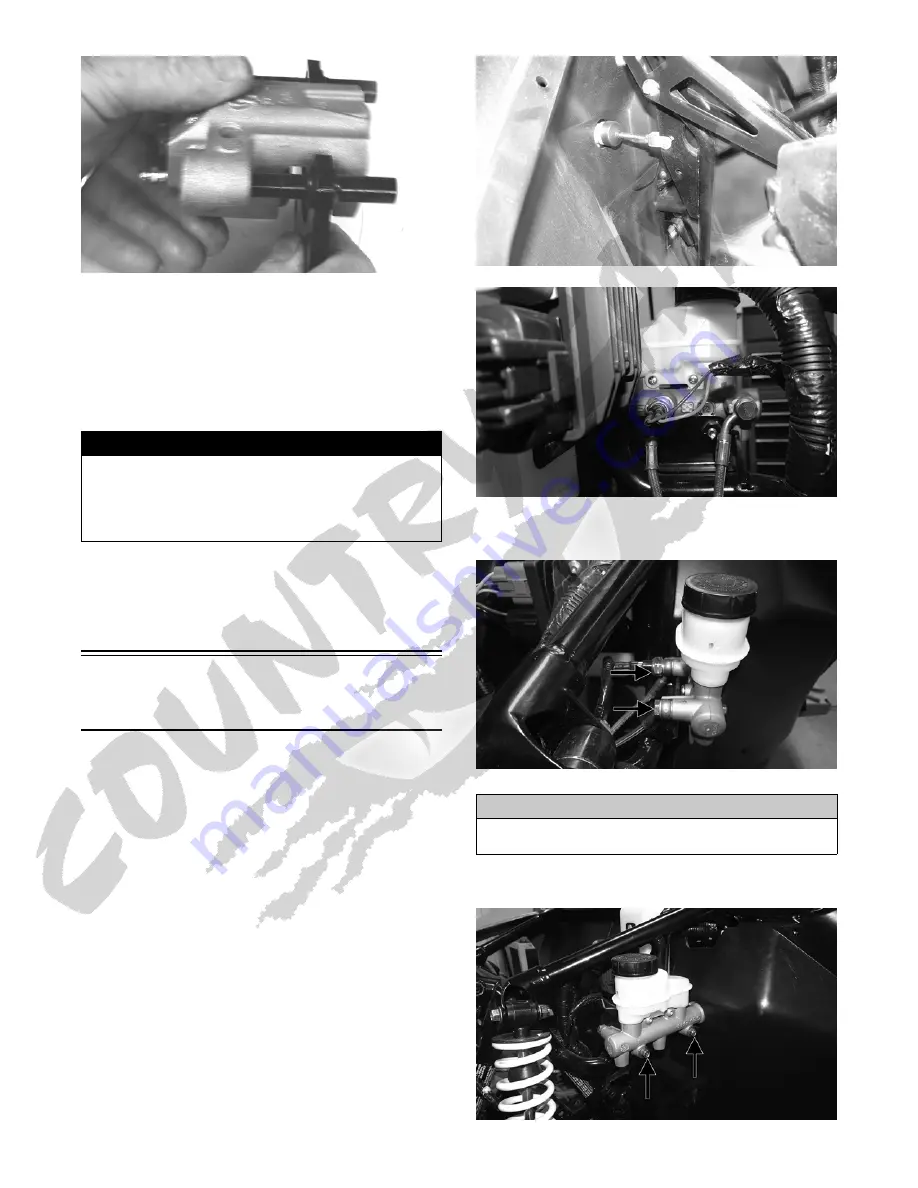
6. Place the brake caliper assembly into position and
secure with new “patch-lock” cap screws. Tighten the
caliper to 20 ft-lb.
7. Place a new crush washer on each side of the brake hose
fitting and install it on the caliper. Tighten to 20 ft-lb.
8. Fill the reservoir; then bleed the brake system (see
Periodic Maintenance/Tune-Up).
9. Install the wheel; then using a crisscross pattern,
tighten the wheel nuts in 20 ft-lb increments to a final
torque factor of 80 ft-lb.
10. Remove the vehicle from the support stand and verify
brake operation.
Master Cylinder
Assembly
NOTE: The master cylinder is a non-serviceable
component; it must be replaced as an assembly.
REMOVING
1. Slide a piece of flexible tubing over the front left
brake caliper bleeder valve and direct the other end
into a container. Remove the master cylinder cover;
then open the bleeder valve. Allow the brake fluid to
drain until the reservoir is empty.
2. Remove the cotter pin and pivot pin from the yoke; then
disconnect the two spade connectors from the switch.
WT514A
WT512
3. Remove the two banjo bolts securing the banjo fittings
to the master cylinder. Discard the four crush washers.
WT511A
4. Remove the two cap screws securing the master cylin-
der to the frame.
WT513A
! WARNING
Never use brake fluid from an open container or reuse
brake fluid. Moisture-contaminated brake fluid could cause
vapor build-up (expansion) during hard braking resulting in
greatly increased stopping distance or loss of control lead-
ing to injury or death.
CAUTION
Brake fluid is highly corrosive. Do not spill brake fluid
on any surface of the vehicle.


