background image

Service Support Spirit                 


Unique Solution                                    

  WWW.ARCBRO.COM


79 

8.7.8 Clear File 

In the main interface, press 

F5 Diagnose

,then press 

F8 System definition

,then 

press 

F7 Clear File

, the system will clear all G code file of system. 

8.7.9 System Update 

In the main interface, press 

F5 Diagnose

,then press 

F8 System definition

,then 

press 

F8 System update

, after press 

Enter

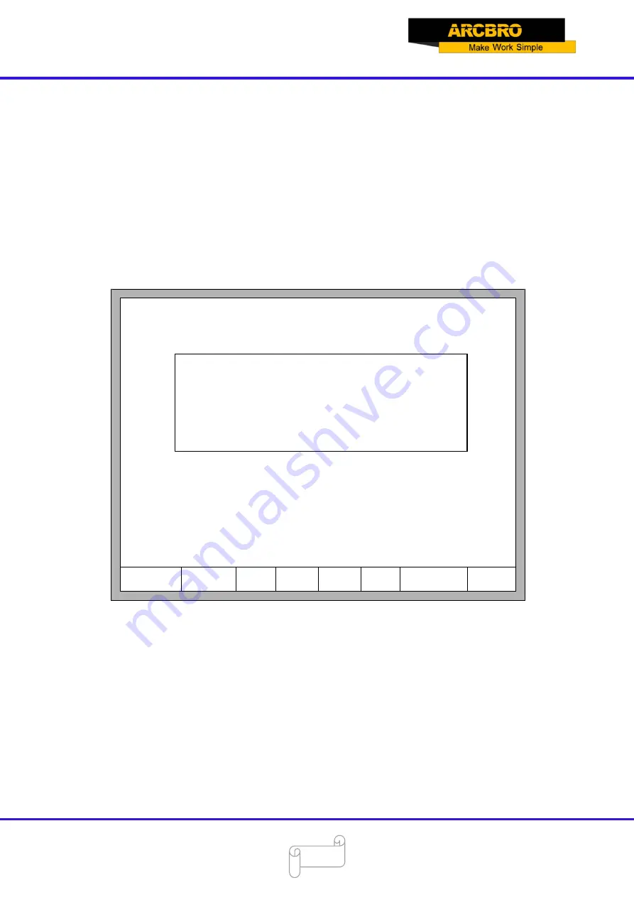
and confirm, it will prompt to update as the 

figure 8.13 shows. 

F1ParaRecover

F8Update

F2ParaBackup

F4Encrypt

F3Define

F6Lan

F7clear File

F5UnEncry

F1: Function Update
F2: Welcome Update
F3: Motion Update
F4: System recovery


Fig 8.13 The prompt of system update 

Function Update: after press 

F1

, it will update function. The function update file is 

F2100B.exe or UserApp.exe. 

Welcome Update: after press 

F2

, it will update the welcome interface. This welcome 

interface is the first shown interface after power on. If you want to find the method of make new 
welcome interface, please contact with our after-sale service department. 

Motion Update: after press 

F3

, it will update the motion. The motion update file is 

MOTION.dsp. 

Summary of Contents for F2000 Tube Series

Page 1: ...Service Support Spirit Unique Solution WWW ARCBRO COM 1 ARCBRO F2000 Tube series CNC SYSTEM User s Manual Operator Manual ARCBRO Revision 2 English Date of issue August 2019...

Page 2: ...3 5 2 Typical Code 13 2 CNC System Instruction 14 2 1 Introduction of System Operation Board 14 2 2 Power on Processing and Main Interface 15 2 3 Function Index of Main Interface 17 Chapter 3 Cutting...

Page 3: ...File 52 6 6 Compile Code 52 6 7 Folder Manager 52 6 8 Clear File 54 Chapter 7 Parameter Setting 55 7 1 Common Parameters 56 7 2 Flame Parameters 57 7 3 Plasma Parameters 58 7 4 Powder Parameters 60 7...

Page 4: ...n 84 10 1 Code Symbol and Interpretation 84 10 2 Coordinate System 85 10 3 G Code Explanation 86 10 4 M Code Explanation 93 Chapter 11 Use of BIOS 95 11 1 System Upgrade 96 11 2 Welcome Interface Upgr...

Page 5: ...work for you since the day you receive machine When you have any questions during assembling or operating it is free to contact us by Call Email Online help 7x24 hours Wish you enjoy a wonderful CNC...

Page 6: ...Module Function Supporting 2 axes cutting tube machine with chuck mode Supporting 2 axes cutting tube machine with friction disk mode Supporting tube and plate all in one chuck mode cutting machine S...

Page 7: ...0000 0 s TorchDn 0000 0 s Follow up 0000 0 s Manual F StepMov StepDis G 5 00 Flame Cu M CutSpeed X 1000 000 Kerf 1 200 ManualSpd Y 3000 000 Angle 00 00 Fig 2 1 Tube plate cutting main Interface After...

Page 8: ...Follow up 0000 0 s Manual F StepMov StepDis G 5 00 Flame Cu M CutSpeed X 1000 000 Kerf 1 200 ManualSpd Y 3000 000 Angle 00 00 Fig 2 2 Cutting plate interface 2 2 Tube Plate Cutting Switch F1 Common F...

Page 9: ...ck Pulse Number F1 Common F2 YAG Laser F3 Plasma F5 System F6 Import F7 Export F8 Save Horizontal Axis Pulses 125 000 n mm Vertical Axis Pulses 125 000 n mm Max cutting speed 2000 000 mmpm Max G00 spe...

Page 10: ...troller Type No Default Coordinate Absolute Coordinate Arc IJ Coordinate Relative Coordinate Default unit Metric Fitting short line No Use chuck Yes Press to change Restart after change default unit F...

Page 11: ...ystem controller topology Schematic As the above figure shows the signal of X Axis is used for controlling cart s motor the signal of Y Axis is used for controlling chuck s or trolley s motor At the s...

Page 12: ...t Reserved output Laser brake Torch up Torch down Blow Follow up Plasma location Plasma arc starting Corner low speed Powder Tube cutting mode Dust preheat F3 OpenOut F4 CloseOut Fig 4 1 Output diagno...

Page 13: ...D 168 It interprets that the tube s diameter is 168 mm in this cutting program Wall Thickness Code There is one line code in the cutting tube code as following omissible T 8 It interprets that the tu...

Page 14: ...interface or Torch down in other interface F HOME Accelerate or skip to the head of code line F END Decelerate or skip to the tail of code line 1 9 During the cutting process change the cutting speed...

Page 15: ...7 F1 ShapeLib F2 Files F3 PartOption F4 Setups F5 Diagnose F6 ZoomIn F7 ManualMove F8 Zero FLSK F2200B Version 3 3 73 1 Speed 00000 File SHAPE_43 TXT Status Stop Current Line Hole 00000 00000 X 500 0...

Page 16: ...iagnosis system self check date setting and system self defines F6 ZoomIn Zoom in the shape in full screen F7 ManualMove Manually move the machine F8 Zero Clear the coordinate of X and Y before starti...

Page 17: ...Revert F8 OK F1 common F2 Flame F3 Plasma F5 System F6 Import Parameters F7 Export Parameters F8 Save F1 Input Diagnose F2 Output Diagnose F5 Keyboard Diagnose F6 System Self check F7 Date time F8 Sy...

Page 18: ...ualSpd Y 3000 00 Angle 0 00 3 1 2 Fig 3 1 cutting function interface Shows the current workpiece s cutting path including the slotted value Shows the G code being processed shows the current and next...

Page 19: ...peed each decrease of 1 click rate Decrease the rate of manual moving machine in manual mode F5 Increase the cutting speed each 1 increase in click rate Increase the rate of manual moving machine in m...

Page 20: ...Unique Solution WWW ARCBRO COM 20 3 1 Cutting Operation Index Cutting Interface F1 Back F2 Demo F3 GoBack Frame F4 Speeddown F8 Jump to pierce ZoomIn F5 Speedup F6 Preheat down F7 Preheat up Fig 3 2 C...

Page 21: ...n the operation panel press the number keys 1 9 the speed will quickly adjust to the corresponding percentage figures 10 times for example press 3 adjust to 30 of the speed limit you have set press 8...

Page 22: ...ent program if the current row is not G01 G02 or G03 the system will directly continue the current line program 3 5 Edge Cutting Offset Cutting Return When the torch is not on the actual path of the c...

Page 23: ...e the preheat time and increase cutting efficiency This function is the commonly used edge perforation function If press X the system considers current point is the paused point it will continue cutti...

Page 24: ...0 X 0 00 Y 500 00 Y 0 00 1 TEST PATTERN 2 G92 X 000000 0 Y 000000 0 Manual F keepMov StepDis G 5 00 Flame Cu M CutSpeed X 1000 00 Kerf N 1 20 ManualSpeed Y 3000 00 Angle 0 00 Are you sure to return EN...

Page 25: ...rn operation after pressing of F3 Number of back to reference and stop has no limit 3 7 Oxygen Gas Preheat Time Regulation In the preheat process press the START F9 key to skip the process of preheat...

Page 26: ...nterface the countdown increases by 15 seconds and the next time you need to preheat the initial preheat time be 75 seconds 3 8 Perforation Point Selection Before you start cutting or cutting is pause...

Page 27: ...5 00 Flame Cu M CutSpeed X 1000 00 Kerf N 1 20 ManualSpeed Y 3000 00 Angle 0 00 X Xmirror Y Ymirror Input No of pierces Press select No of pierce 0 F8 OK Fig 3 7 pierce prompt Pierce point can be inpu...

Page 28: ...ing Esc the system will not exit get into the automatically interface and go on with the cutting operation at the current place FLSK F2200B Version 3 3 71 1 Speed 00000 File SHAPE_43 TXT Status Stop C...

Page 29: ...at s HighPreheat s Pierce1 s Pierce2 s Pierce3 s TorchUp s TorchDn s THC En Blow s Fig 3 10 Walk along frame Before the beginning of the process if press Space the system will enter into the interface...

Page 30: ...7 Revert FLSK F2200B Version 3 3 71 1 Speed 00000 File SHAPE_43 TXT Status Stop Current Line Hole 00000 00000 Operate Mode PartOption X 000000 0 Y 000000 0 Manual F keepMov StepDis G 5 00 Flame Cu M C...

Page 31: ...to relevant location For example press F4 part s start point will automatically jump to lower right corner As the following figures show X 000000 0 Y 000000 0 X Xmirror Y Ymirror FLSK F2200B Version...

Page 32: ...SK F2200B Version 3 3 71 1 Speed 00000 File SHAPE_43 TXT Status Stop Current Line Hole 00000 00000 F1 StartPoint F2 Angle F3 Array F4 Scale F5 SelLinePierce F6 EditFile F7 Revert F8 OK Fig 4 3 After p...

Page 33: ...e SHAPE_43 TXT Status Stop Current Line Hole 00000 00000 Operate Mode PartOption X 000000 0 Y 000000 0 X Xmirror Y Ymirror F8 OK F1 StartPoint F2 Angle F3 Array F4 Scale F5 SelLinePierce F6 EditFile F...

Page 34: ...Manual F keepMov StepDis G 5 00 Flame Cu M F1 StartPoint F8 OK Enter Return back ESC Don t move back Angle 10 048 Fig 4 6 Return to the start point after adjusting 4 3 2 Steel Plate Adjust Angle Memo...

Page 35: ...ere needs to be as the angle of steel plate adjusting please refer to section 8 7 6 8 4 4 Array In the part options menu press F3 the system will prompt as Fig 4 7 there are three ways to arrange arra...

Page 36: ...gle F8 OK CutSpeed X 1000 00 Kerf N 1 20 ManualSpeed Y 3000 00 Angle 0 00 Manual F keepMov StepDis G 5 00 Flame Cu M Fig 4 8 Arrange in matrix The result is shown in fig 4 9 BFLSK F2200B Version 3 3 7...

Page 37: ...irror F8 OK F1 StartPoint CutSpeed X 1000 00 Kerf N 1 20 ManualSpeed Y 3000 00 Angle 0 00 Manual F keepMov StepDis G 5 00 Flame Cu M Fig 4 10 Staggered arrange The result is shown in figure 4 11 F4 Sc...

Page 38: ...G 5 00 Flame Cu M Enter parameter unit mm rows 2 Cols 2 RowSpc 500 00 ColSpc 500 00 RowNest 500 00 ColNest 500 00 F8 OK F1 StartPoint F2 Angle F8 OK Fig 4 12 Arrange in Nest The result is shown in fi...

Page 39: ...500 00 Y 0 00 Operate Mode PartOption X 000000 0 Y 000000 0 Enter proportion 1 00 X Xmirror Y Ymirror CutSpeed X 1000 00 Kerf N 1 20 ManualSpeed Y 3000 00 Angle 0 00 Manual F keepMov StepDis G 5 00 Fl...

Page 40: ...00 Manual F keepMov StepDis G 5 00 Flame Cu M Fig 4 15 Select Line Pierce 4 6 1 Select Row Press F1 to select the number of row to start cutting with the system prompts F5 SelLinePierce F6 EditFile F...

Page 41: ...Mov StepDis G 5 00 Flame Cu M Fig 4 17 Select row After selecting row press F8 to confirm 4 6 2 Select Number The operation is similar to the choosing row operation 4 6 3 Operation after Select Row Nu...

Page 42: ...ce1 s Pierce2 s Pierce3 s TorchUp s TorchDn s THC En Blow s CutSpeed X 1000 00 Kerf N 1 20 ManualSpeed Y 3000 00 Angle 0 00 Manual F keepMov StepDis G 5 00 Flame Cu M Fig 4 19 Operation after selectin...

Page 43: ...Pierce2 s Pierce3 s TorchUp s TorchDn s THC En Blow s CutSpeed X 1000 00 Kerf N 1 20 ManualSpeed Y 3000 00 Angle 0 00 Manual F ContiMov StepDis G 5 00 Flame Cu M Fig 5 1 Manual function interface The...

Page 44: ...y is pressed and then released and when the directory key or stop key is pressed the system will stop 5 3 Fixed length Moving Function In the manual interface press F3 to enter the interface of fixed...

Page 45: ...as the breakpoint and remember it When you need to process after the breakpoint after the system powers on don t move the torch press F7 in the main interface to enter the manual function interface t...

Page 46: ...Pierce2 s Pierce3 s TorchUp s TorchDn s THC En Blow s CutSpeed X 1000 00 Kerf N 1 20 ManualSpeed Y 3000 00 Angle 0 00 Manual F StepMov StepDis G 5 00 Flame Cu M 7 G01 X500 00 Y0 8 G01 X0 Y 500 00 Fig...

Page 47: ...de to enter local machine code interface shown as follows F1 DiskFile F2 UDisk F3 Search F4 EditFile F5 DelFile F6 CopyToU F7 Preview F8 OK Work folder flash 0 flash 1 DIR1 2 DIR2 3 DIR3 4 DIR4 5 DIR5...

Page 48: ...position of the cursor is txt file or cnc file you could preview the current graphic 1 SHAPELIB SHAPE_18 TXT 2 SHAPELIB SHAPE_00 TXT 3 SHAPELIB SHAPE_01 TXT 4 SHAPELIB SHAPE_43 TXT 5 SHAPELIB SHAPE_ T...

Page 49: ...internal documents Note When you open a file on U disk you must save it as the local machine code before you start cutting When saved the U disk documents file name automatically memory shown as Fig...

Page 50: ...dPart abs 7 SHAPELIB UsedNoKf abs file exist confirm to cover Enter confirm ESC cancel Fig 6 4 Replacement documents If you want to replace the internal documents press Enter key if you want to change...

Page 51: ...sor to the file that you want to edit then press F4 to enter the edit interface When enter the characters some keys are reuse keys Press these keys directly enter the characters under the button If fi...

Page 52: ...an new file to input your own code 6 6 Compile Code After create a new code or edit the code if you want to know the code is valid or not in the edit interface press F1 you can compile code to check w...

Page 53: ...art abs 7 SHAPELIB UsedNoKf abs Work folder flash DIR1 0 flash 1 DIR1 2 DIR2 3 DIR3 4 DIR4 5 DIR5 6 DIR6 7 DIR7 8 DIR8 9 DIR9 Fig 6 6 Folder 1 The current folder will switch into flash DIR1 and then a...

Page 54: ...e edit file show as figure 6 8 F1Compile F2AddRow F3Del Row F4NewFile F5NewFolder F8Save Fig 6 8 Edit file interface At this time press F5 input the folder s name in the prompting frame and then press...

Page 55: ...e 1 000 mm Corner speed 1 100 100 000 mmpm Cutting type Flame Demo Run Speed 1000 000 mmpm F4 Powder Fig7 1 Parameter Interface You can set five kinds of parameter in the parameter interface a Common...

Page 56: ...tion to work piece Before cutting a work piece you can modify kerf gap value once begin to cut you are not permitted to modify the value Corner speed Plate thickness affect the cutting tip s ac dc rat...

Page 57: ...HC enable No Hold preheat Yes Edge cutting enable No F4 Power Fig 7 2 Flame Parameters Ignition Time the time delay of opening ignition I O Low Preheat Time The preheating time before perforating the...

Page 58: ...at the torch needs to lift up when it needs to move to another place after the current cutting is over while the Pierce Up Time means the time that the torch needs to lift up after preheating in the f...

Page 59: ...me to wait At this point all output I O are turned off Enter any positive number unit is s Pierce time Perforation time Enter any positive number unit is s Torch Up Time When arc press is turned off t...

Page 60: ...put the situation is considered to be broken arc This parameter can effectively avoid the arc broken alert because of the sensitivity of the broken arc detection in the cutting methods with lead this...

Page 61: ...Fig 7 4 powder parameters Marker Ignition Time input 0 arbitrary value unit s Marker Preheat Time input 0 arbitrary value unit s Mix powder Open Close Time Delay time of scatter powder mouth relative...

Page 62: ...eed below radius 0 00 mm Flame adjust time 0 40 s Plasma adjust time 0 30 s Emergency stop time 0 08 s Start speed 250 000 mm Max X 100000 000 mm Max Y 100000 000 mm Min X 100000 000 mm Min Y 100000 0...

Page 63: ...o the time when the motor is up to the cutting speed Emergency STOP Time When encounter Emergency Stop input the time for dropped from the current speed to zero Start Speed the system s speed when it...

Page 64: ...xport F8 Save Horizontal Axis Pulse 125 000 n mm Vertical Axis Pulse 125 000 n mm Max cutting speed 2000 000 mmpm Max G00 speed 6000 000 mmpm Max Manual speed 3000 000 mmpm Small arc limit 500 000 mmp...

Page 65: ...m Vertical Axis Pulse 125 000 n mm Max cutting speed 2000 000 mmpm Max G00 speed 6000 000 mmpm Max Manual speed 3000 000 mmpm Small arc limit 500 000 mmpm Limit speed below radius 0 00 mm Flame adjust...

Page 66: ...lame F3 Plasma F5 System F6 Import F7 Export F8 Save F4 Powder Parameter saved successfully Fig 7 8 System Parameters Note when any parameter has been modified you must take preservation operation to...

Page 67: ...e F8SystemDef input forward limit back limit right limit left limit emergency stop arcing feedback Position detect Plasma Collision Move up input Move down input Move left input Move right input Accel...

Page 68: ...pt F5 UnEncry F6 Language F5 Keyboard Diagnosis F7 Date Time F7 ClearFile F8 Update Fig 8 2 Diagnosis interface index 8 2 Input Diagnosis The system will read current IO information when press F1 Refr...

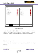
Page 69: ...tect Arc starting HoldTorch Marker Output Mix powder Dust preheat F3 OpenOut F4 CloseOut Fig 8 3 Output diagnosis Press you can move the cursor to the corresponding output port press F3 to open the co...

Page 70: ...ution WWW ARCBRO COM 70 F1 Input F2 Output F5KeyBrd F6SelfCheck F7DateTime F8SystemDef Key Code 005 Fig 8 4 Keyboard Diagnosis 8 5 System Self check In the system diagnosis interface press F6 to enter...

Page 71: ...stemDef 1 backup parameter first all 2 lose breakpoint 3 restart after selfcheck Are you sure Fig 8 5 System self check If the self check is OK the system will show Self check pass Fig 8 6 Self check...

Page 72: ...nterface to set the date and time F1 Input F2 Output F5KeyBrd F6SelfCheck F7DateTime F8SystemDef 2013 05 22 15 51 37 Wen Press up or down to modify Fig 8 7 System time Move the cursor to the correspon...

Page 73: ...efinition F1 Parameter Reset Warning After resetting successfully please restart the system 8 7 2 Input Definition The controller could change the IO definition including changing the order of IO numb...

Page 74: ...stom definition interface press F3 to enter the definition interface press F1 to enter the input definition interface As shown in fig 8 9 F1 Input F2 Output F8 Save definition of output F3 Axes F4 Mot...

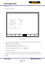
Page 75: ...ansistor is on Type means that is the output signal is effective the transistor is off 8 7 4 Coordinate Definition The system could provide IO definition for the user As shown in Fig 8 10 Fig 8 10 Coo...

Page 76: ...move the cursor to the axes of which needs to change motor rotation direction then press Enter the motor direction can switch between positive and reversal XY exchange if this function is YES output p...

Page 77: ...hange Restart after change default unit Fig 8 12 Option Press left or right key in this interface remote controller s type can be set arbitrarily one of the three types which are NO P2P 8421 NO type n...

Page 78: ...ault condition the angle after steel plate is adjusted has no memory After this parameter is set Yes steel plate angle memory will be automatically stored until the steel plate is adjust again or the...

Page 79: ...r F8Update F2ParaBackup F4Encrypt F3Define F6Lan F7clear File F5UnEncry F1 Function Update F2 Welcome Update F3 Motion Update F4 System recovery Fig 8 13 The prompt of system update Function Update af...

Page 80: ...is time the system is exhaustively recovered back to the status before leaving factory in other words the parameters IO ports configuration coordinate direction definition and so on are all recovered...

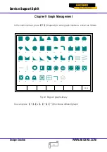
Page 81: ...the main interface press F1 ShapeLib to enter graph interface shown as follows F8 OK 0 1 2 8 3 4 5 10 6 7 9 11 15 16 23 17 18 21 22 24 25 26 27 28 29 30 31 32 33 34 35 36 37 38 39 40 41 42 43 44 12 1...

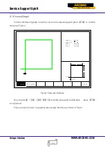
Page 82: ...ired graph press F8 to confirm shown as Fig 9 2 F1 Inside F8 OK 1 2 Lead in Lead In 10 00 Lead Out 10 00 Size 1 100 00 Size 2 100 00 Lead out F2 Outside Fig 9 2 Chip size interface You can press to mo...

Page 83: ...as Fig 9 3 F1 Inside F8 OK 1 2 Lead in Lead In 10 00 Lead Out 10 00 Size 1 100 00 Size 2 100 00 res 1 L C apart Lead out F2 Outside Fig 9 3 Hole size Modify sizes like modify chip sizes After modific...

Page 84: ...ction interpretation N Programming segment number G Code for ready M Auxiliary function X Relative coordinate or absolute coordinate of X axle Y Relative coordinate or absolute coordinate of Y axle U...

Page 85: ...esents parameter value for example Xn expresses that n is the following parameter means optional context which can be selected or not 10 2 Coordinate System This system uses right hand Descartes coord...

Page 86: ...ne cutting G02 Parameter X U Y V I J Clockwise arc cutting G03 Parameter X U Y V I J Anticlockwise arc cutting 1 G92 Reference point setting Format G92 Xn Yn Parameters meaning Xn Yn expresses absolut...

Page 87: ...mat G90 G91 G90 absolute coordinate X Y in the code means absolute coordinate value U and V mean relative coordinate value G91 relative coordinate X Y in the code means relative coordinate value U and...

Page 88: ...int Format G00 X Un Y Vn Fn Parameters meaning Fn rapidly moving to specific location at the limited rate Un displacement of endpoint s X coordinate relative to start point of current segment unit mm...

Page 89: ...expresses linearly walking meaning output ports are all closed but G01 expresses linearly incising 6 G02 Clockwise Circular Interpolation This instruction expresses that incise clockwise arc clockwis...

Page 90: ...n displacement of endpoint s X coordinate relative to working start point unit mm Yn displacement of endpoint s Y coordinate relative to working start point unit mm Example Example 1 B A G92 X0 Y0 Ref...

Page 91: ...G41 Enable Left Kerf Compensation incision code G40 Disable Left Kerf Compensation G42 Enable Right Kerf Compensation incision code G40 Disable Right Kerf Compensation Example Convex Roof Trapezoid w...

Page 92: ...so cannot If there is G99 the parameter X Y I J after code should not be ignored Mirror image and rotation will take the origin 0 0 of Descartes coordinate as reference point 10 Programme notice items...

Page 93: ...No parameter Cutting device off M00 No parameter End of instruction M02 No parameter End of program M07 Cutting device on Ignition Torch Preheat oxygen Incision oxyen Acetylene 1 2 3 4 5 6 7 Fig 10 6...

Page 94: ...ation up time 6 Close torch up open incision oxygen open perforation down and delay Perforation down time 7 Close torch down begin to incise M08 Cutting device off 1 Close incision oxygen 2 Open torch...

Page 95: ...to run BIOS Auto boot after 3 Fig 11 1 Power on When press DEL before the system counts down to 0 the system will enter the BIOS If other keys are pressed the system will enter in before counting dow...

Page 96: ...re should be the upgrade file WELCOME bmp in the root folder of the flash disk Press F2 to upgrade when the conditions are satisfied when completing the upgrading press F6 to reboot 11 3 Movement Cont...

Page 97: ...Service Support Spirit Unique Solution WWW ARCBRO COM 97...

Reviews: