


UG-1262
Rev. B | Page 292 of 312
Bits Bit
Name
Settings
Description
Reset
Access
4 MOD60ALMEN
Enable WUT Modulo 60 Counting of Time Past a Modulo 60 Boundary. Enables the
detection of the counter passing a value of 60, whereas MOD60ALMINTEN
enables the generation of a resultant interrupt.
0x0 R/W
0
Disable determination of Modulo 60 WUT elapsed time.
1
Enable determination of Modulo 60 WUT elapsed time.
3
Reserved
Reserved. Clear to 0.
0x0
R/W
2 ALMINTEN
Enable ALMINT Sourced Alarm Interrupts to the CPU. ALMINTEN gives the CPU
extra control over whether an alarm event (alarm count matches the WUT count)
triggers an interrupt. Under normal conditions, ALMINTEN is set active, most
notably when the detection of an alarm condition is enabled by ALMEN. If alarm
interrupts enabled but the alarm itself is disabled, no interrupts occur.
0x1 R/W
0
Disable alarm interrupts.
1
Enable an interrupt if the WUT alarm and count values match.
1 ALMEN
Enable the WUT Alarm Absolute Operation. This bit must be set active for the
alarm logic to function and for any alarm event to be detected. Such an event
is defined as a match between the values of the WUT count and alarm registers,
namely CNT1, CNT0, CNT2, ALM1, ALM0, and ALM2. Count and alarm values
and match conditions are defined on a 47-bit basis, although the constituent
registers are individually 16 bits wide. When enabled by ALMEN, the detection of
an alarm event is held in the sticky interrupt source bit field, ALMINT, of the
status register, SR0.
0x0 R/W
0
Disable detection of alarm events.
1
Enable detection of alarm events.
0 CNTEN
Global Enable for the WUT. CNTEN enables counting of elapsed real time and
acts as a master enable for the WUT. If the WUT is enabled by activating CNTEN,
this event causes a realignment of the prescaler and the Modulo 60 counter
used by the WUT to generate MOD60ALMINT sourced interrupts in SR0.
0x0 R/W
0
Disable the WUT.
1
Enable the WUT.
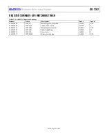
STATUS 0 REGISTER
Address: 0x40001404, Reset: 0x7F88, Name: SR0
Information on WUT operation is made available to the CPU via three status registers: SR0, SR1, and SR2. These registers include all
flags related to CPU interrupt sources and error conditions within the WUT.
Table 381. Bit Descriptions for SR0
Bits Bit
Name
Settings Description
Reset Access
15 Reserved
Reserved.
0x0 R
14 ISOENB
Visibility Status of 32 kHz Sourced Registers, Taking Account of Power Domain
Isolation. This bit indicates whether 32 kHz sourced MMRs in the always on half of
the WUT are visible to the CPU. During normal powered operation, ISOENB is high,
confirming that all registers are visible. If ISOENB is low when the device is emerging
from hibernation, 32 kHz sourced information is not yet available to the CPU.
0x1 R
0
32 kHz sourced MMRs in the always on half of the WUT are not yet visible to the
CPU due to isolation.
1
32 kHz sourced MMRs in the always on half of the WUT are visible to the CPU.
13 Reserved
Reserved.
0x1 R
12 WSYNCALM1
Synchronization Status of Posted Writes to the ALM1 Register. WSYNCALM1
indicates if the effects of a posted write to ALM1 are visible to the CPU.
0x1 R
0
Results of a posted write are not yet visible to the CPU.
1
Results of a posted write are visible to the CPU.


