


UG-1262
Rev. B | Page 291 of 312
REGISTER DETAILS: DIGITAL DIE WAKE-UP TIMER
CONTROL 0 REGISTER
Address: 0x40001400, Reset: 0x03C4, Name: CR0
CR0 is the primary of two control registers for the WUT, the other being CR1. All mainstream WUT operations are enabled and disabled
by the CPU using CR0. The granularity of the WUT control is expanded by the CR1 register.
Table 380. Bit Descriptions for CR0
Bits Bit
Name
Settings
Description
Reset
Access
15 WPNDINTEN
Enable WPENDINT Sourced Interrupts to the CPU. This field is an enable for WUT
interrupts to the CPU, based on the WPENDINT sticky interrupt in the SR0 register.
0x0 R/W
0
Disable WPENDINT sourced interrupts to the CPU.
1
Enable WPENDINT sourced interrupts to the CPU.
14 WSYNCINTEN
Enable WSYNCINT Sourced Interrupts to the CPU. WSYNCINTEN is an enable for
WUT interrupts to the CPU based on the WSYNCINT sticky interrupt source field of
the SR0 MMR. WSYNCINTEN is activated whenever the effects of a posted
write to a 32 kHz sourced MMR or MMR bit field become visible to the CPU.
0x0 R/W
0
Disable WSYNCINT sourced interrupts to the CPU.
1
Enable WSYNCINT sourced interrupts to the CPU.
13 WPNDERRINTEN
Enable WPNDERRINT Sourced Interrupts to the CPU when a WUT Register
Write Pending Error Occurs. Write pending errors can be avoided by the CPU
by checking the pending status of a register in SR1 before undertaking a write
to that register. If a WPNDERRINT error occurs, and this bit is set to 1, the WUT
interrupts the CPU.
0x0 R/W
0
Disable interrupts if write pending errors occur in the WUT.
1
Enable interrupts for write pending errors in the WUT.
12 ISOINTEN
Enable ISOINT Sourced Interrupts to the CPU. This bit enables interrupts to the
CPU based on the ISOINT sticky interrupt source in the SR0 status register.
When power loss is imminent to all power domains on the device apart from
the WUT, the WUT activates its isolation barrier so that the WUT can continue
to operate independently of the core. When power is subsequently restored to
the rest of the device, the WUT activates the ISOINT interrupt source to act as a
sticky record of the power loss event just finishing. This activation occurs as the
WUT lowers its isolation barrier when the core regains power. If enabled by
this bit, the WUT interrupts the CPU based on ISOINT. The CPU can then inspect
the ISOINT field of SR0 to determine if the CPU has recovered from a total loss
of power.
0x0 R/W
0
Disable ISOINT sourced interrupts to the CPU.
1
Enable ISOINT sourced interrupts to the CPU.
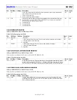
11 MOD60ALMINTEN
Enable Periodic MOD60ALMINT Sourced Interrupts to the CPU. This bit allows the
CPU to enable a periodic, repeating interrupt from the timer at a displacement
time in WUT time units given by the MOD60ALM bit beyond a Modulo 60
boundary.
0x0 R/W
0
Disable periodic interrupts due to Modulo 60 WUT elapsed time.
1
Enable periodic interrupts due to Modulo 60 WUT elapsed time.
[10:5] MOD60ALM
Periodic Modulo 60 Alarm Time in Prescaled WUT Time Units Beyond a
Modulo 60 Boundary. This bit allows the CPU to position a periodic alarm
interrupt from the WUT at any integer number of prescaled WUT time units
from a Modulo 60 boundary (roll over event) of the value in CNT1 and CNT0.
Values of 0 to 59 are allowed for MOD60ALM. If a greater value is configured,
this value is treated as zero prescaled WUT time units. Boundaries are defined
when the CPU writes a new pair of values to the CNT1 and CNT0 registers, the
CPU enables the WUT from a disabled state using CR0, Bit 0, or when the WUT
is enabled by CR0, Bit 0. For example, a value of 30 results in the Modulo
60 periodic interrupt from the WUT to be issued to the CPU at 30 time units
past a Modulo 60 boundary.
0x1E R/W


