


UG-1262
Rev. B | Page 95 of 312
Bits Bit
Name Settings
Description
Reset
Access
9
SW9
SW9 Switch Control Active High.
0x0
R/W
0
Open
switch.
1
Close
switch.
8
SW8
SW8 Switch Control Active High.
0x0
R/W
0
Open
switch.
1
Close
switch.
7
SW7
SW7 Switch Control Active High.
0x0
R/W
0
Open
switch.
1
Close
switch.
6
SW6
SW6 Switch Control Active High.
0x0
R/W
0
Open
switch.
1
Close
switch.
5 SW5
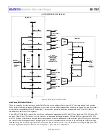
SW5 Switch Control Active High. Close to connect external capacitor or R
TIA
between the RC0_0 and RC0_1 pins.
0x0 R/W
0
Open
switch.
1
Close
switch.
4
SW4
SW4 Switch Control Active High.
0x0
R/W
0
Open
switch.
1
Close
switch.
3
SW3
SW3 Switch Control Active High.
0x0
R/W
0
Open
switch.
1
Close
switch.
2
SW2
SW2 Switch Control Active High.
0x0
R/W
0
Open
switch.
1
Close
switch.
1
SW1
SW1 Switch Control Active High.
0x0
R/W
0
Open
switch.
1
Close
switch.
0
SW0
SW0 Switch Control Active High.
0x0
R/W
0
Open
switch.
1
Close
switch.
LOW POWER TIA CONTROL BITS CHANNEL 1 REGISTER
Address: 0x400C20E8, Reset: 0x00000003, Name: LPTIACON1
Table 111. Bit Descriptions for LPTIACON1
Bits
Bit
Name Settings Description
Reset Access
[31:16] Reserved
Reserved.
0x0 R
[15:13]
TIARFILT
Set Low-Pass Filter Resistor.
0x0
R/W
0
Disconnect TIA output from AIN7_LPF1 pin. Useful for diagnostics where fast
response is required from ADC. Disconnects the low power TIA output from the low-
pass filter capacitor.
1
Bypass
resistor.
10
20
kΩ.
11
100
kΩ.
100
200
kΩ.
101
400
kΩ.
110
600
kΩ.
111
1 MΩ. Recommended value for best dc current measurement performance. Lowest
cut off frequency setting for low-pass filter.


